

Isuzu 6BB1 Diesel Engine Service & Repair Manual
What's Included?
Fast Download Speeds
Online & Offline Access
Access PDF Contents & Bookmarks
Full Search Facility
Print one or all pages of your manual
FOREWORD
The Model 6BBI desel engine, mounted on the Isuzu Model SBR Truck, has been designed
and manufactured based on the outstanding technique and rich experience cultivated during
long years. This high performance engine features its high durability and economy.
To allow the engine displaying its high performance and to maintain optimum condition, a
full knowledge of correct repair method and technique is very important.
This manual covers the construction, and repair and adjustment methods for the overall
6BBI diesel engine. Many photographs and figures shown in the individual section will assist
readers in understanding the engine. Please read this manual carefully and take full advantage of
the information given.
Note that values and other data shown in manual may be changed due to the future design
change or modification.
)
TABLE OF CONTENT
Outline of model 6BBI diesel engine
Model 6BBI diesel engine in sec tio nal view
Main engine data and specifications
T orqu e specification table
SECTION 1. ENGINE
2. LUBRICATING SYSTEM AND
COOLI NG SYSTEM
3. ENGINE AUXILIARIES
4. FUEL SYSTEM
5. ENGINE ELECTRICALS
SUPPLEMENT ENGINE TROUBLE-SHOOTING
AND CORRECTION
Outline of Model GBBI
Diesel Engine
The model 6BB1 is a direct-injection type diesel engine incorporating efficient combustion
chambers (patent applied) which have recently been developed by the Isuzu engineers. The
model 6BB1 diesel engine develops a maximum output of 145 PS and features an excellent
operating economy, dependability, low operating noise and exhaust gas control systems of
advanced design.
Engineering features of the model 6BB1 diesel engine include the following:
1. Designed and built compact yet powerful-piston displacement is 5.393 Itrs with the bore
and stroke of 102mm and 110mm, respectively.
2. Advanced direct-injection method, Isuzu's exclusively designed combustion chambers,
efficient intake parts and direct-injection system ensure a high engine performance.
3. Adopts Isuzu's exclusively designed square-type troidal swirl combustion chambers (patent
applied).
4. Utilizes an efficient RAD injection pump governor and overflow valve is installed on the
fuel pump side.
5. Cylinder head, cylinder liner and piston cooling method has been improved to gain
durability of engine components.
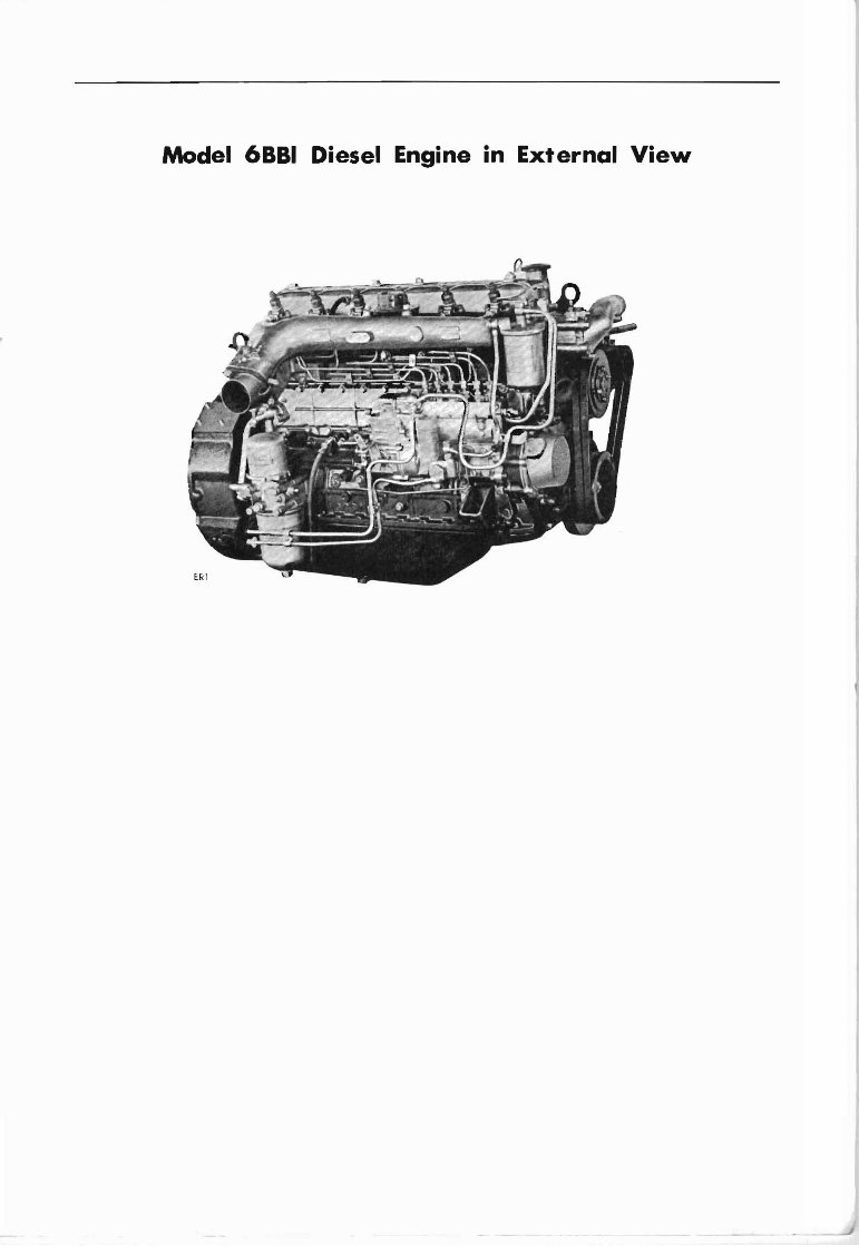
Model 6BBI Diesel Engine in External View
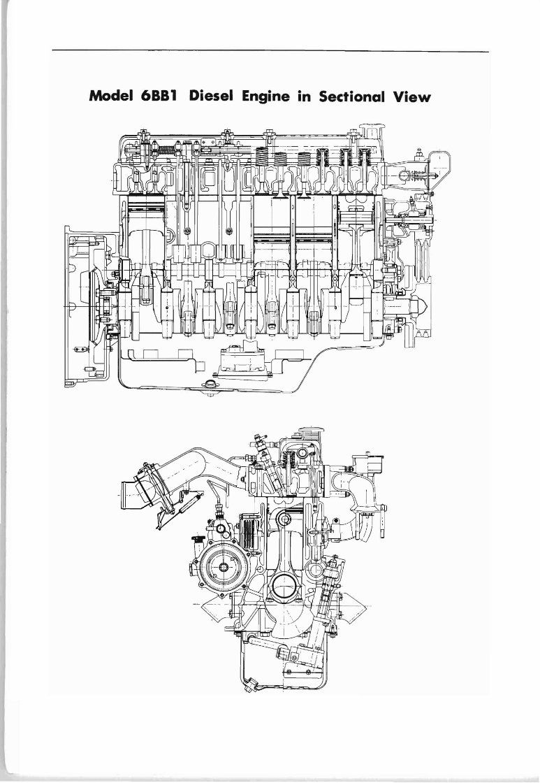
Model 6BB1 Diesel Engine in Sectional View
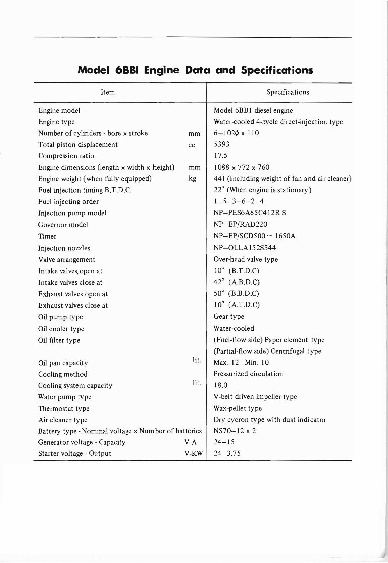
Model 6BBI Engine Data and Specifications
Item Specifications
Pressurized circulation
18 00
V-belt driven impeller type
Wax-pellet type
Dry cycron type with dust indi cator
NS70 -12 x2
24-15
24 -3.75
lit.
lit.
Model 6BB I diesel engine
Water-cooled -l-cycle direct-injection type
mm 6-102¢ x 110
cc 5393
17.5
mm 1088x772x760
kg 441 (In cluding weight of fan and air cleaner)
22° (When engine is stationary)
1-5-3 -6 -2--4
NP-PES6A85C412R S
NP-EP/RAD220
NP-EP /SCD500 - 1650A
NP-OLLA 152S344
Over-head valve type
10° (B.T.D.C)
42° (A.B.D.C)
50° (BoB.DoC)
10° (A.T .D.C)
Gear type
Water-cooled
(Fuel-flow side) Paper element type
(Partial-flow side) Cen trifugal type
Max.TZ Min. 10
Engine model
Engine type
Number of cylinders - bore x stroke
Total piston displacement
Compression ratio
Engine dimensions (length x.width x height )
Engine weight (when fully equipped)
Fuel injection timing B.T.D.C.
Fuel injecting order
Injection pump model
Governor model
Timer
Injection nozzles
Valve arrangement
Intake valves,open at
Intake valves close at
Exhaust valves open at
Exhaust valves close at
Oil pump type
Oil cooler type
Oil filter type
Oil pan capacity
Cooling method
Cooling system capacity
Water pump type
Thermostat type
Air cleaner type
Battery type -Nominal voltage x Number of batteries
Generator voltage - Capacity V-A
Starter voltage - Output V-KW
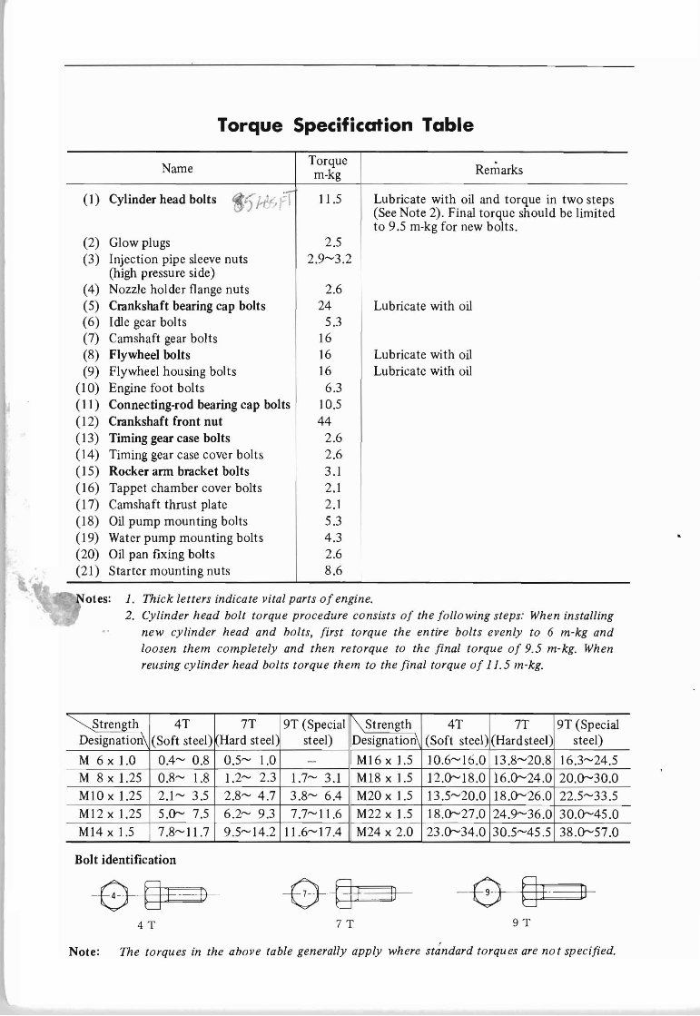
Torque Specification Table
Name
Torque
m-kg
(I) Cylinder head bolts
,. . -,-
11.5
.t) /-t , c" fl
(2) Glow plugs 2.5
(3) Injection pipe sleeve nuts 2.9-3.2
(high pressure side)
(4) Nozzle holder flange nuts 2.6
(5) Crankshaft bearing cap bolts 24
(6) Idle gear bolts 5.3
(7) Camshaft gear bolts 16
(8) Flywheel bolts 16
(9) Flywheel housing bolts 16
(10) Engine foot bolts 6.3
(II) Connecting-rod bearing cap bolts 10.5
(12) Crankshaft front nut 44
(13) Timing gear case bolts 2.6
(14) Timing gear case cover bolts 2.6
(15) Rocker arm bracket bolts 3.1
(16) Tappet chamber cover bolts 2.1
(17) Camshaft thrust plate 2.1
(18) Oil pump mounting bolts 5.3
(19) Water pump mounting bolts 4.3
(20) Oil pan fixing bolts 2.6
(21) Starter mounting nuts 8.6
Remarks
Lubricate with oil and torque in two steps
(See Note 2). Final torque should be limited
to 9.5 m-kg for new bolts.
Lubricate with oil
Lubricate with oil
Lubricate with oil
1. Thick lett ers indicate vital parts of engine .
2. Cylinder head bolt torque procedure consists of the following steps: When installing
new cylinder head and bolts, first torque the entire bolts evenly to 6 m-kg and
loosen them completely and then retorque to the final torque of 9.5 m-kg, When
reusing cylinder head bolts torque them to the final torque of 11.5 m-kg.
~Strength 4T 7T 19T (Special \ Strength 4T 7T 9T (Special
Designation\ (Soft steel) Hard steel), steel) Designation\ (Soft steel) (Hard steel) steel)
M 6 x 1.0 0.4- 0.8 0.5- 1.0 - MI6 x I.5 10.6-16.0 13.8-20.8 16.3-24.5
M 8 x 1.25 0.8- 1.8 1.2- 2.3 1.7- 3.1 MI8 x 1.5 12.0-18.0 i6.0-24 .0 20.0-30 .0
MIO x 1.25 2.1- 3.5 2.8- 4.7 3.8- 6.4 M20 x 1.5 13.5-20.0 18.0-26 .0 22.5-33.5
MI2x 1.25 5.0- 7.5 6 .2- 9.3 7.7-11.6 M22x1.5 18.0-27.0 24.9-36.0 30.0-45.0
M14 x 1.5 7.8-11.7 9.5-14 .2 11.6-17.4 M24 x 2.0 23.0-34 .0 30.5-45.5 38 .0-57.0
Bolt identification
- B--§+ - --- b-
4T 7T 9T
Note: The torques in the above table generally apply where stdndard torques are no t specified.
SECTION 1
ENGINE
CONTENTS
ENGINE REMOVAL 1- 1
ENGINE INSTALLATION 1- 3
1. MAJOR DISASSEMBLy 1- 3
2. SERVICING OF ENGINE COMPONENTS 1- 9
2-1 Cylinder Body : 1- 9
2-2 Crankshaft 1-13
2-3 Pistons and Connecting-Rods 1-18
2-4 Cylinder Head 1-23
2-5 Rocker Arm Shaft and Relative Parts : 1-30
2-6 Camshaft 1-33
2-7 Timing Gears 1-35
3. MAJOR REASSEMBLY 1 -36
4. ADJUSTMENT OF ENGINE CONTROLS 1-44
ENGINE 1-1
Engine Removal
I TOOLS REQUIRED:
I
A set of general tools, wire, hoist (chain
block)
(1) Apply the parking brake firmly and
place the transmission in neutral.
(2) Unlock the cab mounting lock lever on
the right side of the cab. Then, unlock
the cab mounting lock lever on the left
side of the cab.
Release the safety hook lever, while
exerting a pressure onto the cab to
prevent the cab from raising abruptly.
When the cab is raised to a stop
support it in position with the cab
stay .
(3) Disconnect the battery negative (-)
cable.
(4) Drain the cooling system through the
drain cock on the radiator and on the
cylinder block then drain engine oil
completely.
(5) Disconnect the cable connecting the
starter to the battery. Disconnect the
grounding cable to chassis frame.
(6) Disconnect the generator cable at the
connector then disconnect generator
grounding cable.
Fig. 1-1
(7) Disconnect the thermometer unit cord,
oil filter switch cord and glow plug
wiring.
(8) Loosen the clips and remove the
vacuum hose .
(9) Disconnect the exhaust pipe from the
exhaust manifold.
(10) Disconnect the air cleaner rubber hoses
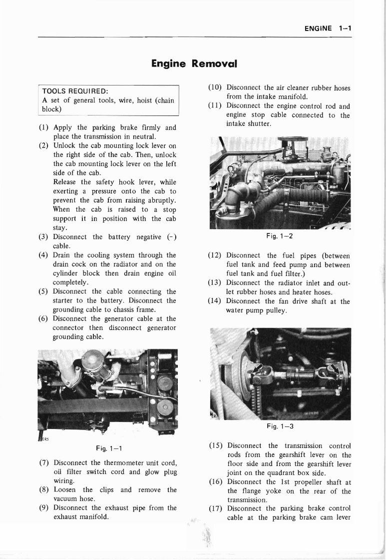
from the intake manifold.
(11) Disconnect the engine control rod and
engine stop cable connected to the
intake shutter.
Fig. 1-2
(12) Disconnect the fuel pipes (between
fuel tank and feed pump and between
fuel tank and fuel filter.)
(13) Disconnect the radiator inlet and out -
let rubber hoses and heater hoses.
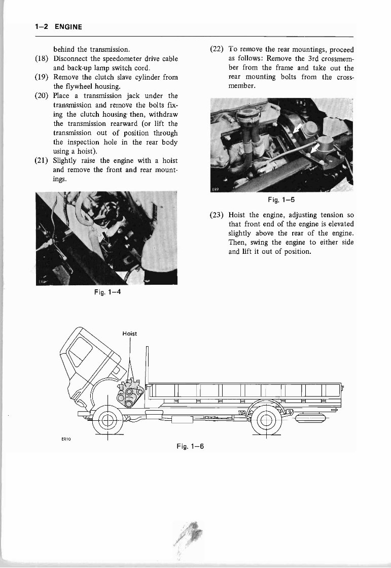
(14) Disconnect the fan drive shaft at the
water pump pulley.
Fig. 1-3
(15) Disconnect the transmission control
rods from the gearshift lever on the
floor side and from the gearshift lever
joint on the quadrant box side.
(16) Disconnect the Ist propeller shaft at
the flange yoke on the rear of the
transmission.
(17) Disconnect the parking brake control
cable at the parking brake cam lever
1-2 ENGINE
behind the transmission .
(18) Disconnect the speedometer drive cable
and back-up lamp switch cord .
(19) Remove the clutch slave cylinder from
the flywheel housing.
(20) Place a transmission jack under the
transmission and remove the bolts fix-
ing the clutch housing then , withdraw
the transmission rearward (or lift the
transmission out of position through
the inspection hole in the rear body
using a hoist).
(21) Slightly raise the engine with a hoist
and remove the front and rear mount-
ings.
Fig. 1-4
(22) To remove the rear mountings, proceed
as follows : Remove the 3rd crossmem-
ber from the frame and take out the
rear mounting bolts from the cross-
member .
Fig. 1-5
(23) Hoist the engine, adjusting tension so
that front end of the engine is elevated
slightly above the rear of the engine.
Then, swing the engine to either side
and lift it out of position.
Fig. 1-6
You're Reading a Preview
What's Included?
Fast Download Speeds
Online & Offline Access
Access PDF Contents & Bookmarks
Full Search Facility
Print one or all pages of your manual
$31.99
Viewed 75 Times Today


Secure transaction
What's Included?
Fast Download Speeds
Online & Offline Access
Access PDF Contents & Bookmarks
Full Search Facility
Print one or all pages of your manual
$31.99
Isuzu 6BB1 Diesel Engine Repair & Service Manual
The Isuzu 6BB1 Diesel Engine Repair & Service Manual is the ultimate resource for maintaining, repairing, and optimizing your 6BB1 diesel engine. Packed with detailed instructions, in-depth specifications, and user-friendly features, this manual is indispensable for both professionals and DIY enthusiasts. Explore key engine specs, troubleshooting techniques, and maintenance tips all in one comprehensive guide.
- Complete guidance: Maintain and troubleshoot the robust Isuzu 6BB1 diesel engine with step-by-step repair instructions.
- Detailed specs included: Covers torque specs, horsepower ratings, compression ratios, fuel consumption, and key engine details.
- Enhanced usability: Features in-depth diagrams, maintenance schedules, and diagnostic charts for tackling routine maintenance and major repairs.
- Built for all users: Designed for both professional mechanics and DIY enthusiasts to optimize engine performance.
- Device compatibility: Compatible with PCs, Macs, Android, and Apple devices. Requires Adobe Reader.
- Language: Available in English.
Isuzu 6BB1 Engine Specifications
| Specification | Details |
|---|---|
| Displacement | 5.8 liters |
| Horsepower | 120 HP @ 2600 RPM |
| Torque | 330 Nm @ 1600 RPM |
| Compression Ratio | 17:1 |
| Applications | Heavy-duty trucks, industrial generators |


