

ISUZU 4JJ1 4JK1 4JX1 TURBO Diesel Engine Workshop Manual
What's Included?
Fast Download Speeds
Offline Viewing
Access Contents & Bookmarks
Full Search Facility
Print one or all pages of your manual

PAGE
Section 6A Engine Mechanical .................................................................................... 1361
Section 6B Engine Cooling .......................................................................................... 1524
Section 6C Fuel System ............................................................................................... 1542
Section 6D Engine Electrical ....................................................................................... 1589
Section 6E Engine Control System ............................................................................ 1618
Section 6F Exhaust System ........................................................................................ 1986
Section 6H Engine Speed Control System ................................................................ 1998
SECTION 6
ENGINE
TABLE OF CONTENTS
ENGINE 6
4JK1/4JJ1 MODELS

ENGINE MECHANICAL (4JK1/4JJ1) 6A-1
SECTION 6A
ENGINE MECHANICAL (4JK1/4JJ1)
TABLE OF CONTENTS
ISUZU DIESEL ENGINE (4JK1/4JJ1) ................ 6A-3
Service Precautions ........................................ 6A-3
Trouble Shooting ............................................. 6A-8
Main Data and Specifications .......................... 6A-13
Special Tools ................................................... 6A-14
Engine Assembly................................................ 6A-15
Removal .......................................................... 6A-15
Installation ....................................................... 6A-17
Special Tools ................................................... 6A-19
Engine Mount ..................................................... 6A-20
Components .................................................... 6A-20
Removal .......................................................... 6A-21
Installation ....................................................... 6A-21
Torque Specifications...................................... 6A-22
Special Tools ................................................... 6A-22
Cylinder Head Cover .......................................... 6A-23
Components .................................................... 6A-23
Removal .......................................................... 6A-24
Installation ....................................................... 6A-25
Intake Manifold ................................................... 6A-27
Components (Standard Output) ...................... 6A-27
Components (High Output) ............................. 6A-28
Removal .......................................................... 6A-29
Installation ....................................................... 6A-31
Torque Specifications...................................... 6A-32
Turbocharger and Exhaust Manifold
(Standard Output) ........................................... 6A-33
Components .................................................... 6A-33
Removal .......................................................... 6A-34
Inspection ........................................................ 6A-36
Installation ....................................................... 6A-37
Torque Specifications...................................... 6A-40
Turbocharger (High Output) ............................... 6A-41
Components .................................................... 6A-41
Removal .......................................................... 6A-42
Inspection ........................................................ 6A-43
Installation ....................................................... 6A-44
Torque Specifications...................................... 6A-45
Exhaust Manifold (High Output) ......................... 6A-46
Components .................................................... 6A-46
Removal .......................................................... 6A-47
Inspection ........................................................ 6A-47
Installation ....................................................... 6A-47
Torque Specifications...................................... 6A-49
Timing Gear Train .............................................. 6A-50
Components .................................................... 6A-50
Removal .......................................................... 6A-51
Disassembly .................................................... 6A-53
Reassembly .................................................... 6A-53
Inspection ........................................................ 6A-54
Installation ....................................................... 6A-55
Torque Specifications...................................... 6A-58
Camshaft Assembly ........................................... 6A-59
Components .................................................... 6A-59
Removal .......................................................... 6A-60
Disassembly .................................................... 6A-61
Reassembly .................................................... 6A-63
Installation ....................................................... 6A-64
Torque Specifications...................................... 6A-66
Special Tools................................................... 6A-66
Valve Stem Seal and Valve Spring .................... 6A-67
Components .................................................... 6A-67
Removal .......................................................... 6A-68
Inspection ........................................................ 6A-69
Installation ....................................................... 6A-70
Special Tools................................................... 6A-71
Cylinder Head..................................................... 6A-72
Components .................................................... 6A-72
Removal .......................................................... 6A-72
Disassembly .................................................... 6A-81
Inspection ........................................................ 6A-83
Reassembly .................................................... 6A-87
Installation ....................................................... 6A-89
Torque Specifications...................................... 6A-100
Special Tools................................................... 6A-100
Piston and Connecting Rod................................ 6A-101
Components .................................................... 6A-101
Removal .......................................................... 6A-101
Disassembly .................................................... 6A-102
Reassembly .................................................... 6A-107
Installation ....................................................... 6A-108
Torque Specifications...................................... 6A-110

6A-2 ENGINE MECHANICAL (4JK1/4JJ1)
Special Tools ................................................... 6A-110
Flywheel ............................................................. 6A-111
Components .................................................... 6A-111
Removal .......................................................... 6A-111
Inspection ........................................................ 6A-113
Installation ....................................................... 6A-113
Torque Specifications...................................... 6A-115
Special Tools ................................................... 6A-115
Gear Case Assembly ......................................... 6A-116
Components .................................................... 6A-116
Removal .......................................................... 6A-117
Installation ....................................................... 6A-118
Torque Specifications...................................... 6A-119
Crankshaft Front Oil Seal ................................... 6A-120
Components .................................................... 6A-120
Removal .......................................................... 6A-120
Installation ....................................................... 6A-121
Torque Specifications...................................... 6A-122
Special Tools ................................................... 6A-122
Crankshaft Rear Oil Seal ................................... 6A-123
Components .................................................... 6A-123
Removal .......................................................... 6A-124
Installation ....................................................... 6A-124
Special Tools ................................................... 6A-125
Crankshaft .......................................................... 6A-126
Components .................................................... 6A-126
Removal .......................................................... 6A-127
Disassembly .................................................... 6A-127
Reassembly..................................................... 6A-128
Inspection ........................................................ 6A-128
Installation ....................................................... 6A-132
Torque Specifications...................................... 6A-135
Cylinder Block .................................................... 6A-136
Components .................................................... 6A-136
Removal .......................................................... 6A-136
Inspection ........................................................ 6A-137
Installation ....................................................... 6A-139
Lubrication System ............................................. 6A-140
Service Precautions ........................................ 6A-140
Functional Check ............................................ 6A-141
Oil Filter Cartridge .............................................. 6A-143
Components .................................................... 6A-143
Removal .......................................................... 6A-143
Installation ....................................................... 6A-143
Special Tools ................................................... 6A-144
Oil Filter Assembly and Oil Cooler ..................... 6A-145
Components .................................................... 6A-145
Removal .......................................................... 6A-145
Disassembly .................................................... 6A-146
Reassembly..................................................... 6A-147
Installation ....................................................... 6A-147
Crank Case and Oil Pan .................................... 6A-150
Components .................................................... 6A-150
Removal .......................................................... 6A-151
Disassembly .................................................... 6A-152
Reassembly .................................................... 6A-152
Installation ....................................................... 6A-153
Torque Specifications...................................... 6A-155
Oil Pump ............................................................ 6A-156
Components .................................................... 6A-156
Removal .......................................................... 6A-156
Disassembly .................................................... 6A-157
Reassembly .................................................... 6A-158
Inspection ........................................................ 6A-158
Installation ....................................................... 6A-159
Oil Pressure SW ................................................ 6A-161
Components .................................................... 6A-161
Removal .......................................................... 6A-162
Inspection ........................................................ 6A-162
Installation ....................................................... 6A-162
Circuit check.................................................... 6A-162
Air Cleaner Element ........................................... 6A-163
Removal .......................................................... 6A-163
Cleaning .......................................................... 6A-163
Installation ....................................................... 6A-163

ENGINE MECHANICAL (4JK1/4JJ1) 6A-3
ISUZU DIESEL ENGINE (4JK1/4JJ1)
Service Precautions
Matters that require attention in terms of
maintenance
To prevent damage to the engine and ensure reliability
of its performance, pay attention to the following in
maintaining the engine:
• When lifting up or supporting the engine, do not
apply a jack on the oil pan.
When taking down the engine on the ground, do
not make the bearing surface of the oil pan touch
the ground directly. Use a wooden frame, for
example, to support the engine with the engine
foot and the flywheel housing.
Because there is only a small clearance between
the oil pan and the oil pump strainer, it can
damage the oil pan and the oil strainer.
• When the air duct or air cleaner is removed, cover
the air intake opening to prevent foreign matter
from getting into the cylinder. If it gets
contaminated, it can considerably damage the
cylinder and others while the engine is operating.
• When maintaining the engine, never fail to remove
the battery earth cable. If not, it may damage the
wire harness or electrical parts. If you need
electricity on for the purpose of inspection, for
instance, watch out for short circuits and others.
• Apply engine oil to the sliding contact surfaces of
the engine before reassembling it. This ensures
adequate lubrication when the engine is first
started.
• When valve train parts, pistons, piston rings,
connecting rods, connecting rod bearings or
crankshaft journal bearings are removed, put them
in order and keep them.
• When installing them, put them back in the same
location they were removed from.
• Gaskets, oil seals, O-rings, etc. must be replaced
with new ones when the engine is reassembled.
• As for parts where a liquid gasket is used, remove
an old liquid gasket completely and clean it up
thoroughly so that no oil, water or dust is clinging
to them. Then, apply the designated liquid gasket
to each place anew before assembly.
• Surfaces covered with liquid gasket must be
assembled within 5 minutes of gasket application.
If more than 5 minutes has elapsed, remove the
existing liquid gasket and apply a new liquid
gasket.
• When assembling or installing parts, fasten them
with the prescribed tightening torque so that they
are installed properly.
Matters that require attention in specifically dealing
with this engine.
Holes or clearances in the fuel system, which serve as
a passage of fuel, including the inside of the injector,
are made with extreme precision. For this reason, they
are highly sensitive to foreign matter and, if it gets in, it
can lead to an accident on the road, for instance; thus,
make sure that foreign matter is prevented from getting
in.
When servicing the fuel system, every precaution must
be taken to prevent the entry of foreign material into the
system.
• Before beginning the service procedure, wash the
fuel line and the surrounding area.
• Perform the service procedures with clean hands.
Do not wear work gloves.
• Immediately after removing the fuel hose and/or
fuel pipe, carefully tape vinyl bags over the
exposed ends of the hose or pipe.
• If parts are to be replaced (fuel hose, fuel pipe,
etc.) do not open the new part packaging until
installation.
Work procedure
• The fuel opening must be quickly sealed when
removing the fuel pipe, injection pipe, fuel injector,
fuel supply pump, and fuel rail.
• The eyebolts and gasket must be stored in a clean
parts box with a lid to prevent adhesion of foreign
matter.
• Fuel leakage could cause fires. Therefore, after
finishing the work, wipe off the fuel that has leaked
out and make sure there is no fuel leakage after
starting the engine.
6A-4 ENGINE MECHANICAL (4JK1/4JJ1)
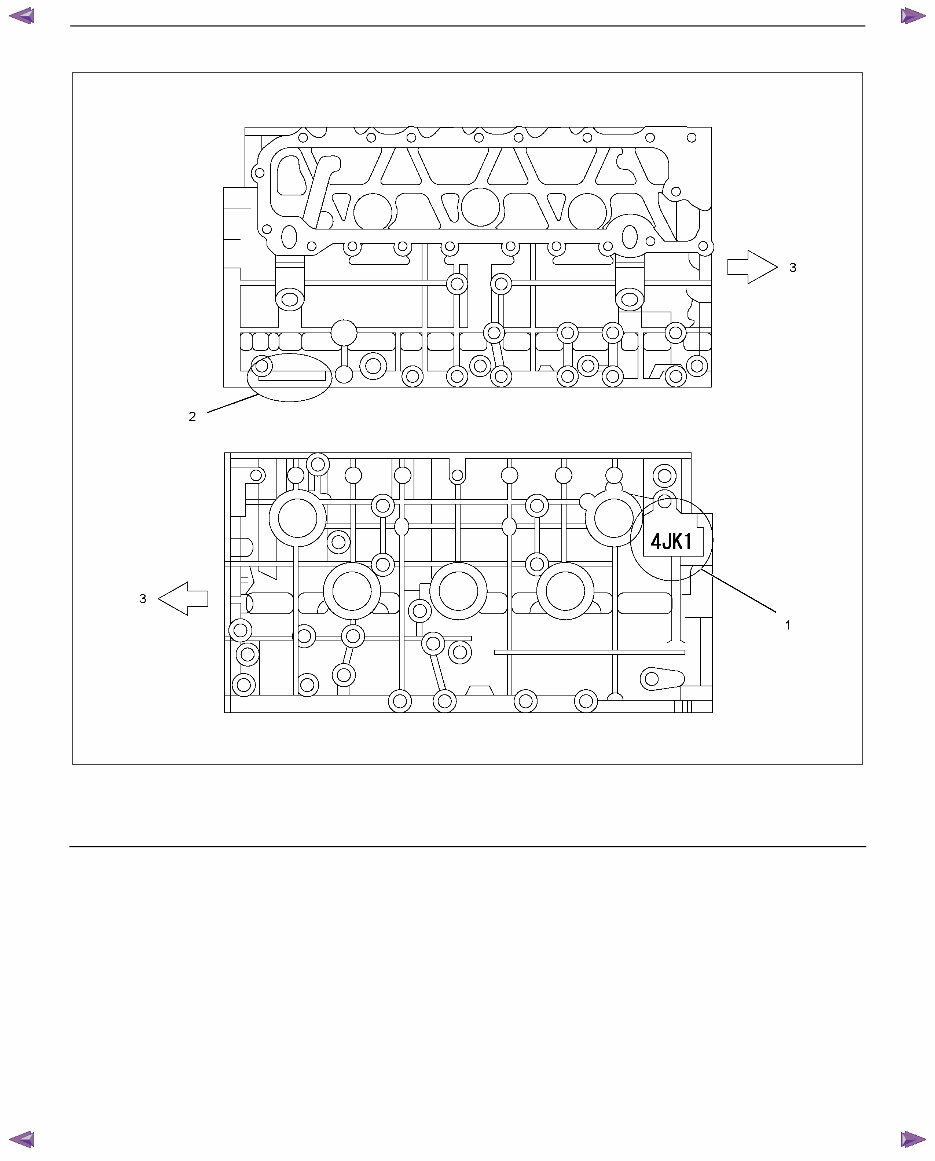
How to read the model (This illustration is 4JK1 engine)
RTW56ALF004701
Legend
1. Engine Model (Stamped)
2. Engine Number (Stamped)
3. Front
Explanation of functions and operations
Electronic engine control
With the control unit, the range from injection to air
intake/exhaust, including fuel injection quantity, injection
timing, intake air restriction, EGR, and idling rpm, is
controlled.
Piston
The piston is aluminum-alloy and a thermal flow piston
with a strut cast, while the combustion chamber is a
round reentrant type.
Cylinder head
The cylinder head is aluminum-alloy and there are 4
valves per cylinder. The angular tightening method of
the cylinder head bolt further increases reliability and
durability.
You're Reading a Preview
What's Included?
Fast Download Speeds
Offline Viewing
Access Contents & Bookmarks
Full Search Facility
Print one or all pages of your manual
$37.99
$49.99
Viewed 25 Times Today


Secure transaction
What's Included?
Fast Download Speeds
Offline Viewing
Access Contents & Bookmarks
Full Search Facility
Print one or all pages of your manual
$37.99
$49.99
This workshop service repair manual covers the following turbo diesel engines:
- 2.5L 4-cylinder, 4-cycle, water-cooled, DOHC, Isuzu 4JK1 turbo diesel engine
- 3.0L 4-cylinder, 4-cycle, water-cooled, DOHC, Isuzu 4JJ1 turbo diesel engine
- 3.0L 4-cylinder, 4-cycle, water-cooled, DOHC, Isuzu 4JX1 turbo diesel engine
The manual includes the following content:
- Main data and specifications
- Torque specifications
- Engine mechanical
- Air cleaner system
- Lubricating system
- Fuel system
- Cooling system
- Valve clearance adjustment
- Compression pressure measurement
- Engine removal
- Engine installation
- Engine warm-up
- Engine repair kit
- Engine overhaul
- Engine cooling
- Fuel system
- Engine driveability
- Emission system
- Intercooler system
- Intake throttle valve
- Intake manifold
- Engine electrical
- Generator system
- Starter motor system
- Pre-heating system
- Glow relay-glow plug
- EGR system
- Engine control system
- ECM connector system
- Turbocharger system
- Accelerator control
- Troubleshooting
- Special tools
- Wiring diagram
This comprehensive manual provides detailed exploded views and step-by-step procedures with illustrations, making it suitable for both professional mechanics and DIY enthusiasts. It is fully printable, allowing easy access to specific pages or the entire manual for repairs, maintenance, and servicing needs.


