

FOREWORD
This manual contains repair procedures for the DUTRO.
Applicable models: WU300, 340, 410 series
XZU404, 412, 414, 422, 424, 434 series
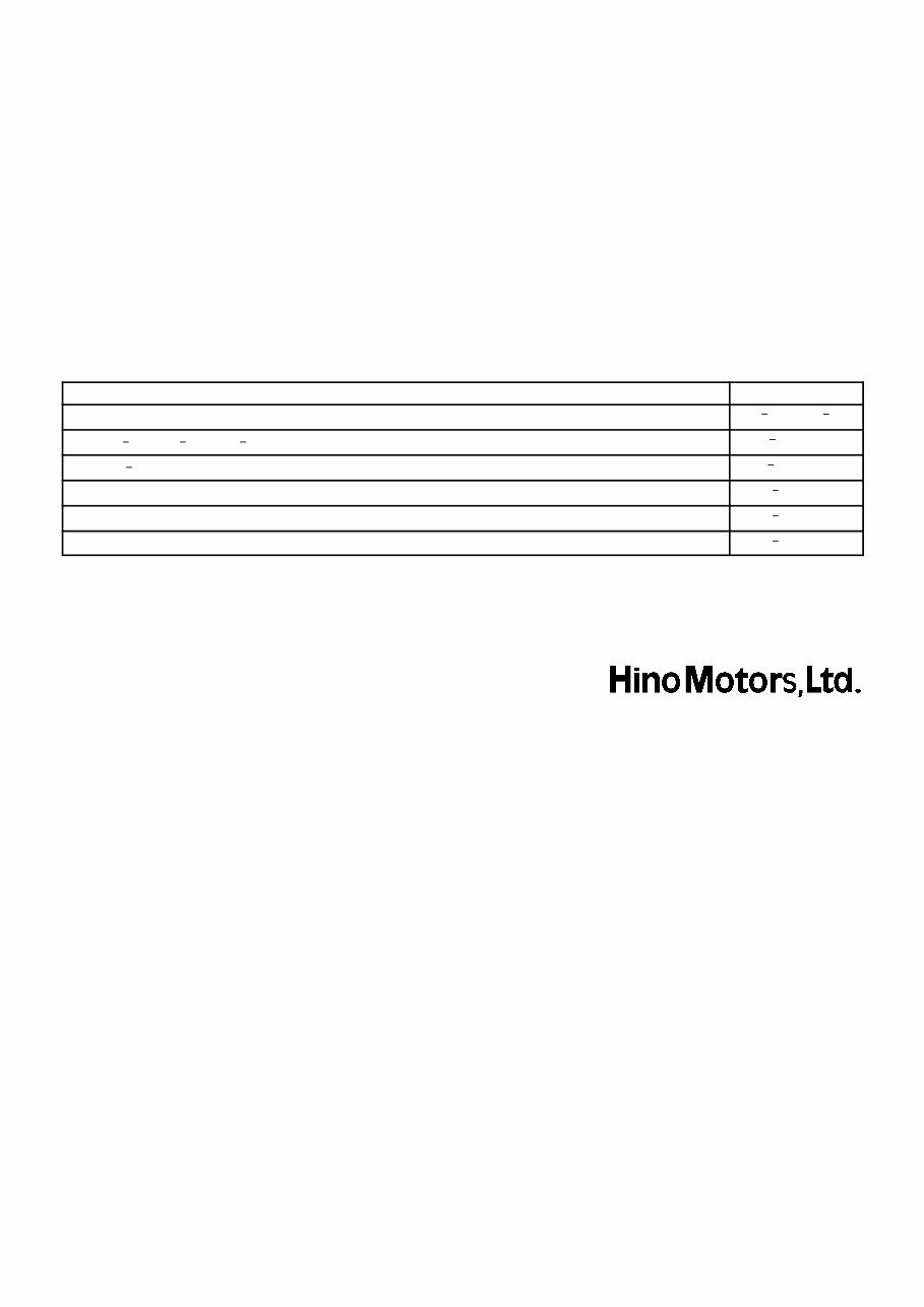
Manual Name Pub. No.
S DUTRO Electrical Wiring Diagram
S1 YXZE05A SL
S S05C B, S05C TA, S05C TB Engine Workshop Manual
S5 YS05E06A
S W04D J Engine Workshop Manual
S5 YW04E06A
S H260 Manual Transmission Workshop Manual
S1 YXZE07A
S H350 Manual Transmission Workshop Manual
S1 YXZE06A
S M150, M153 Manual Transmission Workshop Manual
S1 YXZE08A
All information in this manual is based on the latest product information at the time of publication. However,
specifications and procedures are subject to change without notice.

CAUTION
This manual does not include all the necessary items about repair and service. This manual is made
for the purpose of the use for the persons who have special techniques and certifications. In the
cases that non specialized or uncertified technicians perform repair or service only using this manu-
al or without proper equipment or tool, that may cause severe injury to you or other people around
and also cause damage to your customer’s vehicle.
In order to prevent dangerous operation and damages to your customer’s vehicle, be sure to follow
the instruction shown below.
S Must read this manual thoroughly. It is especially important to have a good understanding of
all the contents written in the PRECAUTION of ”IN” section.
S The service method written in this manual is very effective to perform repair and service. When
performing the operations following the procedures using this manual, be sure to use tools spe-
cified and recommended. If using non specified or recommended tools and service method,
be sure to confirm safety of the technicians and any possibility of causing personal injury or
damage to the customer’s vehicle before starting the operation.
S If part replacement is necessary, must replace the part with the same part number or equivalent
part. Do not replace it with inferior quality.
S It is important to note that this manual contains various ”Cautions” and ”Notices” that must be
carefully observed in order to reduce the risk of personal injury during service or repair, or the
possibility that improper service or repair may damage the vehicle or render it unsafe. It is also
important to understand that these ”Cautions” and ”Notices” are not exhaustive, because it is
important to warn of all the possible hazardous consequences that might result from failure to
follow these instructions.

60

SEAT BELT
LIGHTING
WIPER & WASHER
AUDIO & VISUAL SYSTEM
WIRING
COMMUNICATION SYSTEM
WINDSHIELD/WINDOWGLASS/MIRROR
INSTRUMENT PANEL/METER
SEAT
THEFT DETERRENT & DOOR LOCK
ENGINE HOOD/DOOR
EXTERIOR/INTERIOR TRIM
VEHICLE CONTROL SYSTEM
POWER TAKE OFF
ALPHABETICAL INDEX
61
65
66
67
68
69
70
71
72
73
75
76
80
87
61
65
66
67
68
69
70
71
72
73
75
76
80
87

INTRODUCTION
HOW TO USE THIS MANUAL 01 1 .............
GENERAL INFORMATION 01 1 ..................
IDENTIFICATION INFORMATION 01 4 ..........
VEHICLE IDENTIFICATION AND
SERIAL NUMBERS 01 4 ......................
REPAIR INSTRUCTION 01 5 ...................
PRECAUTION 01 5 ............................
VEHICLE LIFT AND
SUPPORT LOCATIONS 01 14 ..................
HOW TO TROUBLESHOOT ECU
CONTROLLED SYSTEMS 01 16 ...............
GENERAL INFORMATION 01 16 ..................
HOW TO PROCEED WITH
TROUBLESHOOTING 01 17 ....................
ELECTRONIC CIRCUIT INSPECTION
PROCEDURE 01 27 ...........................
TERMS 01 32 .................................
ABBREVIATIONS USED IN THIS MANUAL 01 32 ...
GLOSSARY OF SAE AND HINO TERMS 01 37 .....
0108R 05
N17080
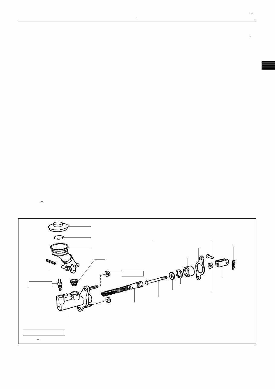
Filler Cap
Float
Reservoir Tank
z Grommet
Clip
Slotted Spring Pin
: Specified torque
z Non reusable part
Cylinder
Piston
Push Rod
Washer
Snap Ring
Boot
z Gasket
Lock Nut
Clevis Pin
Clevis
N·m (kgf·cm, ft·lbf)
12 (120, 9)
15 (155, 11)
INTRODUCTION HOW TO USE THIS MANUAL
01 1
HOW TO USE THIS MANUAL
GENERAL INFORMATION
1. GENERAL DESCRIPTION
(a) This manual is made in accordance with SAE J2008.
(b) Generally, repair operations can be separated in the following 3 main processes:
1. Diagnosis
2. Removing/Installing, Replacing, Disassembling/Reassembling, Checking and Adjusting
3. Final Inspection
(c) This manual explains the 1st process of ”Diagnosis” (found in the ”Diagnostics” section), the 2nd pro-
cess of ”Removing and Installing, Replacing, Disassembling, Installing and Checking, Adjusting”, but
the 3rd process of ”Final Inspection” is omitted.
(d) The following essential operations are not written in this manual. However, these operations must be
performed in actual situations.
(1) Operations with a jack or lift
(2) Cleaning of a removed part when necessary
(3) Visual check
2. INDEX
(a) An alphabetical INDEX section is provided at the end of the book (4/4) to guide you to the item to be
repaired.
3. PREPARATION
(a) Use of special service tools (SST) and special service materials (SSM) may be required, depending
on the repair situation. Be sure to use SST and SSM when they are required and follow the working
procedure properly. A list of SST and SSM is in the Preparation section of this manual.
4. REPAIR PROCEDURES
(a) Component drawing is placed under the title where necessary.
(b) Non reusable parts, grease application area, precoated parts and tightening torque are specified in
the components drawing.
Example:
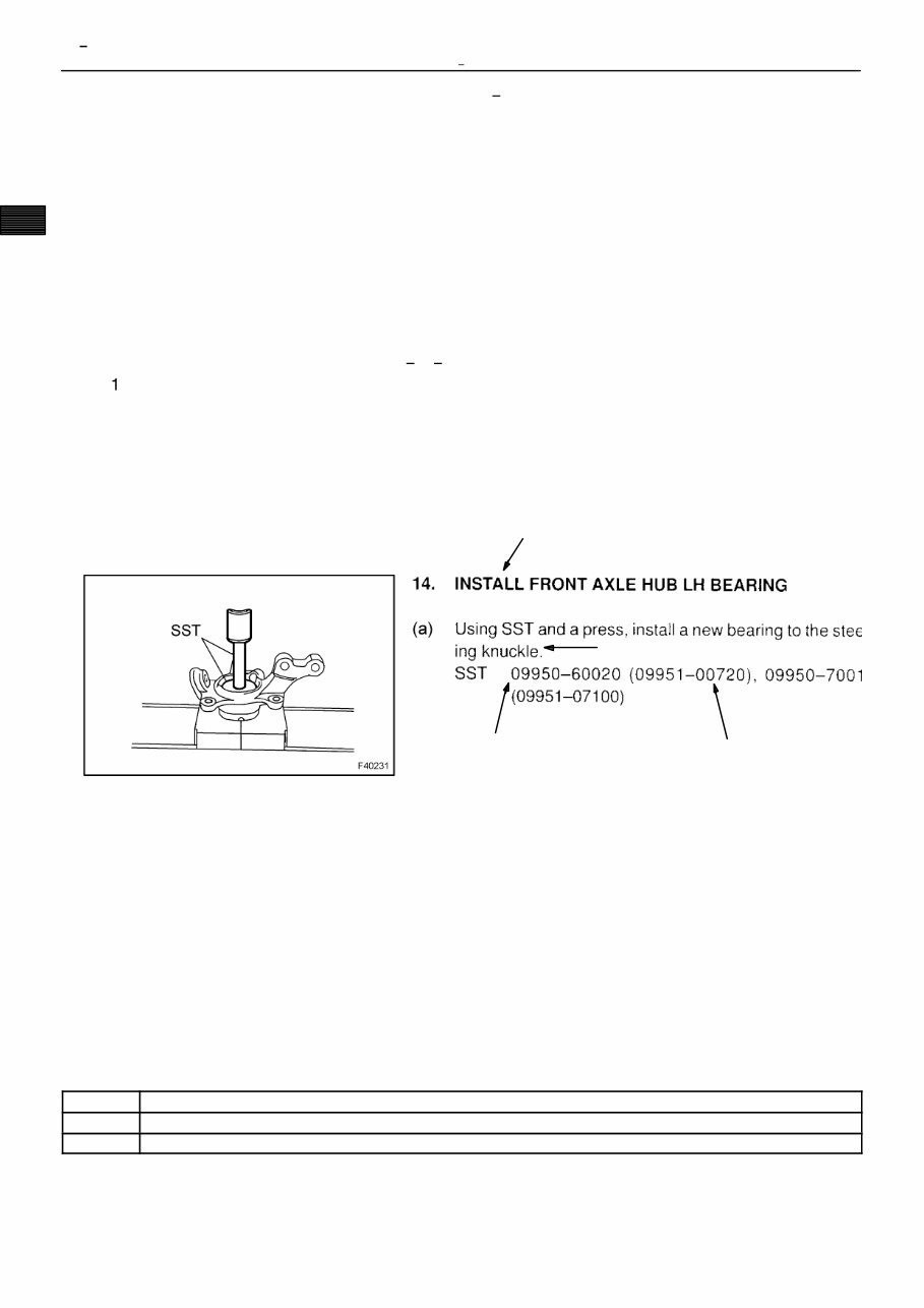
Illustration:
what to do and where
Component part No.
Detailed test: how to perform task
Task heading: what to do
Set part No
Illustration:
what to do and where
D26745
01 2
INTRODUCTION HOW TO USE THIS MANUAL
(c) Tightening torque, grease application area, and non reusable parts are described as important points
in the procedures.
NOTICE:
There are cases where such information can only be indicated by an illustration. In those cases, all
the information such as torque, oil, etc. are described in the illustration.
(d) Installing procedures are performed in the reverse order of the removal, and only the important points
are described.
(e) Only items with points are described in the procedure, and the operational portion and content are
placed using an illustration. In the explanations, details of the operational method, standard value and
notice are placed.
(f) There may be a case where the illustrations of similar models are used. In that case, specific details
may be different from the actual vehicle.
(g) The procedures are presented in a step by step format:
() The illustration shows what to do and where to do it.
(2) The task heading tells what to do.
(3) The explanation text tells how to perform the task and gives other information such as specifica-
tions and warnings.
Example:
HINT:
This format provides an experienced technician with a FAST TRACK to the necessary information. The task
heading can be read at a glance when necessary, and the text below provides detailed information. Impor-
tant specifications and warnings always stand out in bold type.
5. SERVICE SPECIFICATIONS
(a) Specifications are presented in bold type throughout the manual. You never have to leave the proce-
dure to look up your specifications. The specifications are also found in the Service Specifications sec-
tion for a quick reference.
6. TERMS DEFINITION
CAUTION Indicates the possibility of injury to you or other people.
NOTICE Indicates the possibility of damage to the components being repaired.
HINT Provides additional information to help you to perform the repair efficiently.

INTRODUCTION HOW TO USE THIS MANUAL
01 3
7. SI UNIT
(a) The units given in this manual are primarily expressed according to the SI UNIT (International System
of Units), and alternately expressed in the metric system and in the English System.
Example:
Torque: 30 N m (310 kgf cm, 22 ft lbf)
010CB 03
D30383
B
A
C
D30384
B
A
C
01 4
INTRODUCTION IDENTIFICATION INFORMATION
IDENTIFICATION INFORMATION
VEHICLE IDENTIFICATION AND SERIAL NUMBERS
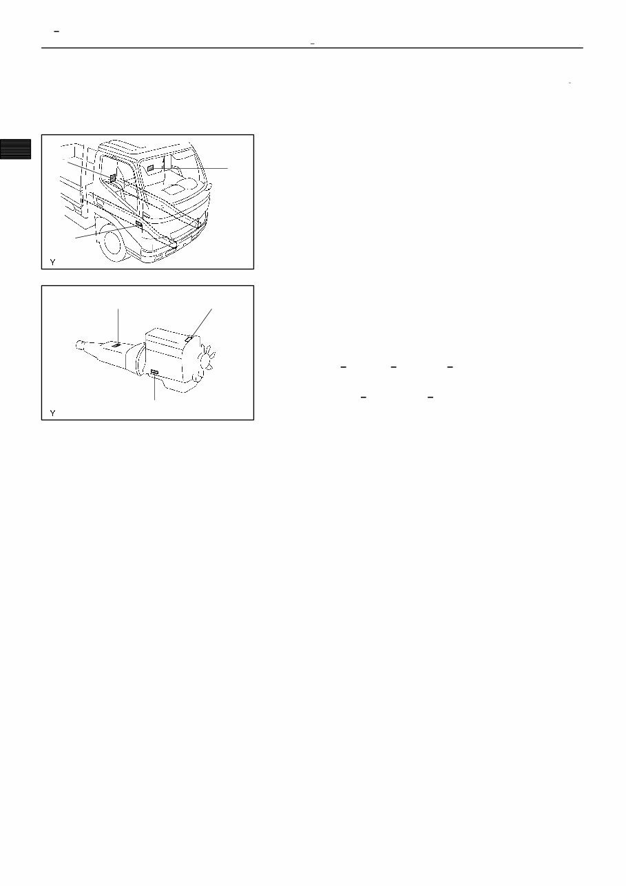
1. VEHICLE IDENTIFICATION NUMBER
(a) The vehicle identification number is stamped on the right
frame. as shown in the illustration. This number has also
been stamped on the manufacturer’s plate.
A: Vehicle Identification Number
B: Manufacturer’s Plate
C: Manufacturer’s Plate (Regular cab LHD)
2. ENGINE SERIAL NUMBER AND TRANSMISSION SE-
RIAL NUMBER
(a) The engine serial number is stamped on the cylinder
block of the engine, and the transmission serial number
is stamped on the housing, as shown in the illustration.
A: S05C B, S05C TA, S05C TB
B: H260, H350, H351, M150, M153
C: 14B, 15B FTE, W04D J
010KH 01
5
4
3
6
2
1
D20200
INTRODUCTION REPAIR INSTRUCTION
01 5
REPAIR INSTRUCTION
PRECAUTION
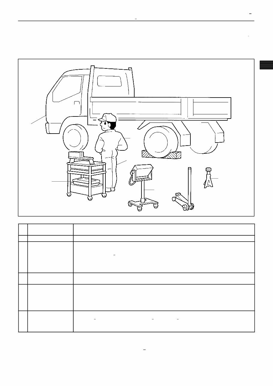
1. BASIC REPAIR HINT
(a) HINTS ON OPERATIONS
1 Looks
S Always wear a clean uniform.
S Hat and safety shoes must be worn.
2 Vehicle protection S Set a grill cover, fender cover, seat cover and floor mat before starting operation.
3 Safe operation
S When working with 2 or more persons, be sure to check the safety of one another.
S When working with the engine running, pay attention to the ventilation in the workshop.
S When working on high temperature, rotating, moving and vibrating parts, be careful not to burn or injure
yourself.
S When jacking up the vehicle, be sure to support the specified location with a safety stand.
S When lifting up the vehicle, use safety equipment.
4
Preparation of tools and
measuring gauge
S Before starting repairs, prepare the tool stand, SST, gauge, oil, shop rag and parts for replacement.
5
Removal and installation,
disassembly and assem-
bly operations
S Diagnose with a thorough understanding of the trouble condition and perform effective operation.
S Before removing the parts, check the general condition of the assembly, and for deformation and damage.
S When the structure is complicated, take a note or make matchmarks as not to make mistakes that affect the
function of the parts.
S Clean and wash the removed parts if necessary, and assemble them after a thorough check.
6 Removed parts
S Place the removed parts in the correct order to avoid mixing them up or making them dirty.
S As for non reusable parts such as gaskets, O rings, and self locking nuts, replace them with new ones
following the instructions in this manual.
S Organize the parts that were replaced in a box and show them to the customer.
(b) JACKING UP AND SUPPORTING VEHICLE
(1) Care must be taken when jacking up and supporting the vehicle. Be sure to lift and support the
vehicle at the proper locations (See page 01 14).
You're Reading a Preview
What's Included?
 Lifetime Access
Fast Download Speeds
Online & Offline Access
Access PDF Contents & Bookmarks
Full Search Facility
Print one or all pages of your manual
$41.99
Hino Dutro WU300, 340, 410, XZU404, 412, 422, 434 Series Engine Chassis & Electrical Complete Workshop Service Repair Manual
Viewed 14 Times Today

What's Included?
Lifetime Access
Fast Download Speeds
Online & Offline Access
Access PDF Contents & Bookmarks
Full Search Facility
Print one or all pages of your manual
$41.99

Secure transaction
What's Included?
Lifetime Access
Fast Download Speeds
Online & Offline Access
Access PDF Contents & Bookmarks
Full Search Facility
Print one or all pages of your manual
Description
This complete workshop service repair manual is designed for the Hino Dutro WU300, 340, 410, XZU404, 412, 422, 434 series engine chassis & electrical systems.
Whether you are a professional mechanic or a DIY enthusiast, this comprehensive manual provides detailed service and repair procedures for significant cost savings.
Key features include:
- Step-by-step instructions
- Illustrative pictures
- Models covered: All Models/Engines/Trim/Transmissions Types
- Complete coverage of repair procedures A-Z
- Compatibility with all PC & MAC Computers, tablets, and mobile phones
- Requires only Adobe Reader software
- Instant delivery via email after payment
- Customer satisfaction guaranteed


