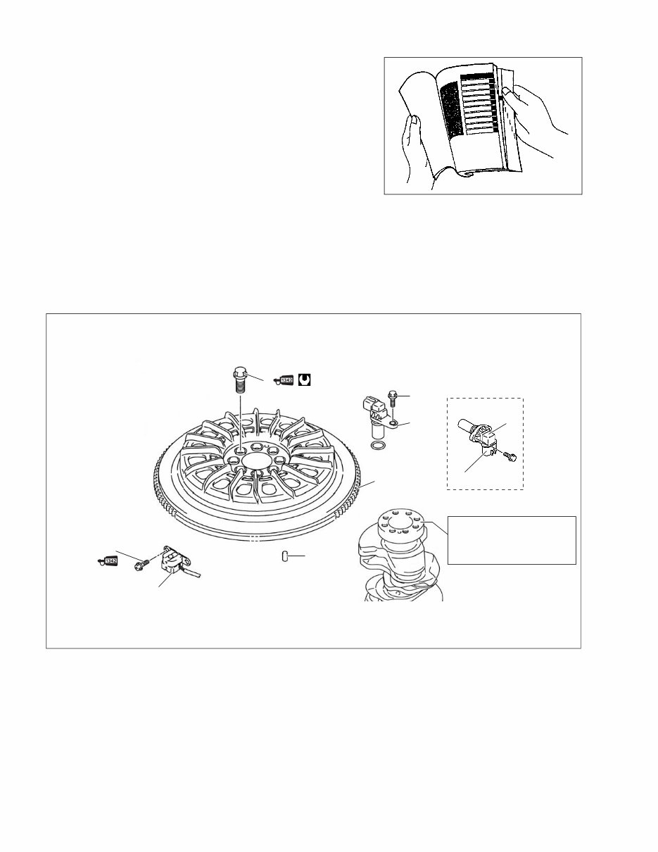
HOW TO USE THIS MANUAL TO LOCATE WHAT YOU ARE LOOKING FOR: 1. The text of this manual is divided into sections. 2. The section titles are listed on the previous page in a GROUP INDEX. Select the section needed for reference. 3. Holding the manual as shown at the right will allow you to find the first page of the section easily. 4. The first page of each section contains a table of contents to easily locate the item and page you need. COMPONENT PARTS AND IMPORTANT ITEM ILLUSTRATIONS Under the name of each system or unit, an exploded view is provided with work instructions and other ser- vice information such as the tightening torque, lubrication and locking agent points. Example: 5 4 3 2 7 7 6 6 1 118 N·m (11.8 kg-m, 85.3 lb-ft) 1. Flywheel bolt 2. Flywheel 3. Dowel pin 4. CKP sensor 5. Bolt 6. CMP sensor 7. Bolt NOTE: Clean flywheel and crankshaft mating surfaces with cleaning solvent.
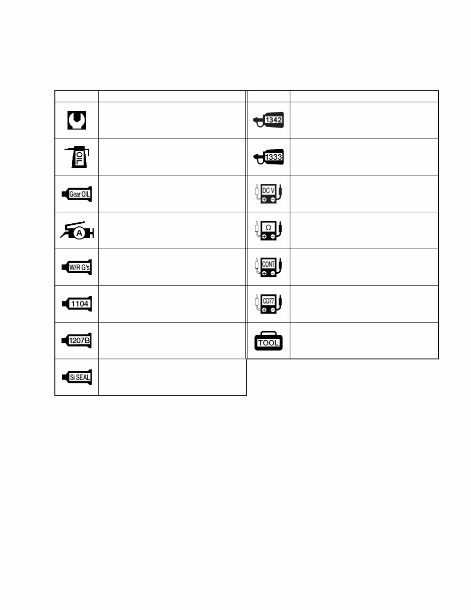
SYMBOL Listed in the table below are the symbols indicating instructions and other important information necessary for proper servicing. Please note the definition for each symbol. You will find these symbols used throughout this manual. Refer back to this table if you are not sure of any symbol(s) meanings. SYMBOL DEFINITION SYMBOL DEFINITION Torque control required. Data beside it indicates specified torque. Apply THREAD LOCK “1342”. Apply oil. Use the engine oil unless oth- erwise specified. Apply THREAD LOCK SUPER “1333B”. Apply SUZUKI OUTBOARD MOTOR GEAR OIL. Measure in DC voltage range. Apply SUZUKI SUPER GREASE “A”. Measure in resistance range. Apply SUZUKI WATER RESISTANT GREASE. Measure in continuity test range. Apply SUZUKI BOND “1104”. Use peak voltmeter “Stevens CD-77”. Apply SUZUKI BOND “1207B”. Use special tool. Apply SUZUKI SILICONE SEAL.
ABBREVIATIONS Abbreviations used in this service manual are as follows: BTDC : Before Top Dead Center CKP : Crankshaft position CMP : Camshaft position CTP : Close Throttle position DC : Direct Current DOHC : Double Over Head Camshaft ECM : Engine Control Module EX (Ex.) : Exhaust IAC : Idle Air Control IAT : Intake Air Temperature IN (In.) : Intake MAP : Manifold absolute pressure OCV : Oil control valve PCV : Positive Crankcase Ventilation PORT : Port PTT : Power Trim & Tilt SPS : Shift Position Sensor STBD : Starboard TPS : Throttle Position Sensor VSV : Vacuum switching valve VVT : Variable Valve Timing
1 GENERAL INFORMATION 1-1 CONTENTS GENERAL INFORMATION WARNING/CAUTION/NOTE .........................................................................1- 2 GENERAL PRECAUTIONS ...........................................................................1- 2 IDENTIFICATION NUMBER LOCATION ......................................................1- 4 FUEL AND OIL ..............................................................................................1- 5 GASOLINE RECOMMENDATION .........................................................1- 5 ENGINE OIL ...........................................................................................1- 5 ENGINE BREAK-IN .......................................................................................1- 6 WARM-UP RECOMMENDATION ..........................................................1- 6 THROTTLE RECOMMENDATION .........................................................1- 6 PROPELLERS ...............................................................................................1- 7 POWERHEAD DIRECTION OF ROTATION .................................................1- 8 CYLINDER NUMBER ....................................................................................1- 8 * SPECIFICATIONS .......................................................................................1- 9 * SERVICE DATA ..........................................................................................1-13 TIGHTENING TORQUE .................................................................................1-21 SPECIAL TOOLS ..........................................................................................1-23 MATERIALS REQUIRED ..............................................................................1-27
1-2 GENERAL INFORMATION WARNING/CAUTION/NOTE Please read this manual and follow its instructions carefully. To emphasize special information, the symbol and the words WARNING, CAUTION and NOTE have special meanings. Pay special attention to the mes- sages highlighted by these signal words. ! Indicates a potential hazard that could result in death or injury. " Indicates a potential hazard that could result in motor damage. NOTE: Indicates special information to make maintenance easier or instructions clearer. Please note, however, that the warnings and cautions contained in this manual cannot possibly cover all potential hazards relating to the servicing, or lack of servicing, of the outboard motor. In addition to the WARNING and CAUTION stated, you must also use good judgement and observe basic mechanical safety principles. GENERAL PRECAUTIONS ! • Proper service and repair procedures are important for the safety of the service mechanic and the safety and reliability of the outboard motor. • To avoid eye injury, always wear protective goggles when filing metals, working on a grinder, or doing other work, which could cause flying material particles. • When two or more persons work together, pay attention to the safety of each other. • When it is necessary to run the outboard motor indoors, make sure that exhaust gas is vented outdoors. • When testing an outboard motor in the water and on a boat, ensure that the necessary safety equipment is on board. Such equipment includes: flotation aids for each person, fire extin- guisher, distress signals, anchor, paddles, bilge pump, first-aid kit, emergency starter rope, etc. • When working with toxic or flammable materials, make sure that the area you work in is well- ventilated and that you follow all of the material manufacturer’s instructions. • Never use gasoline as a cleaning solvent. • To avoid getting burned, do not touch the engine, engine oil or exhaust system during or shortly after engine operation. • Oil can be hazardous. Children and pets may be harmed from contact with oil. Keep new and used oil away from children and pets. To minimize your exposure to oil, wear a long sleeve shirt and moisture-proof gloves (such as dishwashing gloves) when changing oil. If oil con- tacts your skin, wash thoroughly with soap and water. Launder any clothing or rags if wet with oil. Recycle or properly dispose of used oil. • After servicing fuel, oil/engine cooling system and exhaust system, check all lines and fit- tings related to the system for leaks. • Carefully adhere to the battery handling instructions laid out by the battery supplier.
GENERAL INFORMATION 1-3 " • If parts replacement is necessary, replace the parts with Suzuki Genuine Parts or their equiv- alent. • When removing parts that are to be reused, keep them arranged in an orderly manner so that they may be reinstalled in the proper order and orientation. • Be sure to use special tools when instructed. • Make sure that all parts used in assembly are clean and also lubricated when specified. • When use of a certain type of lubricant, bond or sealant is specified, be sure to use the speci- fied type. • When removing the battery, disconnect the negative cable first and then the positive cable. When reconnecting the battery, connect the positive cable first and then the negative cable. • When performing service to electrical parts, if the service procedures do not require using battery power, disconnect the negative cable at the battery. • Tighten cylinder head and case bolts and nuts, beginning with larger diameter and ending with smaller diameter. Always tighten from inside to outside diagonally to the specified tight- ening torque. • Whenever you remove oil seals, gaskets, packing, O-rings, locking washers, locking nuts, cotter pins, circlips, and certain other parts as specified, always replace them with new. Also, before installing these new parts, be sure to remove any left over material from the mating surfaces. • Never reuse a circlip. When installing a new circlip, take care not to expand the end gap larger than required to slip the circlip over the shaft. After installing a circlip, always ensure that it is completely seated in its groove and securely fitted. • Use a torque wrench to tighten fasteners to the torque values when specified. • Remove grease or oil from screw/bolt threads unless a lubricant is specified. • After assembly, check parts for tightness and operation. • To protect the environment, do not unlawfully dispose of used motor oil, other fluids and bat- teries. • To protect the Earth’s natural resources, properly dispose of used motor parts.
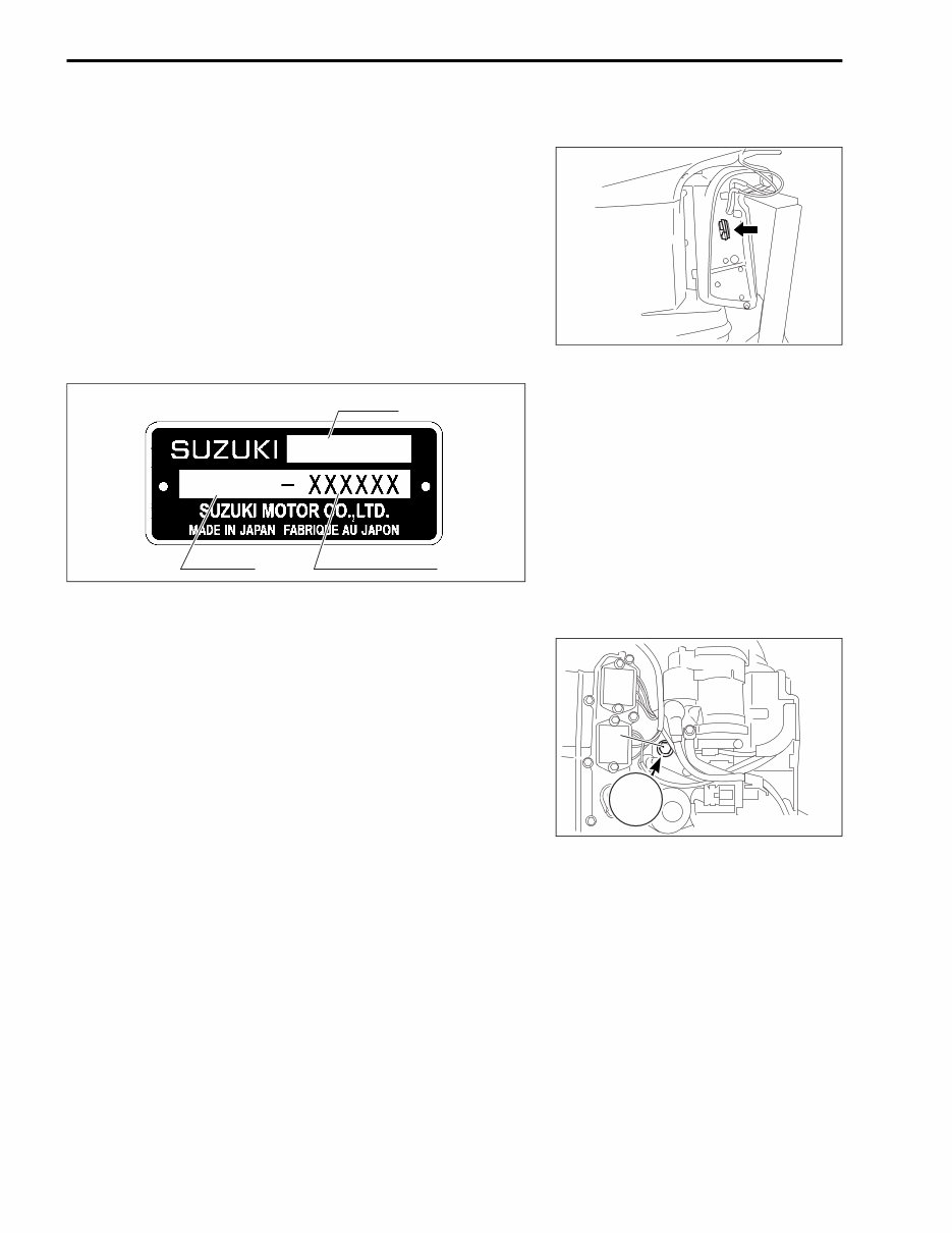
1-4 GENERAL INFORMATION IDENTIFICATION NUMBER LOCATION MODEL, PRE-FIX, SERIAL NUMBER The MODEL, PRE-FIX and SERIAL NUMBER of motor are stamped on a plate attached to the clamp bracket. Example ENGINE SERIAL NUMBER A second engine serial number plate is pressed into a boss on the cylinder block. MODEL PRE-FIX SERIAL NUMBER DF 250 25001F XXXXXX 1. Serial number plate 1
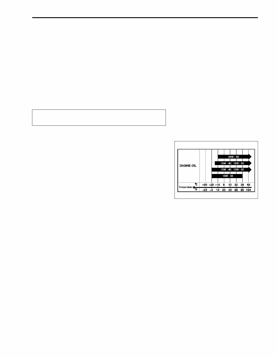
GENERAL INFORMATION 1-5 FUEL AND OIL GASOLINE RECOMMENDATION Suzuki highly recommends that you use alcohol-free unleaded gasoline with a minimum pump octane rating of 87 (R/2+M/2 method) or 91 (Research method). However, blends of unleaded gasoline and alcohol with equivalent octane content may be used. Allowable maximum blend of a single additive (not combination): 5% Methanol, 10% Ethanol, 15% MTBE " ENGINE OIL Use only oils that are rated SE, SF, SG, SH or SJ under the API (American Petroleum Institute) classification system. The viscosity rating should be SAE 10W-40. If SAE 10W-40 motor oil is not available, select an alternative according to the chart at right. If leaded gasoline is used, engine damage may result. Use only unleaded gasoline.
Discover the comprehensive guide for maintaining and repairing the 2004-2014 Suzuki DF200/DF225/DF250 4-Stroke V6 Outboards – engines renowned for their remarkable power, efficiency, and durability in a wide range of marine applications. Designed to meet the needs of both professional technicians and dedicated boating enthusiasts, these manuals equip you with the knowledge to perform detailed diagnostic, repair, and maintenance procedures.
This essential manual walks you through system overviews, step-by-step instructions on engine servicing, and troubleshooting tips unique to Suzuki’s robust outboard series. With clearly illustrated schematics and in-depth technical insights, you can confidently manage everything from routine maintenance to complex repair tasks.
2004-2014 Suzuki DF200/DF225/DF250 4-Stroke V6 Outboards OEM Service & Repair Manual is your ultimate resource for understanding the intricate workings of these advanced engines, ensuring optimal performance and longevity.