

General Motors STG 6.5L V8 Turbo Diesel Engine Student Workbook
What's Included?
Fast Download Speeds
Offline Viewing
Access Contents & Bookmarks
Full Search Facility
Print one or all pages of your manual
6.5 Liter V8
Turbo Diesel Engine
jpar/// i H /i /
b T u
M I Service Technology Group
16015.12-1
6.5L V8 Turbo Diesel Engine
Student Workbook
Foreword
While this booklet will serve as an excellent review of the extensive program presented in the training center
session, it is not intended to substitute for the various service manuals normally used on the job. The range of
specifications and variations in procedures between divisions requires that the division service publications be
referred to, as necessary, when performing these operations.
All information contained in this booklet is the latest data available at the time of publication approval. The right is
reserved to make product or publication changes, at any time, without notice. This booklet, or any portion thereof,
may not be reproduced without written consent of the GM Service Technology Group, General Motors Corporation.
©1991 General Motors Corporation. All Rights Reserved.
Table Of Contents
Page
1. General Information ............................................. 1-1
Application .............................................................. 1-1
Identification ............................................................ 1-2
Design Features ..................................................... 1-3
Major Component Groups .................................... 1-4
Basic Operation ..................................................... 1-5
Intake Stroke ........................................................ 1-5
Compression Stroke ........................................... 1-6
Power Stroke ...................................................... 1-7
Exhaust Stroke .................................................... 1-8
Maintenance............................................................ 1-9
Engine Oil Change .............................................. 1-9
Idle Speed Adjustment .................................... 1-10
Crankcase Depression Regulator
Valve (CDRV) Inspection ............................... 1-10
Cooling System Service................................... 1-11
Air Filter Replacement...................................... 1-11
Air Intake System Inspection ........................... 1-12
Fuel Filter Replacement................................... 1-13
Drive Belt Inspection ........................................ 1-13
Shields and Underhood
Insulation Inspection ..................................... 1-14
Thermostatically Controlled
Cooling Fan Inspection ................................. 1-14
Operating Procedures.......................................... 1-15
Preparing for Cold Weather Starting .............. 1-15
Emergency Jump Starting ............................... 1-15
Starting .............................................................. 1-16
2. Mechanical System .............................................. 2-1
Overview ................................................................. 2-1
Cylinder Case Assembly ....................................... 2-2
Cylinder Case Features...................................... 2-2
Crankshaft Support ............................................. 2-4
Crankshaft Features............................................ 2-6
Camshaft Support ............................................... 2-8
Camshaft Features............................................ 2-10
Cylinder Bores .................................................. 2-12
Piston Features................................................. 2-14
Connecting Rod Features................................ 2-16
Cylinder Head Assemblies.................................. 2-18
Valve Train ............................................................. 2-21
Front Cover ........................................................... 2-30
Injection Pump Drive ............................................ 2-32
Intake Manifold ..................................................... 2-34
Exhaust Manifolds................................................ 2-36
Related Diagnosis/Service Procedures.............. 2-39
Compression Test ............................................. 2-39
Unsticking Piston Rings................................... 2-40
Camshaft Lobe Lift Check ............................... 2-41
Camshaft and Injection Pump
Timing Check ................................................. 2-42
Page
3. Lubrication System .............................................. 3-1
Overview ................................................................. 3-1
Oil Pump Assembly................................................ 3-2
Oil Cooler System .................................................. 3-4
Oil Filter ................................................................... 3-6
Cylinder Case and Crankshaft
Passages ............................................................. 3-8
Crankshaft Seals .................................................. 3-12
Sealing Surfaces .................................................. 3-14
Related Diagnosis/Service Procedures.............. 3-17
Oil Pressure Check ...........................................3-17
4. Cooling System .................................................... 4-1
Overview ................................................................. 4-1
Water Pump Assembly...........................................4-2
Cylinder Case and Head Passages ..................... 4-4
Water Crossover and Thermostat........................ 4-6
Heater Core System ............................................... 4-8
Radiator System................................................... 4-10
Cooling Fan Assembly ........................................ 4-13
Cooling System Diagnostic H ints ...................... 4-16
Related Diagnosis/Service Procedures.............. 4-17
Cooling System Diagnosis - Overheating ..... 4-17
Cooling System Thermostat Diagnosis ..........4-20
5. Accessory Drive System ..................................... 5-1
Overview ................................................................. 5-1
Crankshaft Pulley Assembly ................................. 5-3
Drive Belt and Tensioner....................................... 5-4
Engine Accessories ................................................ 5-5
Water Pump ........................................................ 5-5
Power Steering Pump ........................................ 5-6
Generator............................................................. 5-7
A/C Compressor ................................................. 5-8
Vacuum Pump .................................................... 5-9
Related Diagnosis/Service Procedures.............. 5-11
Drive Belt Diagnosis......................................... 5-11
6. Air Induction/Exhaust Systems .......................... 6-1
Overview ................................................................. 6-1
Outside Air Intake Duct
and Air Filter Assembly ...................................... 6-2
Turbocharger Assembly ........................................ 6-4
Basic Construction and Operation ................... 6-4
Turbocharger Mounting ..................................... 6-6
Turbocharger Lubrication .................................. 6-8
Turbocharger Bearings and Seals .................. 6-10
Turbocharger Wastegate Valve
and Actuator Assembly ................................ 6-12
Engine/Turbocharger Performance ................ 6-14
Turbocharger Diagnosis................................... 6-16
Turbocharger Inspection.................................. 6-18
Table of Contents
Page
Air Inlet Duct .......................................................... 6-20
Crankcase Ventilation System ............................ 6-21
Exhaust Pipes and Muffler .................................. 6-23
Related Diagnosis/Service Procedures.............. 6-24
Crankcase Pressure Check ............................. 6-24
7. Fuel System ........................................................... 7-1
Overview ................................................................. 7-1
Fuel Tank Assembly ............................................... 7-2
Lift Pump Assembly ............................................... 7-5
Location ............................................................... 7-5
Construction ........................................................ 7-6
Operation ............................................................. 7-8
Fuel Filter Assembly ............................................. 7-10
Construction ..................................................... 7-10
Operation ........................................................... 7-14
Service ............................................................... 7-19
Fuel Filter Element Replacement................. 7-19
WIF Sensor Diagnosis and Replacement.... 7-20
Fuel Heater Diagnosis and Replacement .... 7-21
Fuel Injection Pump Assembly ............................ 7-22
Injection Pump Mounting and Drive ............... 7-22
Injection Pump External Linkage .................... 7-24
Injection Pump Electrical
Connections .................................................. 7-25
Injection Pump Fuel System
Connections .................................................. 7-26
Injection Pump Construction ........................... 7-27
Injection Pump Operation ................................ 7-28
Metering..........................................................7-30
Pressurizing and Distributing....................... 7-38
Lubricating ..................................................... 7-42
Timing ............................................................. 7-44
Injection Pump Diagnosis ................................ 7-50
Injection Pump Service .................................... 7-54
Injection Lines ...................................................... 7-56
Injection Nozzles .................................................. 7-58
Construction and Operation ............................ 7-58
Testing ............................................................... 7-60
Fuel Return System .............................................. 7-61
Related Diagnosis/Service Procedures.............. 7-63
Fuel Contamination Inspection
and Cleaning .................................................. 7-63
Fuel-Specific Gravity Check ............................ 7-66
Fuel Supply System Checks ............................ 7-68
Fuel Return System Checks ............................ 7-76
Fuel Injection Pump Transfer
Pressure Check ............................................. 7-79
Fuel Injection Pump Advance
Mechanism Check ........................................ 7-81
Rough Idle Diagnosis Check ............................ 7-82
Glow Plug Resistance Check ..........................7-83
Page
Idle Speed Adjustments ................................. 7-87
Fuel Shut-Off Solenoid Check ...................... 7-89
HPCA Solenoid Check ................................... 7-90
8. Electrical Systems .............................................. 8-1
Overview................................................................ 8-1
Block Heater System............................................8-2
Cranking/Charging Systems ............................... 8-4
Batteries ............................................................. 8-4
Cranking System............................................... 8-6
Charging System............................................. 8-10
Glow Plug System .............................................. 8-12
Operation ........................................................ 8-12
Diagnosis ........................................................ 8-20
Primary Checks............................................ 8-20
Secondary Checks...................................... 8-22
Glow Plug Afterstart Check ....................... 8-28
Lift Pump Circuit ................................................. 8-30
Fuel Shut-Off Solenoid Circuit ..........................8-32
Fast Idle/Cold Advance Circuit ........................ 8-33
Fuel Filter Circuits ............................................... 8-34
Fuel Heater Circuit ..........................................8-34
WIF Sensor Circuit ..........................................8-35
Instrument Cluster Circuits ................................ 8-36
Automatic Transmission Control System ........ 8-38
Related Diagnosis/Service Procedures............ 8-41
Cranking Motor Noise Diagnosis .................. 8-41
Cranking Speed Check .................................. 8-42
9. Diagnosis ..............................................................9-1
Diagnostic Strategy .............................................. 9-1
Condition Verification ...........................................9-2
Condition Identification ....................................... 9-4
Diagnosis Charts .................................................. 9-6
Low Power or Loss of Power ...........................9-6
Hard to Start ..................................................... 9-8
Will Not Start-Cold ....................................... 9-10
Will Not S t a r t - H o t ........................................ 9-12
Engine Starts, Then Stalls .............................. 9-13
Rough/Erratic Idle ...........................................9-14
Engine Will Not Shut O ff ................................. 9-15
Engine Misfires or Backfires ..........................9-16
Engine Speed Fluctuates............................... 9-17
Poor Acceleration............................................9-18
Excessive White Smoke ................................. 9-20
Black Smoke at Load - H o t ...........................9-22
Black Smoke at Idle ....................................... 9-24
Excessive Black Smoke During
Acceleration ................................................. 9-25
Gray Smoke .................................................... 9-26
Blue Smoke ..................................................... 9-28
Excessive Lube Oil Consumption ................. 9-29
Table of Contents
Page
Excessive Fuel Consumption ..........................9-30
Excessive Coolant Consumption ................... 9-32
Fuel or Lube Oil Leaks .................................... 9-33
Lube Oil Contaminated ................................... 9-34
Coolant Contaminated .................................... 9-35
High Coolant Temperature.............................. 9-36
High Oil Sump Temperature ........................... 9-37
No Heat From Heater ...................................... 9-38
Crankcase Sludge ............................................ 9-39
Low Oil Pressure .............................................. 9-40
High Oil Pressure ............................................. 9-41
High Crankcase Pressure ............................... 9-41
High Inlet Restriction ........................................9-43
Mechanical Knocks ..........................................9-44
Fuel Knocks (Combustion Noise)................... 9-45
Excessive Engine Vibration ............................. 9-46
Seized Engine Component ............................. 9-47
Low Cylinder Compression ............................. 9-48
SERVICE FUEL FILTER Lamp is O n .............. 9-49
Glow Plug Failure (All 8 ) .................................. 9-50
Glow Plug Failure (Less Than 8) ..................... 9-50
Glow Plugs and Lamp Inoperative
(Relay Cycles) ............................................... 9-51
Glow Plug System and Lamp
Do Not W ork ................................................. 9-51
10. Reference ........................................................... 10-1
Common Service Parts ..................................... 10-1
Engine Specifications ........................................ 10-2
Torque Specifications ....................................... 10-4
Special Tools ...................................................... 10-6
External Engine Views ..................................... 10-11

1. General Information
^k-
-L9- l H (> vf r°
; t'U HP- LLlsf
Application ^ f Hf J & f
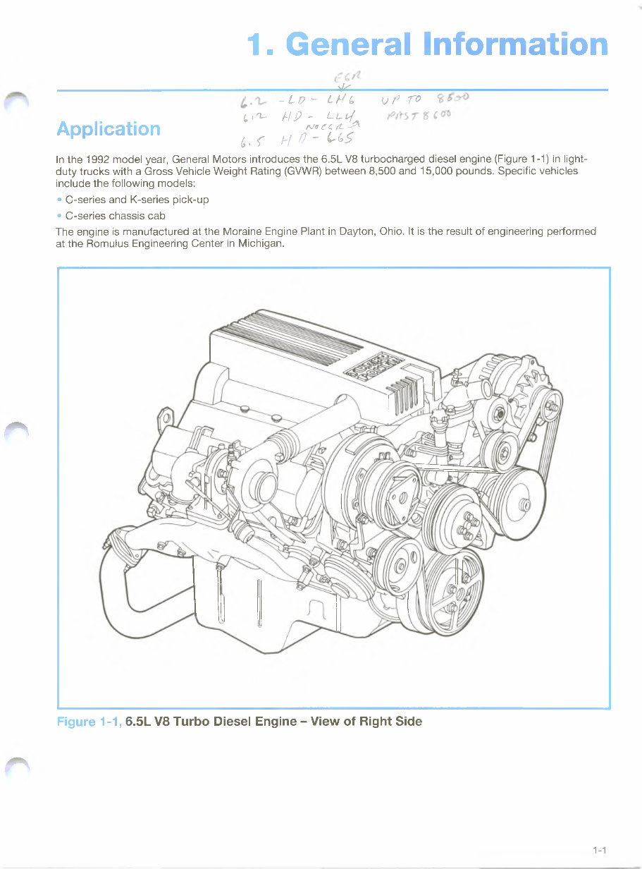
In the 1992 model year, General Motors introduces the 6.5L V8 turbocharged diesel engine (Figure 1-1) in light-
duty trucks with a Gross Vehicle Weight Rating (GVWR) between 8,500 and 15,000 pounds. Specific vehicles
include the following models:
• C-series and K-series pick-up
• C-series chassis cab
The engine is manufactured at the Moraine Engine Plant in Dayton, Ohio. It is the result of engineering performed
at the Romulus Engineering Center in Michigan.
rs
rs
Figure 1-1, 6.5L V8 Turbo Diesel Engine - View of Right Side
1-1
1. General Information
Identification
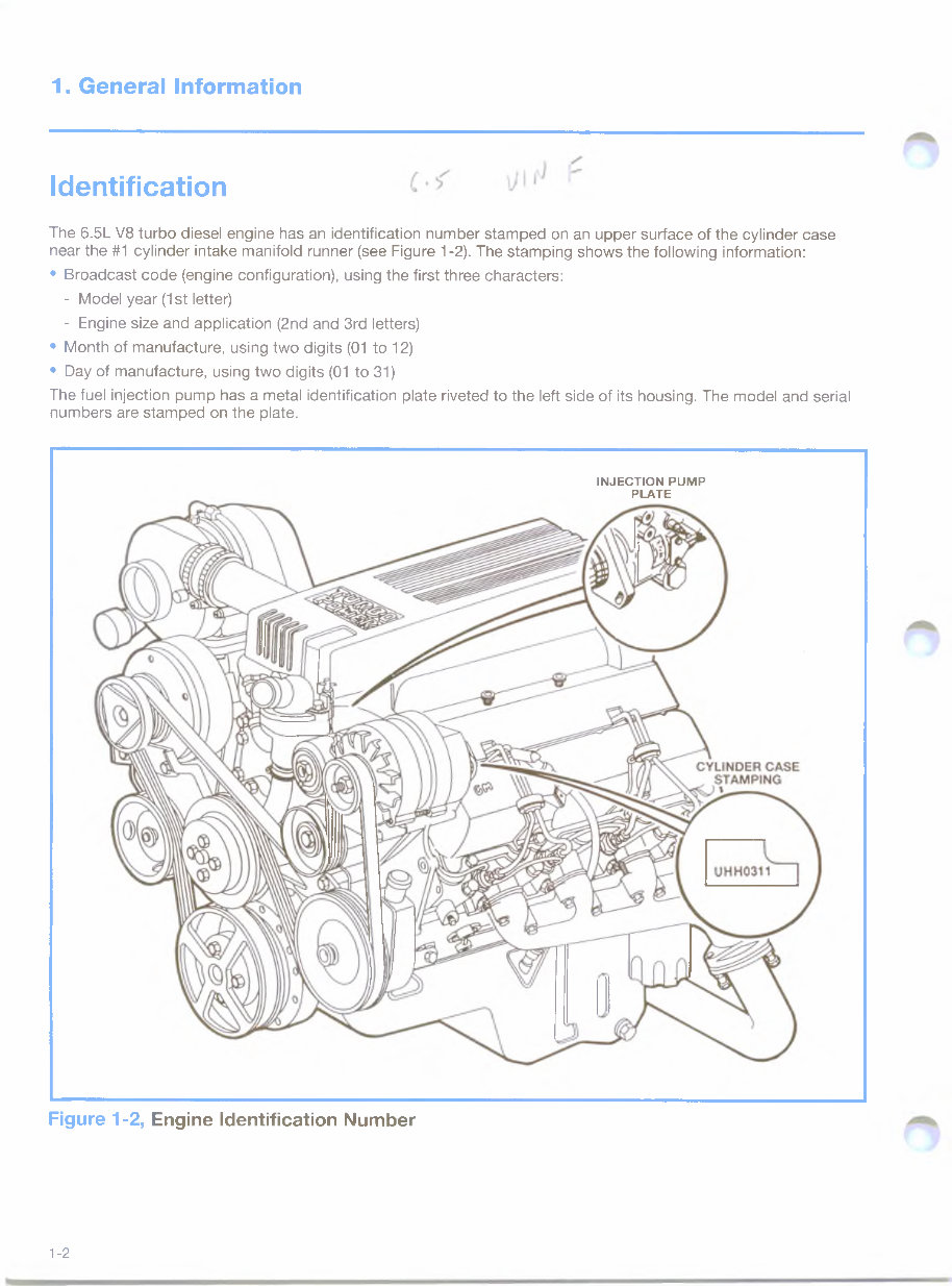
The 6.5L V8 turbo diesel engine has an identification number stamped on an upper surface of the cylinder case
near the #1 cylinder intake manifold runner (see Figure 1-2). The stamping shows the following information:
• Broadcast code (engine configuration), using the first three characters:
- Model year (1st letter)
- Engine size and application (2nd and 3rd letters)
• Month of manufacture, using two digits (01 to 12)
• Day of manufacture, using two digits (01 to 31)
The fuel injection pump has a metal identification plate riveted to the left side of its housing. The model and serial
numbers are stamped on the plate.
INJECTION PUMP
PLATE
Figure 1-2, Engine Identification Number
1-2
1. General Information
Design Features
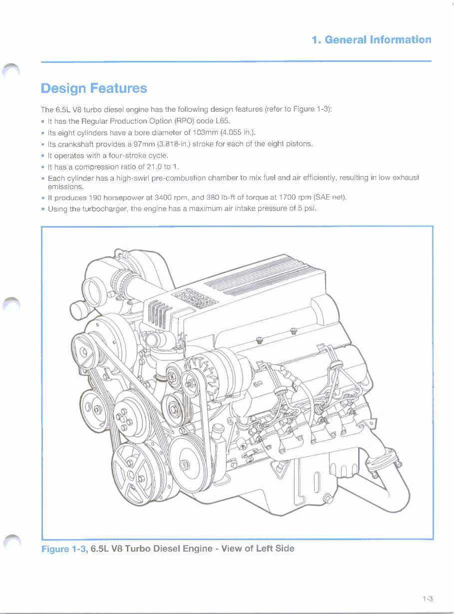
The 6.5L V8 turbo diesel engine has the following design features (refer to Figure 1-3):
• It has the Regular Production Option (RPO) code L65.
• Its eight cylinders have a bore diameter of 103mm (4.055 in.).
• Its crankshaft provides a 97mm (3.818-in.) stroke for each of the eight pistons.
• It operates with a four-stroke cycle.
• It has a compression ratio of 21.0 to 1.
• Each cylinder has a high-swirl pre-combustion chamber to mix fuel and air efficiently, resulting in low exhaust
emissions.
• It produces 190 horsepower at 3400 rpm, and 380 Ib-ft of torque at 1700 rpm (SAE net).
• Using the turbocharger, the engine has a maximum air intake pressure of 5 psi.
Figure 1-3, 6.5L V8 Turbo Diesel Engine - View of Left Side
1-3
1. General Information
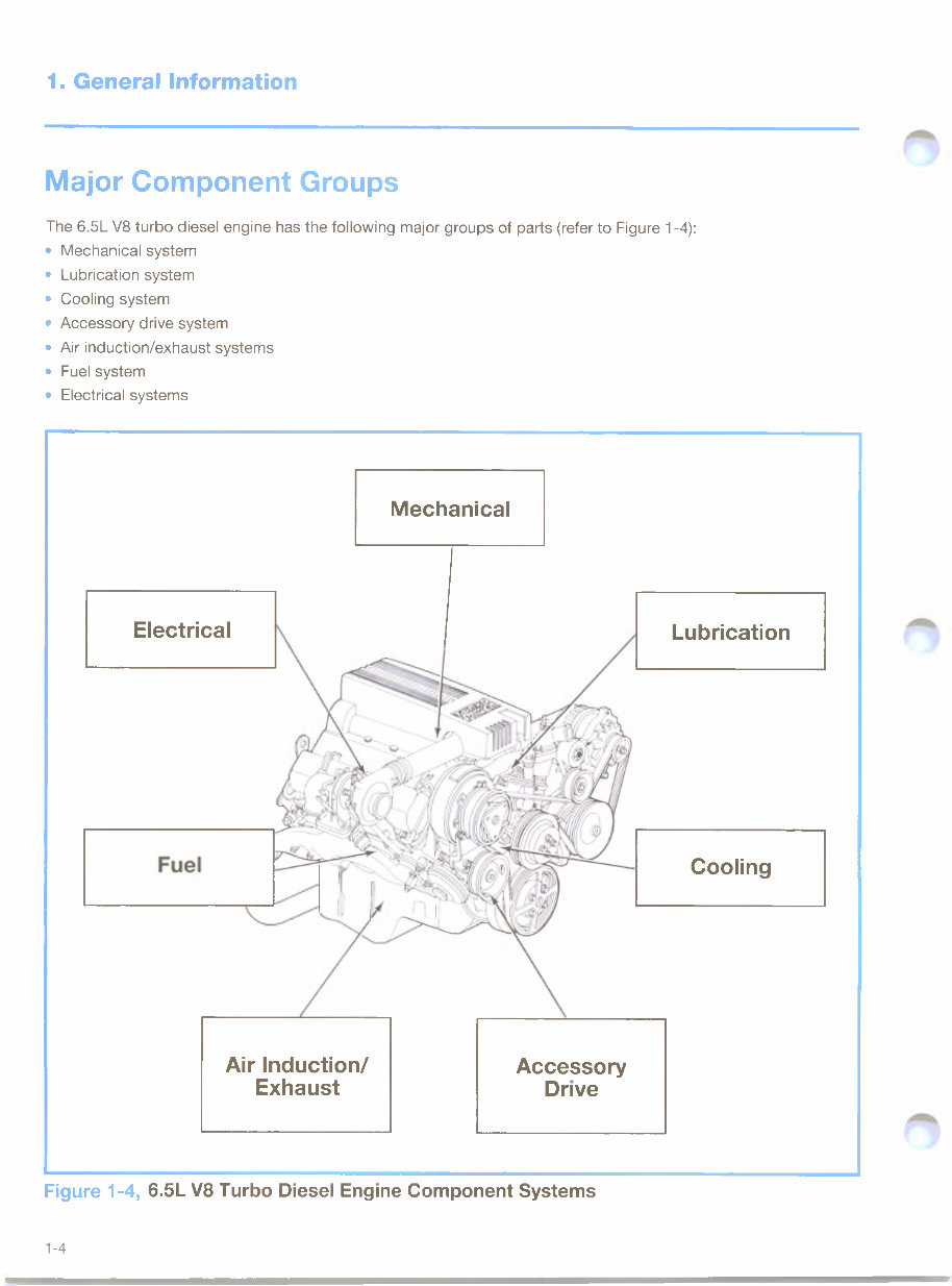
Major Component Groups
The 6.5L V8 turbo diesel engine has the following major groups of parts (refer to Figure 1-4):
• Mechanical system
• Lubrication system
• Cooling system
• Accessory drive system
• Air induction/exhaust systems
• Fuel system
• Electrical systems
Figure 1-4, 6.5L V8 Turbo Diesel Engine Component Systems
Electrical
Mechanical
Accessory
Drive
Cooling
Air Induction/
Exhaust
Lubrication
1-4
You're Reading a Preview
What's Included?
Fast Download Speeds
Offline Viewing
Access Contents & Bookmarks
Full Search Facility
Print one or all pages of your manual
$35.99
Viewed 76 Times Today


Secure transaction
What's Included?
Fast Download Speeds
Offline Viewing
Access Contents & Bookmarks
Full Search Facility
Print one or all pages of your manual
$35.99
General Motors STG 6.5L V8 Turbo Diesel Engine Student Workbook
*This manual is an introductory guide used in General Motors' training program and is not a repair manual.
Specific vehicles include the following models:
- C-series and K-series pick-up
- C-series chassis cab
While this booklet will serve as an excellent review of the extensive program presented in the training center session, it is not intended to substitute for the various service manuals normally used on the job.


