Generac GTH760/990,GTV760/990 OHVI V-Twin Engine Workshop Service Repair Manual
What's Included?
Lifetime Access
Fast Download Speeds
Online & Offline Access
Access PDF Contents & Bookmarks
Full Search Facility
Print one or all pages of your manual
FOREWORD This manual has been written and published by GENERAC ® POWER SYSTEMS, INC. to aid our dealers’ mechanics, company service person- nel and general consumers when servicing the products described herein. It is assumed that these personnel are familiar with the servicing procedures for these products, or like or similar products, manufac- tured and marketed by GENERAC ® POWER SYSTEMS, INC. It is also assumed that they have been trained in the recommended servicing procedures for these products, which includes the use of mechanics hand tools and any special tools that might be required. Proper service and repair is important to the safe, economical and reliable operation of the products described herein. The trouble- shooting, testing, service and repair procedures recommended by GENERAC ® POWER SYSTEMS, INC. and described in this manual are effective methods of performing such operations. Some of these operations or procedures may require the use of specialized equip- ment. Such equipment should be used when and as recommended. We could not possibly know of and advise the service trade of all conceivable procedures or methods by which a service might be per- formed, nor of any possible hazards and/or results of each procedure or method. We have not undertaken any such wide evaluation. There- fore, anyone who uses a procedure or method not recommended by the manufacturer must first satisfy himself that neither his safety, nor the product’s safety, will be endangered by the service or operating procedure selected. All information, illustrations and specifications contained in this manual are based on the latest product information available at the time of publication. However, GENERAC ® POWER SYSTEMS, INC. reserves the right to change, alter or otherwise improve the product at any time without prior notice. Some components or assemblies of the product described in this manual may not be considered repairable. Disassembly, repair and reassembly of such components may not be included in this manual. The engines described herein may be used to power a wide vari- ety of products. Service and repair instructions relating to any such products are not covered in this manual. For information pertaining to use of these engines with other products, refer to any owner’s or service manuals pertaining to said products.
RULES FOR SAFE OPERATION 4-CYCLE ENGINE THEORY SECTION 1: GENERAL INFORMATION SECTION 2: IGNITION SECTION 3: CARBURETION AND FUEL SYSTEM SECTION 4: GOVERNOR CONTROLS AND GOVERNOR SECTION 5: CYLINDER HEAD AND VALVES SECTION 6: ELECTRIC STARTER SECTION 7: ALTERNATORS SECTION 8: LUBRICATION SYSTEM SECTION 9: ENGINE DISASSEMBLY SECTION 10: CYLINDER AND CRANKCASE COVER SECTION 11: CRANKSHAFT AND CAMSHAFT SECTION 12: PISTON, RINGS AND CONNECTING ROD INSPECTION AND ASSEMBLY SECTION 13: ENGINE ASSEMBLY SECTION 14: SPECIFICATIONS TABLE OF CONTENTS A WORD ABOUT SPECIAL TOOLS Many of the procedures depicted in this manual require the use of special tools. Some of the tools required are available as Generac parts and are listed as such in this manual. ATTENTION! Generac Power Systems does not approve or authorize the use of these engines on All Terrain Vehicles (ATV’s), go-carts, motorbikes, aircraft products, personal watercraft, or vehicles intended for use in competitive events. The use of this product in any other than it’s intended application will void the warranty! Use of these engines in such applications could result in property damage, serious injury (including paralysis), or even death. 2 3 4 5 6 7 8 9 10 11 12 13 14 1
If you do not understand any portion of this manual, con- tact Generac or your nearest Generac Authorized Service Dealer for starting, operating and servicing procedures. Throughout this publication and on tags and decals affixed to the engine, DANGER, WARNING and CAUTION blocks are used to alert you to special instruction about a particular operation that may be hazardous if performed incorrectly or carelessly. Observe them carefully. These safety warnings cannot eliminate the hazards that they indicate. Strict compliance with the special instructions while performing the service plus “common sense” are major measures to prevent accidents. The following definitions apply to DANGER, WARNING, CAUTION and NOTE blocks found throughout the manual. These safety symbols indicate the following: * DANGER: After this heading you can read handling, installing, operating or servicing instructions that, if not strictly complied with, will result in personal injury. * WARNING: After this heading you can read han- dling, installing, operating or servicing instructions that, if not strictly complied with, may result in personal injury. * CAUTION: After this heading you can read instruc- tions for handling, installing, operating or servicing the engine that, if not strictly complied with, may result in damage to equipment and/or property. NOTE: After this heading you can read explanatory statements that require special emphasis. These symbols indicate the following: * Pointsoutimportantsafetyinformationthat,ifnot followed,couldendangerpersonalsafetyand/or propertyofyourselfandothers. Potential explosion hazard. Potential fire hazard. Potential electrical shock hazard. RULES FOR SAFE OPERATION Study these RULES FOR SAFE OPERATION carefully before operating or servicing this equipment. Become familiar with the OWNER’S MANUAL and with the engine. The engine can operate safely, efficiently and reliably only if it is properly operated and maintained. Many accidents are caused by fail- ing to follow simple and fundamental rules or precautions. Generac cannot possibly anticipate every possible circum- stance that might involve a hazard. The warnings in this manual and on tags and decals affixed to the equipment, are therefore, not all-inclusive. If you use a procedure, work method or operating technique Generac does not specifically recommend, you must satisfy yourself that it is safe for you and others. You must also make sure the procedure, work method or operating technique that you choose does not render the engine to be unsafe. * DANGER: Do not tamper with the engine governed speed. High operating speeds are dangerous and increase the risk of personal injury or damage to the equipment. Operating at low speeds with heavy load may shorten the engine’s life. BEFORE OPERATING • Gasoline is highly FLAMMABLE and its vapors are EXPLO- SIVE. Do not permit smoking, open flames, sparks or heat in the area while handling gasoline. Avoid spilling gasoline on a hot engine. Comply with all of the laws regulating storage and handling of gasoline. • Store gasoline and other fuels only in containers designed and approved for the storage of such materials. • Add gasoline in a clean, well-ventilated area. Wipe up any spilled gasoline immediately. If gasoline has been spilled, let it dry completely before starting the engine. • Do not overfill the fuel tank. Always allow room for fuel expansion. If the tank is overfilled, the fuel can overflow onto a hot engine and cause a FIRE or an EXPLOSION. • Allow at least two (2) feet of clearance on all sides of the engine, even while operating it outdoors, or you could damage the engine. • Thoroughly inspect the engine for loose or damaged parts before each use. Do not use the engine until adjustments or repairs are made. • Check the oil level in the engine before each use. • Inspect the engine periodically. Repair or replace all dam- aged or defective parts immediately. 2 RULES FOR SAFE OPERATION
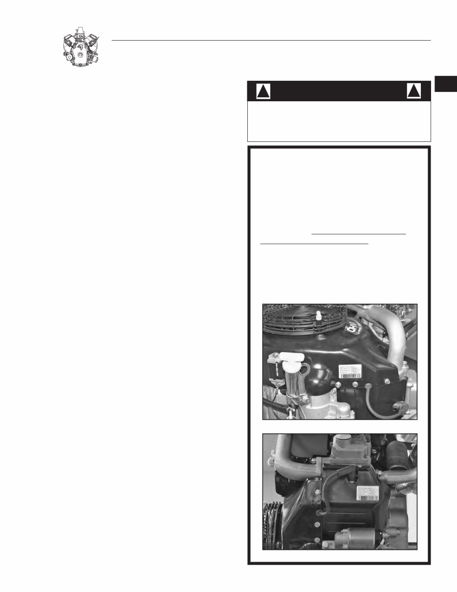
RULES FOR SAFE OPERATION • Inspect fuel system frequently for leaks or damage. Repair or replace any damaged or leaking component immediately. Never attempt to change, alter or modify the engine fuel system in any way that might affect safety or compliance with applicable codes and standards. WHILE OPERATING • This engine was designed and manufactured for specific applications. Do not attempt to modify the equipment or use it for any application for which it was not designed. • Generac Power Systems does not approve or authorize the use of these engines on All Terrain Vehicles (ATV’s), go- carts, motorbikes, aircraft products, personal watercraft, or vehicles intended for use in competitive events. The use of this product in any other than it’s intended application will void the warranty! Use of these engines in such applications could result in property damage, serious injury (including paralysis), or even death. • Engine exhaust gases contain DEADLY carbon monoxide gas. This dangerous gas, if breathed in sufficient concentrations, can cause unconsciousness or even death. Operate this equipment only in the open air where adequate ventilation is available. • Do not insert any object through the cooling slots of the engine. You could damage the equipment or injure yourself. • Do not operate the engine faster than the speed necessary to operate the equipment. Do not run the engine at high speed when not operating the equipment. • This engine requires an adequate flow of cooling air for its continued proper operation. Never operate the equipment inside any room or enclosure where the free flow of cooling air into and out of the equipment might be obstructed. With- out sufficient cooling air flow, the engine quickly overheats, damaging the engine or nearby property. • Do not smoke around the engine. Wipe up any fuel or oil spills immediately. Never leave oily or fuel soaked rags around the engine. Keep the area around the engine clean and free of debris. • Keep hands, feet, clothing, etc., away from moving parts of this engine. • Never operate the engine (a) in the rain; (b) in any enclosed compartment; (c) if the engine speed changes; (d) if the engine sparks; (e) if flame or smoke is observed while the engine is running. • Never work on this engine or handle any electrical device while standing in water, while barefoot, or while hands or feet are wet. DANGEROUS ELECTRIC SHOCK will result. SERVICE INFORMATION Serviceonthisenginewithinandafterthewarranty periodcanbeperformedbyanyauthorizedservice dealer.Servicetechniciansarefactorytrainedand capableofhandlingallserviceneeds. Whencontactinganauthorizedservicedealerabout partsandservice, always supply the complete model number and serial number ofyourunitas givenonitsdataplatedecal.Seetheillustration belowforthelocationofthedecal. Thewarrantyforthisengineisincludedintheown- er’smanual. The engine exhaust from this product contains chemicals known to the State of California to cause cancer, birth defects, or other repro- ductive harm. WARNING: ! !
4-CYCLE ENGINE THEORY (A) INTAKE The piston is travelling from top dead center (TDC) to bottom dead center (BDC). The cam has opened the intake valve. The piston's downward movement in the cylinder creates a partial vacuum in the cylinder. Air at atmospheric pressure is drawn into the cylinder through the carburetor and is mixed with fuel in the carburetor. The fuel-air mixture flows through the open intake valve into the cylinder. When the piston reaches BDC, the intake stroke is over. (B) COMPRESSION As the piston reaches bottom dead center (BDC), both the intake and exhaust valves are closed. The piston moves upward toward TDC and the fuel-air mixture is compressed. Just before the piston reaches TDC, ignition occurs. (C) IGNITION AND POWER By the time the piston reaches TDC , combustion is already in progress. The intake and exhaust valves remain closed as the expanding gases of combustion force the piston downward. (D) EXHAUST The exhaust stroke begins when the piston has reached BDC and has started its upward movement. The intake valve is closed. The exhaust valve is open to let gases escape. If the engine is to run properly, four () events must occur in the proper sequence and at the correct time. These events are (A) intake, (B) compression, (C) ignition and power, and (D) exhaust.
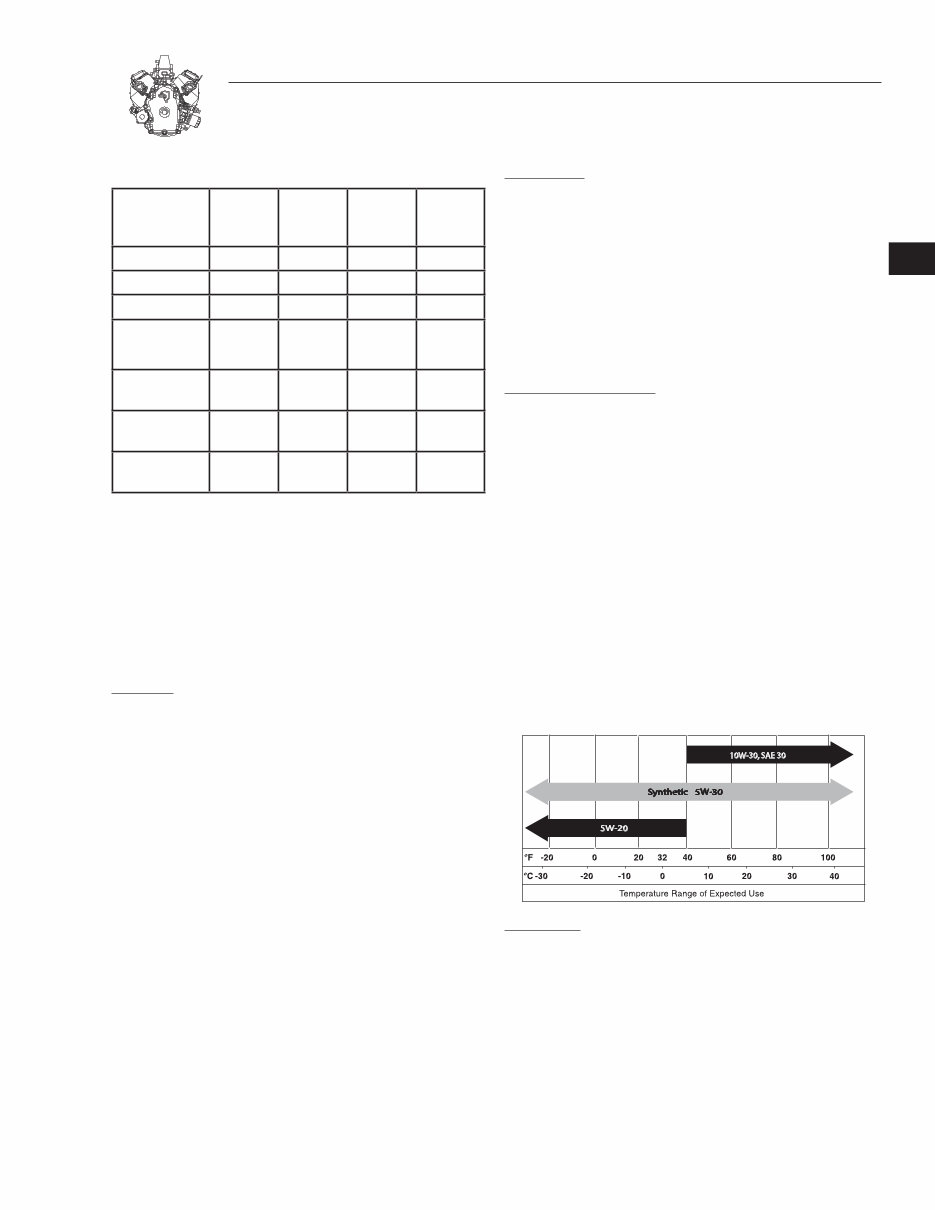
- SECTION 1: GENERAL INFORMATION MAINTENANCE SCHEDULE Every 8Hoursor Daily Every 25Hours Season Every 50Hours Season Every 100Hours Season CheckOilLevel • ChangeOil Note1 ChangeOilFilter Note1 ServiceAirFilter Foam Pre-Filter if equipped Filter (Note2) ReplaceorClean SparkPlug • CleanSpark ArrestorScreen • ValveClearance Note3 NOTE 1:Changeoilandfilterafterfirst8hoursofoperationandthen every100hoursthereafter.Changesoonerwhenoperatingunderaheavy loadorinadustyordirtyenvironmentorinhighambienttemperature. NOTE 2: Cleanmoreoftenwhenoperatingindirtyordustyconditions. Replacecanisterstylefilterevery500hours. NOTE 3:Checkvalvelashandadjustifnecessaryafterfirst50hoursof operationandevery100hoursthereafter. FUEL AND OIL RECOMMENDATIONS GASOLINE: We recommend the use of clean, fresh lead-free gasoline. A minimum of 85 octane is recommended. The use of lead- free gasoline results in fewer combustion deposits and longer valve life. NOTE: Using a fuel additive such as STA-BIL® fuel stabi- lizer, or an equivalent, will prevent gum deposits from forming in the engine’s fuel system. NOTE: Some fuels, called oxygenated or reformulated gasolines, are gasolines blended with alcohols or ethers. Excessive amounts of these blends can damage the fuel system or cause performance problems. Do not use gasoline which contains Methanol. If any undesirable operating symptoms occur, use gasoline with a lower percentage of alcohol or ether. It is also recommended that gasoline be purchased in small quantities, not more than a 0 day supply. FRESH gasoline minimizes gum deposits, and also will ensure fuel volatility tailored for the season in which the engine will be operated. LUBRICATION: Oil has four purposes. It cools, cleans, seals and lubricates. During normal operation, small particles of metal from the cylinder walls, pistons, bearings and combustion deposits will gradually contaminate the oil. Dust particles from the air also contaminate the oil forming an abrasive mixture which can cause wear to all of the internal moving parts of the engine, if the oil is not changed regularly. Fresh oil also assists in cooling. Old oil gradually becomes thick and loses its cooling ability as well as its lubricating qualities. RECOMMENDED OIL TYPE: Using the proper type and weight of oil in the crankcase is extremely important. Check the oil before each use and change the oil regularly (see Figures - through -5). Failure to use the correct oil, or using dirty oil, can cause premature engine wear and failure. Use only high quality detergent oil rated with an API service classification SJ or higher (example: SL or SM). Do NOT use oil designated "for diesel engines only" (example: CD). The recommended oil weights include the following: • During summer months: SAE 0. An acceptable substi- tute is SAE 0W-0. After first oil change, synthetic oil is acceptable. • During winter months: SAE 5W-0 or synthetic 5W-0. DO NOT USE SAE 0W-0. After first oil change, synthetic oil is acceptable. CHANGE OIL: See "Section : Specifications" for crankcase oil capacities. Use no special additives. Make sure that the unit is level when filling with oil. DO NOT OVERFILL. IMPORTANT: DO NOT OVERFILL. Check and maintain oil level regularly. Change oil and filter after first eight (8) hours of operation. Thereafter, change oil and filter every 00 hours of opera- tion. Change oil more often if engine is operated in dirty or dusty conditions or if engine is operated under heavy loads or in high ambient air temperatures. 1
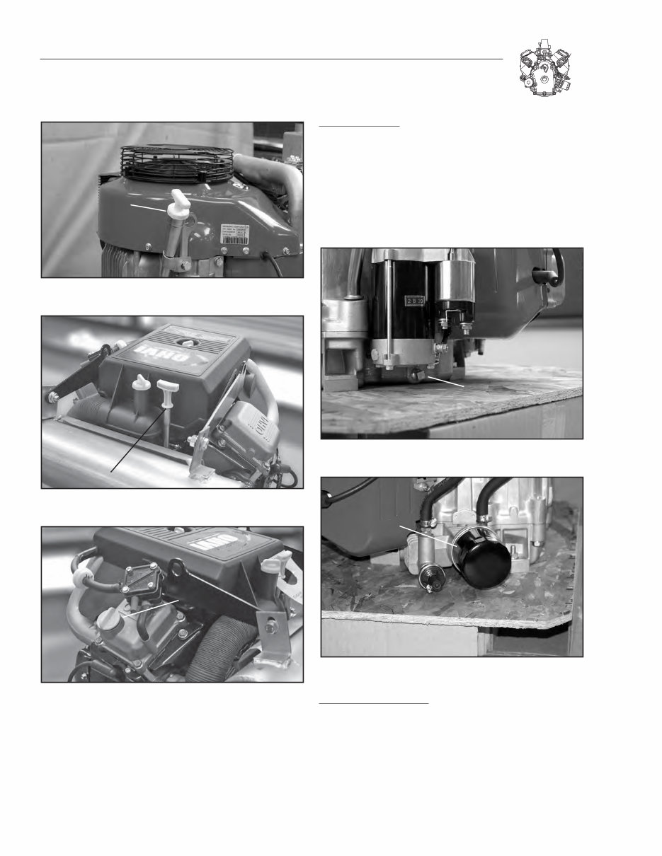
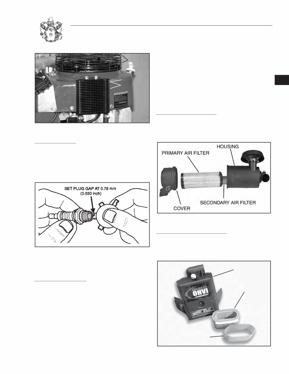
-2 SECTION 1: GENERAL INFORMATION FILL / CHECK Figure 1-1. Oil Fill/Check Vertical Engine OIL CHECK Figure 1-2. Oil Check Horizontal Engine OIL FILL Figure 1-3. Oil Fill Horizontal Engine Remove oil drain plug and drain oil while engine is still warm, Figure -. Change oil filter (Figure -5) and replace drain plug. Remove dipstick and refill slowly with new oil of proper service classification and viscosity grade. Refill to full mark on dipstick. When checking oil level, dipstick must be all the way in for accurate readings. CHANGE OIL FILTER: Replace oil filter every 00 hours. Before installing new filter, lightly oil filter gasket with fresh clean engine oil. Screw filter on by hand until gasket contacts filter adapter. Tighten / to one full turn farther, Figure -5. Start and run engine at idle for 0 seconds and stop engine. Recheck oil level and add if required. Restart engine and check for oil leaks. DRAIN Figure 1-4. Oil Drain FILTER Figure 1-5. Oil Filter CLEANING INTAKE SCREEN: Grass particles, chaff or dirt can clog the air cooling system, especially after prolonged service in cutting dry grass or when operating in extremely dusty or dirty conditions. Continued operation with a clogged cooling system can cause severe over- heating and possible engine damage. Figure -6 shows the areas to be cleaned. This should be a regular maintenance operation, or clean intake screen and oil cooler fins after each use.
- SECTION 1: GENERAL INFORMATION INTAKE SCREEN OIL COOLER FINS Figure 1-6. Clean Intake Screen & Oil Cooler Fins REPLACE SPARK PLUGS: Replace spark plugs every 00 hours of operation or every season, whichever occurs first. Replace spark plugs if electrodes are burned away, or the porcelain is cracked. Set spark plug gap at .76 mm (.00") for all models. Torque spark plugs to 9.0 Nm (68 in. lbs.). Figure 1-7. Setting Spark Plug Gap Note: For proper spark plug replacement, refer to the owner’s manual for the specific product. AIR CLEANER MAINTENANCE: * WARNING: NEVER OPERATE ENGINE WITH AIR CLEANER ASSEMBLY OR AIR CLEANER CARTRIDGE REMOVED. FIRE MAY RESULT. A properly serviced air cleaner protects internal parts of the engine from dirt and dust particles in the air. If air cleaner instructions are not carefully followed, dirt and dust which should be collected in the cleaner will be drawn into the engine. These particles are highly abrasive and will cause the piston rings and cylinder bore to wear quickly. As the rings and cylinder bore become worn, these abrasive particles enter the crankcase and contaminate the oil, forming an abrasive mixture which will cause wear on all of the internal moving parts. The air cleaner on every engine brought in for a check up or repair should be examined and serviced. If the air cleaner shows signs of neglect, show it to the customer before clean- ing. Instruct the customer on proper care, to assure long engine life. Note: Replace air cleaner gaskets and mounting gaskets that are worn or damaged, to prevent dirt and dust from entering engine due to improper sealing. Replace bent air cleaner mounting bracket if necessary. SERVICE CANISTER AIR CLEANERS: Clean the air filter element(s) with compressed air every 50 hours or every season, whichever occurs first. Replace the air filter element(s) every 500 hours or if damaged (see Figure -8). Figure 1-8. Canister Air Cleaner Components SERVICE DUAL ELEMENT AIR CLEANERS: Remove and service foam pre-cleaner every 25 hours or every season, whichever occurs first. Service cartridge every 50 hours or every season, whichever occurs first (see Figure -9). AIR FILTER ELEM FOAM PRE-CLEANER COVER Figure 1-9. Dual Element Air Cleaner Components 1
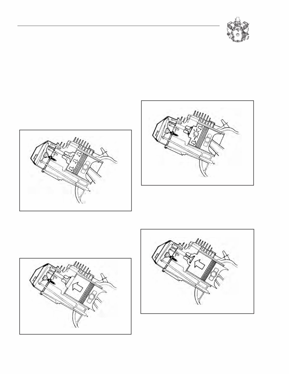
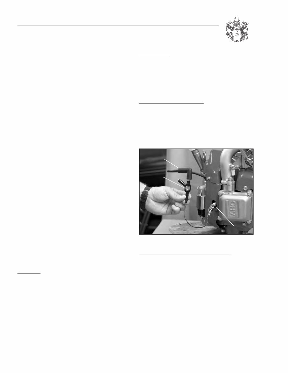
- SECTION 1: GENERAL INFORMATION Note: The air cleaner assemblies on some equipment may have been supplied by the equipment manufacturer. See the equipment manufacturer’s owner’s manual for service information specific to that product. TROUBLESHOOTING Most complaints concerning engine operation can be clas- sified as one or a combination of the following: . Will not start 2. Hard starting . Lack of power . Runs rough 5. Vibration 6. Overheating 7. High oil consumption Note: What appears to be an engine malfunction may be a fault of the powered equipment rather than the engine. If equipment is suspect, see equipment affecting engine operation. SYSTEMATIC CHECK If the engine will not start and the cause of malfunction is not readily apparent, perform a systematic check in the fol- lowing order: . Fuel 2. Ignition . Compression This check-up, performed in a systematic manner, can usually be done in a matter of minutes. It is the quickest and surest method of determining the cause of failure. The basic checkup procedure is the same for all engine models, while any varia- tion, by model, will be shown under the subject heading. CHECK FUEL: The fuel pressure can be checked using a pressure tester kit for LP and NG systems. Also check the following: . Are the tanks full? 2. Is the fuel stale? . Is the tank vent open? . Is the fuel shutoff valve open? 5. Is the fuel pump working? 6. Is the fuel solenoid working? CHECK IGNITION: If spark does not occur look for: • Shorted ignition/ground wire (see Page 2-) • Two closed diodes in ground wire harness (see Page 2-) • Incorrect ignition coil air gap (see Page 2-) • Ignition coil failure CHECK IGNITION (ENGINE RUNNING): If engine runs but misses during operation, a quick check to determine if ignition is or is not at fault can be made by installing a spark tester (Generac P/N 0C5969) between the spark plug lead and each spark plug, Figure -0. A spark miss will be readily apparent when the engine is running. If spark is good but engine misses, check for a fouled spark plug. TESTER SPARK PLUG LEAD SPARK PLUG Figure 1-10. Running Check CHECK IGNITION (FOULED PLUG OR OTHER CAUSES): To check for a fouled spark plug or a non-functioning cyl- inder, attach the spark tester (Generac P/N 0C5969) between the spark plug lead and each spark plug. Start and run engine at top no load speed. Now ground one spark plug, Figure - . The engine should continue to run on the other cylinder. Repeat this test with the other cylinder. If the engine will not continue to run when making this test, the cylinder that is NOT grounded is not functioning and/or the spark plug is fouled. Install a new spark plug before proceeding. If miss continues, problem may be carburetion or compression. See Check Fuel, Check Compression, and Cylinder Balance Test.
This workshop service repair manual is for the Generac GTH760/990, GTV760/990 OHVI V-Twin Engine. It contains high-quality diagrams and instructions for servicing and repairing your Generac. This manual is essential for both professional mechanics and DIY enthusiasts, helping you save on service repair and maintenance costs.
Rules for Safe Operation
4-cycle engine theory
Section 1: general Information
Section 2: Ignition
Section 3: Carburetion and Fuel System
Section 4: Governor Controls and Governor
Section 5: Cylinder Head and Valves
Section 6: electric starter
Section 7: Alternators
Section 8: Lubrication System
Section 9: Engine Disassembly
Section 10: Cylinder and Crankcase Cover
Section 11: Crankshaft and Camshaft
Section 12: Piston, Rings and Connecting Rod Inspection and Assembly
Section 13: Engine Assembly
Section 14: Specifications
This service repair manual is available for instant download, eliminating shipping costs and waiting time. It is compatible with all versions of Windows & Mac, as well as APP ISO, iPhone, iPod, Android, etc. The language is English, and it requires Adobe Reader. All pages are printable, making it a valuable resource for your Generac.
Don't wait any longer! Get your manual now and enhance your understanding of your Generac.
Recently Viewed
5,521,897Happy Clients
2,594,462eManuals
1,120,453Trusted Sellers
15Years in Business
Price:
Actual Price:
Generac GTH760/990,GTV760/990 OHVI V-Twin Engine Workshop Service Repair Manual