TABLE OF CONTENTS - 2 - 1. GENERAL INFORMATION, HANDLING 5 1.3 ORGANISATION AND USE OF THIS REPAIR MANUAL ............................................................................. 5 1.4 SERVICE ................................................................................................................................................. 5 1.5 AFTER SALES - SERVICE: FALKE - SPARE PARTS PROGRAM .............................................................. 5 1.6 ENGINE, MODEL AND TYPE DESIGNATION ........................................................................................... 6 1.7 SAFETY INSTRUCTIONS.......................................................................................................................... 7 2. TECHNICAL DATA 9 2.1 CONSTRUCTION DATA, CONSUMPTIONS AND PRESSURES .................................................................. 10 2.1 CONSTRUCTION DATA, CONSUMPTIONS AND PRESSURES .................................................................. 11 2.2 OUTPUT, TORQUE, CONSUMPTION ...................................................................................................... 12 2.2 OUTPUT, TORQUE, CONSUMPTION ...................................................................................................... 13 2.3 SCREWS - TIGHTENING TORQUES, SEALING AND ADHESIVE MATERIALS.......................................... 15 2.4 TOOLS .................................................................................................................................................. 16 2.5 TECHNICAL DESCRIPTION ................................................................................................................... 19 2.6 APPLICATIONS ..................................................................................................................................... 19 3. DISMANTLING AND ASSEMBLY PROCEDURES ON THE BASIC ENGINE 20 3.1 BASIC REQUIREMENTS ........................................................................................................................ 20 3.2 DISMANTLING PROCEDURES ...................................................................................................... 21 4. MEASUREMENT TABLE- WEARING PARTS 32 4.1 CRANKCASE ..................................................................................................................................... 32 4.2 CRANKSHAFT .................................................................................................................................. 33 4.3 CAMSHAFT ....................................................................................................................................... 34 4.4 GEAR COVER.................................................................................................................................... 35 4.5 SHAFTS, BEARINGS ........................................................................................................................ 36 4.6 CONNECTING ROD.......................................................................................................................... 37 4.7 CYLINDER LINER ............................................................................................................................ 38 4.8 PISTON 15/18W ................................................................................................................................. 39 4.9 PISTON 32W ...................................................................................................................................... 40 4.10 CYLINDER HEAD 15/18W........................................................................................................... 41 4.11 CYLINDER HEAD 32W................................................................................................................ 42 5. ENGINE REASSEMBLY 43 6. TEST RUN, ADJUSTMENTS, CHECKS 56 7. ELECTRICAL SYSTEM 66 7.1 FLYWHEEL – DYNAMO / REGULATOR ................................................................................................. 66 7.2 FUNCTION TESTS: ................................................................................................................................ 66 7.3 HAZARDS / CAUSES OF FAILURE ......................................................................................................... 67 7.4 12 V FLYWHEEL – DYNAMO / REGULATOR, GRAPHS........................................................................ 68 7.5 WIRING DIAGRAMS ........................................................................................................................ 69 7.5.1 DIAGRAM 1 ................................................................................................................................. 69 7.5.2 DIAGRAM 2 .............................................................................................................................. 71 7.5.3 DIAGRAM 3 .............................................................................................................................. 72 7.5.4 DIAGRAM 4 .............................................................................................................................. 73 7.5.5 DIAGRAM 5 .............................................................................................................................. 74 8. TROUBLESHOOTING 75 8.1 ENGINE WILL NOT START..................................................................................................................... 75 Downloaded from www.Manualslib.com manuals search engine
TABLE OF CONTENTS - 3 - 8.2 ENGINE STARTS BUT FIRES INTERMITTENTLY OR DIES ........................................................................ 76 8.3 POOR ENGINE PERFORMANCE AND / OR BLACK SMOKE....................................................................... 76 8.4 POOR ENGINE PERFORMANCE AND/OR BLACK SMOKE ........................................................................ 77 8.5 IMPERFECT OPERATING BEHAVIOUR ................................................................................................... 77 Downloaded from www.Manualslib.com manuals search engine
PREFACE - 4 - We congratulate you on your choice of a FARYMANN engine and wish you much pleasure with this German quality product. These operating instructions are based on the latest state of technical development. In preparing them, every effort has been made to avoid errors. However, we accept no liabil- ity for any errors of presentation or description, nor for any omissions. Modifications may also occur because of ongoing technical developments. We reserve the right to make modifications without giving prior notice. Everyone responsible for the installation, commissioning, operation, maintenance or repair of the engines must read and follow the operating instructions and particularly the "Safety" chapter. The engine is built according to the state-of-the-art, and in compliance with recognised safety regulations. Nevertheless, while the engine is in use, there may be physical or mortal dangers to the user or to third parties, and also damage to the engine and to other property. For these reasons, the engine must only be used when it is in perfect technical condition, and when those involved are aware of the dangers and the safety precautions. In particular, malfunctions which could impair safety must be rectified immediately. The engine must only be used as intended. FARYMANN DIESEL GmbH is not responsible for damage resulting from incorrect use. Such risk is borne solely by the user. Correct use also includes following the operating instructions and adhering to the operat- ing, servicing and maintenance conditions. The engine must only be operated and serv- iced by reliable, trained personnel in compliance with the relevant accident prevention regulations as well as other generally-recognised rules of safety and occupational health. FARYMANN DIESEL GmbH accepts no liability for any damage resulting from unauthor- ised conversions or modifications to the engine. Replacement parts must meet the techni- cal requirements specified by FARYMANN DIESEL GmbH. This is always guaranteed if original replacement parts are used. Fitting and/or using parts and accessories not sup- plied by FARYMANN DIESEL GmbH may have a detrimental effect on your engine under certain circumstances. FARYMANN DIESEL GmbH accepts no liability whatsoever for any damage resulting from the use of non-original replacement parts or accessories. Downloaded from www.Manualslib.com manuals search engine
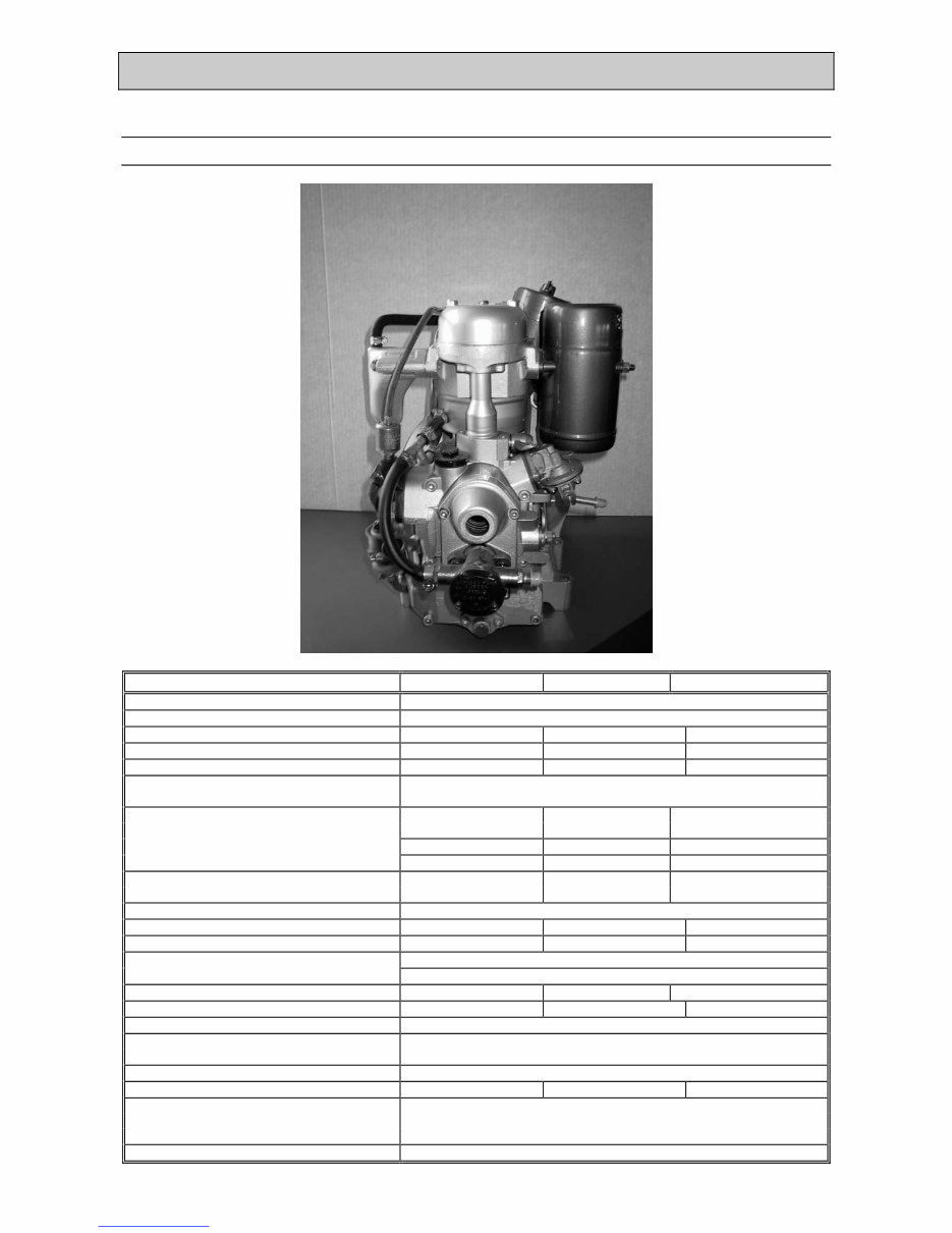
GENERAL INFORMATION - 5 - 1. General Information, Handling FARYMANN DIESEL engines type 15/18/32W are 4 stroke, direct injection diesel engines. They are built as single cylinder engines vertical cylinder configuration. The direct injection guarantees an outstanding level of efficiency, with low fuel consumption and excellent cold starting behaviour. Bosch fuel injection equipment is used on all engines. A high-precision centrifugal governor ensures accurate speed (RPMs) and load control. Special modified water-cooled Farymann engines fulfill BSO I/II and EPA – requirements. 1.3 Organisation and Use of this Repair Manual The descriptions, data and illustrations refer to those assembly and adjustment procedures where FARYMANN engines differ from ordinary diesel engines. − It is assumed that all work on the engine will be carried out by competent staff who have received training. − Special tools must be available, as described in the manual, together with good-quality standard tools. 1.4 Service − If you have any further questions about the Repair Manual, we recommend you to contact your nearest FARYMANN Service Centre. − Circular letters and training courses ensure that our service personnel have an answer to every question. Please ask for a list of all our service locations from your own FARYMANN Service Centre. 1.5 After Sales - Service: FALKE - Spare Parts Program "Service, Quality and Progress" is our motto. This is why we have developed our very own computer-aided "FALKE" Service System. The FALKE System makes it possible for FARYMANN’s world-wide network of distributors to satisfy all spare parts and service requirements quickly and reliably, ensuring that we maintain a close relationship with our customers. Downloaded from www.Manualslib.com manuals search engine
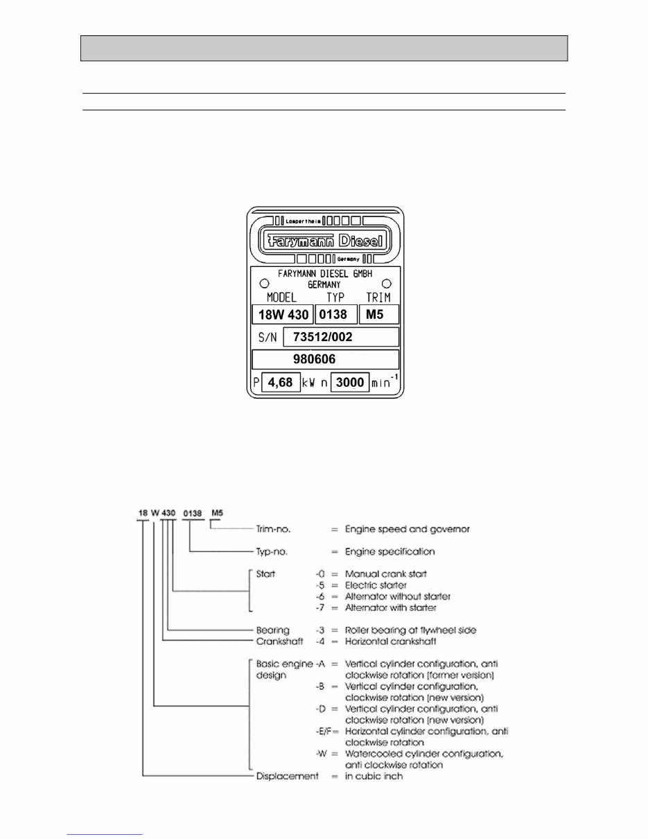
GENERAL INFORMATION - 6 - 1.6 Engine, Model and Type Designation Every engine can be unmistakably identified using the manufacturer’s nameplate. As well as the clearly defined 12-digit code number, this refers to the order number (SN) and the date of construction. This information must always be provided when making any enquiries or complaints, etc. As of July 1985, the consecutive engine number is also imprinted on the crankcase. As of July 1982, the type designation (a 12-digit code number) is used in addition to the series number (SN = Order Number). (See manufacturer’s nameplate). e.g. 18W430.0138 M5 98 06 06 Date of Production Downloaded from www.Manualslib.com manuals search engine
GENERAL INFORMATION - 7 - 1.7 Safety Instructions Only use transport devices specified by the manufacturer, and only follow hoisting instructions specified by the manufacturer. When handling fuels, lubricants and other chemical substances, follow the safety regulations which apply to the product. Do not smoke when handling inflammable fuels or lubricants. Vapours from lubricating oil or fuel may catch fire if they come into contact with sources of ignition. Be careful when handling hot or corrosive fuels, lubricants or other sub- stances (risk of burning or scalding). Never carry out maintenance and repair work when the engine is running. Ensure that the engine cannot start unintentionally. Before turning the engine over, make sure that nobody is in the danger area. When you have finished working on the engine, always check that the safety devices have been refitted, and that all tools have been removed from the engine. Never carry out any work on safety valves (e.g. modification of the spring tension). Defective safety valves must be replaced with new ones. When disposing of used fuels, lubricants and filters, follow the regulations which apply locally. Before or when you start the engine, check: − all lines, hoses and screwed connections for leaks; − safety devices for completeness and ability to operate. When starting the engine by hand, only use the starting device specified by the manufacturer (starting handle with kick back limiter, recoil starting) and follow the handling instructions. Never use cold starting aids based on ethyl oxide. Because of the explosion hazard, it is forbidden to start up a compressed- air start engine with combustible gases (fuel gases) or oxygen, even in an emergency. Downloaded from www.Manualslib.com manuals search engine
GENERAL INFORMATION - 8 - 1.5 Safety Instructions Only operate IC engines in enclosed areas if there is adequate ventilation. Before you start the engine in an enclosed environment, make sure that there is sufficient ventilation. Ensure that the engine only slows down to full stop after 10 - 20 seconds! If there are any safety devices on the engine, or on the machine into which the engine is built, they must be refitted when the maintenance and repair work has been finished. Before starting any work on the electrical components, the power supply to all live parts must be cut off. Only carry out maintenance and repair work when the engine parts are in a stable position. Liquids ejected under high pressure (such as fuels or oils) may penetrate the skin and cause severe injuries. To carry out cleaning work on the engine, always use a non-combustible detergent, or one which has a flash point of more than 65 °C. CALIFORNIA Proposition 65 Warning Diesel engine exhaust and some of its constituents are known to the State of California to cause cancer, birth de- fects, and other reproductive harm. Downloaded from www.Manualslib.com manuals search engine
TECHNICAL DATA - 9 - 2. Technical Data Engine Type 15W 18W 32W Design verticall Number of Cylinders 1 Bore 75 mm 82 mm 95 mm Stroke 55 mm 55 mm 74 mm Cubic capacity (piston displacement) 242 cm3 290 cm3 524 cm3 Direction of rotation (looking at power take- off side) anti clockwise Max. power / 3000 RPM F (DIN 70020) 4,76 kW 5,70 kW 9,74 kW IFN-ISO (DIN 6271) 4,33 kW 5,20 kW 8,85 kW ICFN-ISO (DIN 6271) 3,90 kW 4,70 kW 8,00 kW Max. torque 14,4 Nm 16,7 Nm 30,2 Nm (DIN 70020) at 2400 RPM at 2400 RPM at 2400 RPM Max. speed 3600 RPM Mean piston speed at 3000 RPM 5,5 m/s 5,5 m/s 7,4 m/s Compression ratio 1 : 20 1 : 19,1 – 22,6 1 : 20 Valve clearance, exhaust valve 0,2 mm intake valve 0,2 mm Tank capacity --- --- --- Lubricating oil volume (sump capacity) 1,0 l 1,0 l 1,6 l Lubricating oil consumption 1,0 g/kWh Starter motor rated voltage 12 V Battery capacity required 55Ah Weight 37 kg 37 kg 75 kg Cooling water requirement 7 – 8 l/min Permissible tilt during operation : Longitudinal 15 ° Lateral 15 ° Downloaded from www.Manualslib.com manuals search engine
TECHNICAL DATA - 10 - 2.1 Construction Data, Consumptions and Pressures Technical Data Table 1 Engine Type 15W 18W 32W Construction data dimen- sion System * four stroke Combustion Proce- dure * direct injection Cooling System * Water-cooled Design / Configuration * 1-cylinder / vertical Bore (mm) 75 82 95 Stroke (mm) 55 55 74 Displacement (cm 3 ) 242 290 524 Compression Ratio * 1 : 20,0 1 : 19.1 - 1 : 22,6 1 : 20,0 Temperatures dimen- sion Permissible air intake temperature (max.) (°C) 50 Permissible exhaust gas temperature (max) (°C) 580 Permissible cooling air temperature (max.) (°C) 50 Permissible fuel temperature (max.) (°C) 80 Permissible lub. oil temperature (max.) (°C) 130 Consumptions (at IFN Output) Specific fuel con- sumption, 3000 RPM (g/kWh) 305 300 255 Fuel tank content (l) NO Feed pump (max. lift) (mm) 300 Fuel * to DIN 51 601 / ASTM D 975-77 + 2D/BS 28669 1970 A1 + A2 Specific lub. oil con- sumption (g/kWh) 1 max. lub. oil capacity (g/l) 1100 / 1,25 1100 / 1,25 1380 / 1,56 Topping up volume lower-upper mark t /b tt k (g/l) 200 / 0,226 200 / 0,226 240 / 0,270 Lub. Oil quality * HD oil: minimum quality CC; better, CD quality (API-spec.) and multigrade oils Pressures Injector setting (bar) 200 200 175 Oil pressure (max.) (bar) 5 Permissible air intake vacuum (kPa) 2 Permissible exhaust gas back pressure (kPa) 5 Downloaded from www.Manualslib.com manuals search engine
Thank you for considering this comprehensive Service Repair Workshop Manual.
DESCRIPTION:
This manual provides detailed Service & Repair Procedures, enabling you to save a significant amount of money by performing your own repairs. It offers easy-to-follow, step-by-step instructions and illustrations covering all aspects of servicing and repairs. Once downloaded, the manual is yours to keep forever. You have the option to print individual pages, chapters, or the entire manual, and it can also be saved to your tablet.
MODELS COVERED:
All Models/Engines/Trim/Transmissions Types Are Covered.
CONTENTS:
This high-quality Service Repair Workshop Manual covers all repair procedures A-Z.
Every repair and service procedure is covered.
COMPUTER REQUIREMENTS:
This downloadable Manual is compatible with All PC & MAC Computers, tablets, and mobile phones. The only software required is Adobe Reader, which can be downloaded for free.
INSTANT DELIVERY:
This manual will be instantly emailed to the email address used during checkout after receiving payment by Visa, MasterCard, or PayPal.