


9 Gerade
2
9
Engine Description
2.1 Model
2.2 Engine Illustration
2.3 Lube Oil Circuit Schematic
2.4 Fuel System Schematic
7343en_k02_pdf 05.10.1999, 9:20 Uhr 9
10
2
26 332 2
26 421 1 26 422 0
*
0 0 0 2 2 1 3 5
*
C
23045678
D
Engine Description
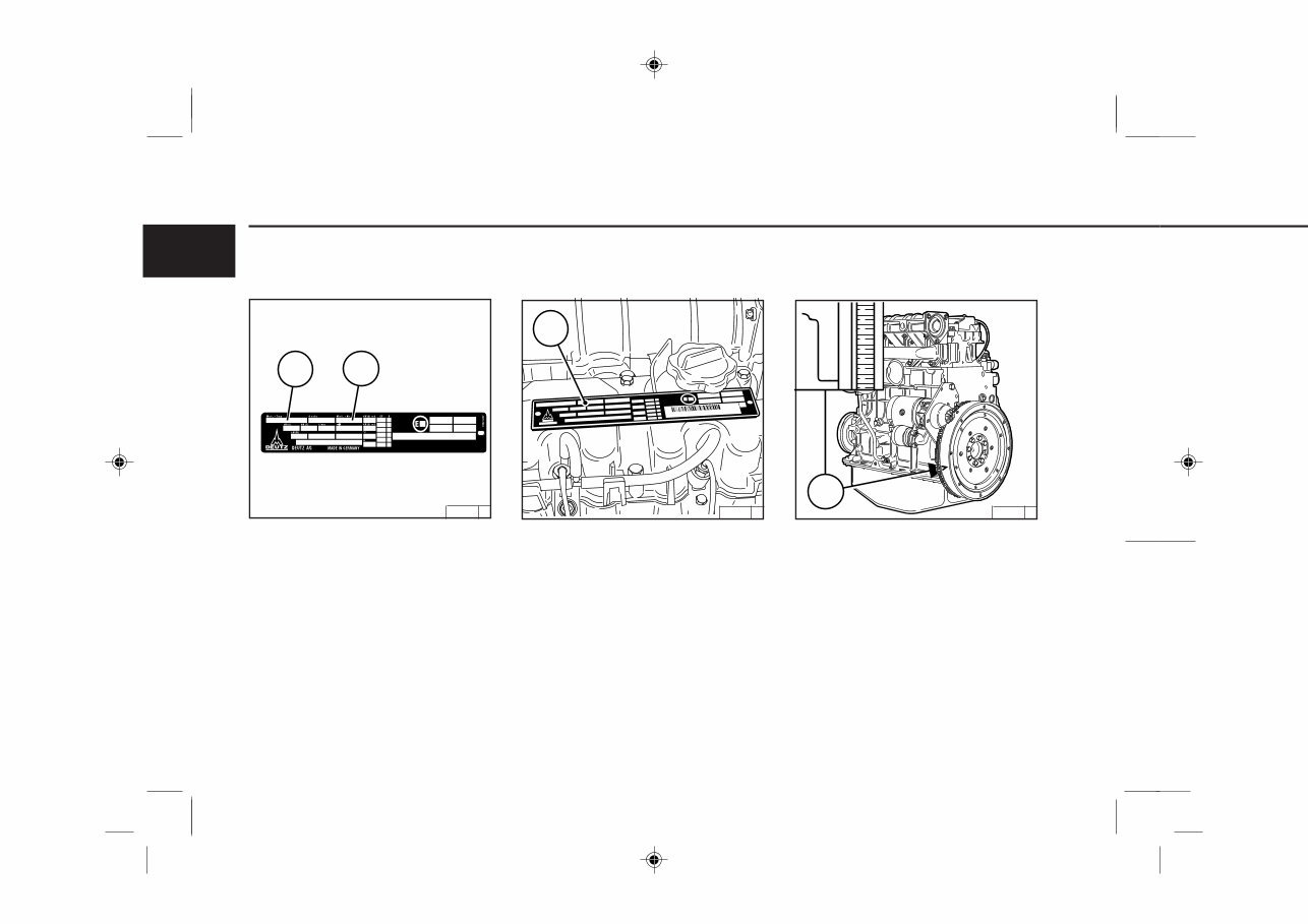
2.1.1 Rating Plate
The model A, the engine serial number B and the
performance data are stamped on the rating plate.
The model and engine serial number must be given
when ordering parts.
2.1.2 Rating Plate Location
The rating plate C is attached to the valve cover.
2.1.3 Engine Serial Number
The engine serial number B is stamped on the
crankcase D as well as the rating plate.
2.1 Model
A
B
7343en_k02_pdf 05.10.1999, 9:21 Uhr 10
11 Gerade
2
11
26 431 0
26 387 0
!
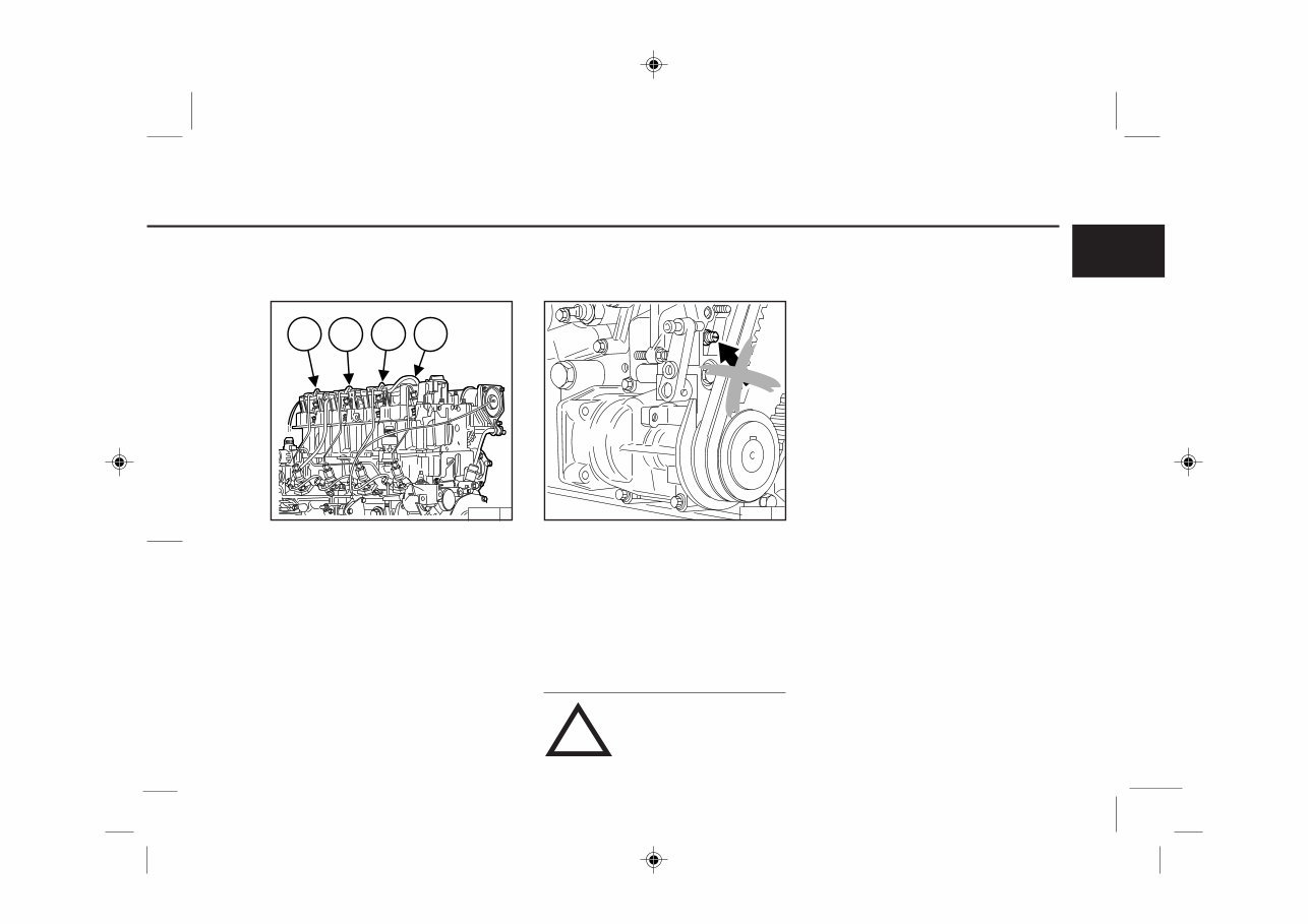
2.1.4 Cylinder Numbering
2.1 Model
Cylinders are numbered consecutively, beginning
at the flywheel end.
2.1.5 Fuel Delivery Lock
The manufacturer shall not be held liable for dam-
ages resulting from adjustments made to the regu-
lator by the operator.
The lock screws are protected in order to prevent
this:
1. with locking paint on model:
torque balancer
2. with plastic protective cap on model:
without torque balancer.
Adjustments to the regulator are to
be carried out only by authorized
DEUTZ SERVICE - specialists.
Engine Description
1 2 3 4
7343en_k02_pdf 05.10.1999, 9:21 Uhr 11
12
2
26 452 0
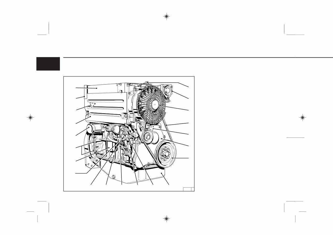
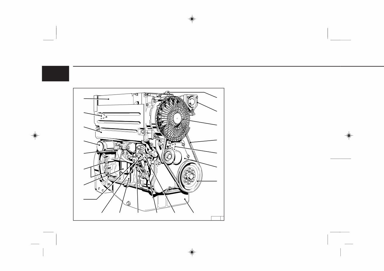
Engine Description 2.2 Engine Illustrations
2.2.1 Service Side
FL 1011F
1 Oil filler neck (valve-gear cover)
2 Charge-air line / air-intake line
3 Fan with integrated generator
4 Narrow V-belt
5 Solenoid
6 Toothed belt cover
7 V-belt pulley on crankshaft
8 Oil sump
9 Cut-out handle
10 Speed control lever
11 Oil dipstick
12 Crankshaft housing
13 Oil fill point (on side of crankcase)
14 Fuel pump
15 Easy-change fuel filter
16 Connecting facility for oil heater
17 Lube oil easy-change filter
18 Removable coolant intake hood
19 Injection pumps
20 Date plate
21 Oil cooler
21
20
18
17
16
15
14
2
3
4
5
6
7
13 12 11 10 9 8
1
19
7343en_k02_pdf 05.10.1999, 9:21 Uhr 12
13 Gerade
2
13
26444 0
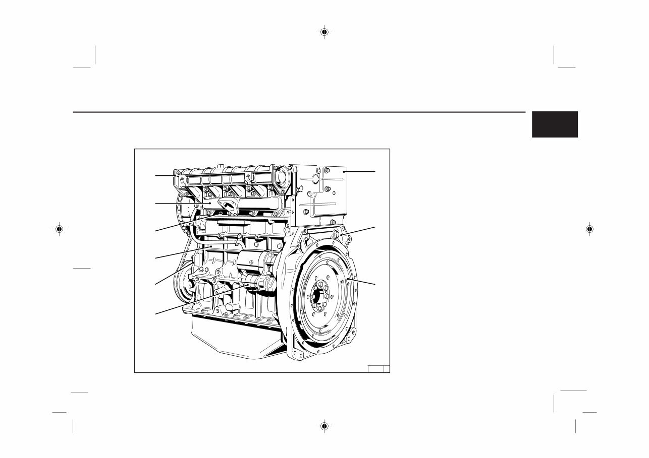
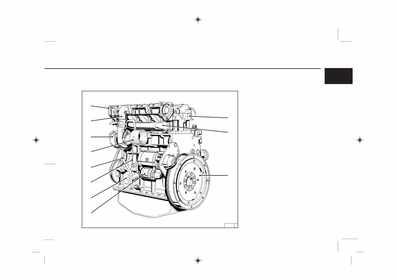
2.2 Engine Illustrations
Engine Description
22 Date plate
23 Connection housing (SAE)
24 Flywheel with ring gear
25 Starter
26 Front cover
27 Crankcase
28 Cylinder head
29 Exhaust manifold pipe
30 Air-intake pipe
2.2.2 Exhaust side
FL 1011F
30
29
28
27
26
23
24
22
25
7343en_k02_pdf 05.10.1999, 9:21 Uhr 13
14
2
26 443 0
21
20
19
18
17
16
15
14
2
3
4
5
6
7
13 12 11 10 9 8
1
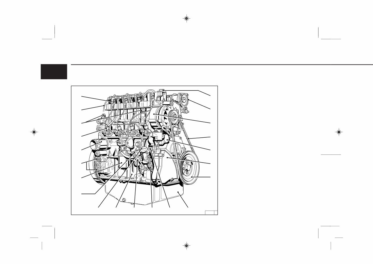
Engine Description
2.2.3 Service Side
BFL 1011F
1 Oil filler neck (valve-gear housing cover)
2 Charge-air line / air-intake line
3 Fan with integrated generator
4 Narrow V-belt
5 Solenoid
6 Wheel-house cover
7 V-belt pulley on crankshaft
8 Oil sump
9 Cut-out handle
10 Speed control lever
11 Oil dipstick
12 Crankshaft housing
13 Oil fill point (on side of crankcase)
14 Fuel pump
15 Easy-change fuel filter
16 Connection facility for oil heater
17 Charge-air pressure full-load stop (LDA)
18 Lube oil easy-change filter
19 Removable coolant intake hood
20 Injection pumps
21 Oil cooler
2.2 Engine Illustrations
7343en_k02_pdf 05.10.1999, 9:21 Uhr 14
15 Gerade
2
15
26448 0
32
31
30
29
28
27
26
22
23
24
25
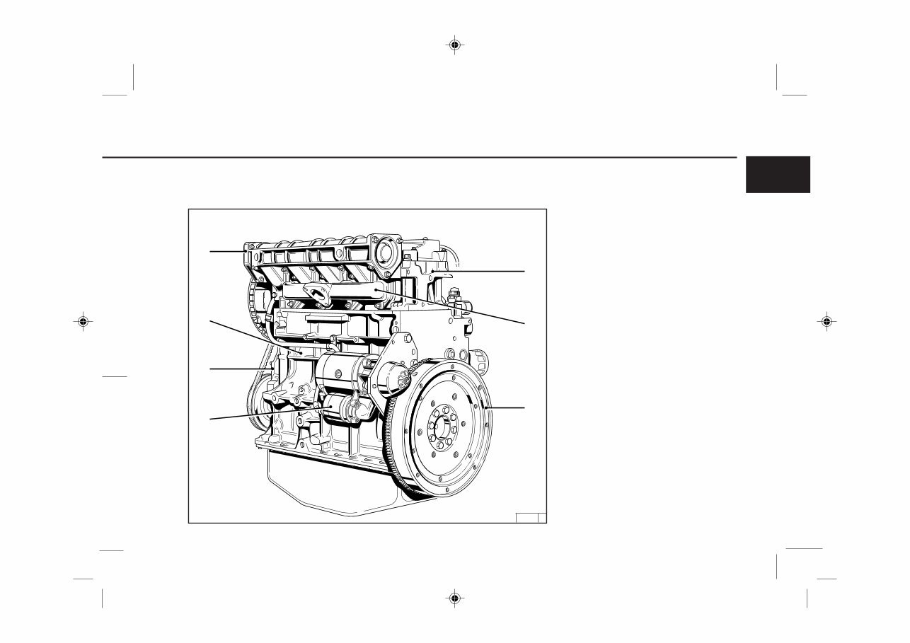
2.2.4 Exhaust side
BFL 1011F
Engine Description 2.2 Engine Illustrations
22 Cylinder head
23 Exhaust manifold pipe
24 Flywheel with ring gear
25 Starter
26 Crankshaft housing
27 Inlet line to TC (Lube oil)
28 Return line from TC (Lube oil)
29 Induction pipe
30 Turbocharger (TC)
31 Intake manifold
32 Air-intake line
7343en_k02_pdf 05.10.1999, 9:21 Uhr 15
16
2
26 453 0
21
19
17
16
15
14
2
3
4
5
6
7
13 12 11 10 9 8
1
18
20
Engine Description
2.2 Engine Illustrations
2.2.5 Service Side
FM 1011F
1 Oil filler neck (valve-gear housing)
2 Charge-air line / air-intake line
3 Generator
4 Narrow V-belt
5 Solenoid
6 Wheel-house cover
7 V-belt pulley on crankshaft
8 Oil sump
9 Cut-out handle
10 Speed control lever
11 Oil dipstick
12 Crankshaft housing
13 Oil fill point (on side of crankcase)
14 Fuel pump
15 Easy-change fuel filter
16 Connecting facility for oil heater
17 Lube oil easy-change filter
18 Injection pumps
19 Connection for oil cooler
20 Leakage-fuel line
21 Injection valves
7343en_k02_pdf 05.10.1999, 9:21 Uhr 16
17 Gerade
2
17
26 447 0
27
23
24
22
28
26
25
2.2 Engine Illustrations
Engine Description
2.2.6 Exhaust side
FM 1011F
22 Cylinder head
23 Exhaust manifold line
24 Flywheel with ring gear
25 Starter
26 Front cover
27 Crankcase
28 Intake pipe
7343en_k02_pdf 05.10.1999, 9:21 Uhr 17

18
2
26 446 0
21
20
19
18
17
16
15
14
2
3
4
5
6
7
13 12 11 10 9 8
1
Engine Description
2.2.7 Service Side
BFM 1011F
1 Oil filler neck (valve-gear housing cover)
2 Charge-air line / air-intake line
3 Generator
4 Narrow V-belt
5 Solenoid
6 Wheel-house cover
7 V-belt on crankshaft
8 Oil sump
9 Cut-out handle
10 Speed control lever
11 Oil dipstick
12 Crankshaft housing
13 Oil fill point (on side of crankcase)
14 Fuel pump
15 Easy-change fuel filter
16 Connecting facility for oil heater
17 Charge-air pressure full-load stop (TC)
18 Lube oil easy-change
19 Injection pumps
20 Oil cooler connection
21 Injection valves
2.2 Engine Illustrations
7343en_k02_pdf 05.10.1999, 9:21 Uhr 18
You're Reading a Preview
What's Included?
Fast Download Speeds
Online & Offline Access
Access PDF Contents & Bookmarks
Full Search Facility
Print one or all pages of your manual
$26.99
Deutz B-F L / B-FM 1011F - Engine Description
Viewed 93 Times Today

What's Included?
Fast Download Speeds
Online & Offline Access
Access PDF Contents & Bookmarks
Full Search Facility
Print one or all pages of your manual
$26.99

Secure transaction
What's Included?
Fast Download Speeds
Online & Offline Access
Access PDF Contents & Bookmarks
Full Search Facility
Print one or all pages of your manual
Description
- This manual contains detailed engine descriptions and specifications for the Deutz B-F L / B-FM 1011F Series, which includes models B-F L 1011F, B-F M 1011F, B-FM 1011F, B-FM 1011F-01, B-FM 1011F-02, B-FM 1011F-04, and B-FM 1011F-05.
- The descriptions cover general information, engine data, cooling system, injection system, exhaust system, fuel tank, flywheel housing, clutch, electrical equipment, transmitter, and installation dimensions. Additionally, it includes engine torque specifications, clearances, engine speed, and fuel consumption details.
- This manual offers a comprehensive overview of the Deutz B-F L / B-FM 1011F Series and serves as a valuable quick reference guide for professional mechanics and DIY enthusiasts.


