Detroit Diesel MBE 900 Series Diesel Engine Workshop Manual
What's Included?
Lifetime Access
Fast Download Speeds
Online & Offline Access
Access PDF Contents & Bookmarks
Full Search Facility
Print one or all pages of your manual
PLEASE CHECK THE BOOKMARKS OF THE LEFT-HAND SIDE OF EVERY PDF FILES FOR FIND SPECIFIC CHAPTER OR SECTION. THE BLUE REFFERENCE LINES ALL ARE AVAILABLE, FOR FIND, JUST ALWAYS OPEN THE BOOKMARK. PLEASE CONTACT US FOR FURTHER ASSISTANCE.
GENERAL INFORMATION SCOPE AND USE OF THIS MANUAL This manual contains complete instructions on operation, adjustments (including valve lash), preventive maintenance, and repair (including complete overhaul) for the MBE 900 engine. This manual was written primarily for persons servicing and overhauling the engine. In addition, this manual contains all of the instructions essential to the operators and users. Basic maintenance and overhaul procedures are common to all MBE 900 engines, and apply to all engine models. This manual is divided into numbered sections. Section one covers the engine (less major assemblies). The remaining sections cover a complete system such as the fuel system, lubrication system, or air system. Each section is divided into subsections which contain complete maintenance and operating instructions for a specific engine subassembly. Each section begins with a table of contents. Pages and illustrations are numbered consecutively within each section. Information can be located by using the table of contents at the front of the manual or the table of contents at the beginning of each section. Information on specific subassemblies or accessories within the major section is listed immediately following the section title. GENERAL DESCRIPTION The MBE 900 engine described in this manual is a water-cooled, four-stroke, direct-injection diesel engine. The cylinders are arranged inline on both the 6-cylinder and 4-cylinder models. Each has a separate fuel injection pump (unit pump) with a short injection line to the injection nozzle, which is located in the center of the combustion chamber. The unit pumps are attached to the crankcase and are driven from the camshaft. Each cylinder has two intake valves and one exhaust valve. Charge-air cooling and an exhaust gas turbocharger are standard equipment on all MBE 900 engines (wastegate turbochargers are optional). The engine has a fully electronic control system, which regulates the fuel injection quantity and timing using solenoid valves, providing extremely low-emission operation. The control system consists of an engine-resident pump and nozzle control unit (DDEC-ECU) and a vehicle control unit (DDEC-VCU). The two are connected by a proprietary datalink. Engine braking is controlled by a pneumatically-operated exhaust brake on the turbocharger and by a constant-throttle system (optional). The cylinder block has integrated oil and water channels. The upper section of the cylinder bore is induction-hardened. The single-piece cylinder head is made of cast iron. The cylinder head gasket is a three-layer, adjustment-free seal with Viton sealing elements. The pistons are made of aluminum alloy with a shallow combustion chamber recess. The pistons are cooled by oil spray nozzles. The crankshaft is precision-forged with seven main bearings (five on the 4-cylinder engine), six of which have custom-forged counterweights (four on the 4-cylinder engine), and a vibration damper at the front end. The camshaft is made of induction-hardened steel and has seven main bearings (five on the 4-cylinder Page 1 of 36 Service Doc
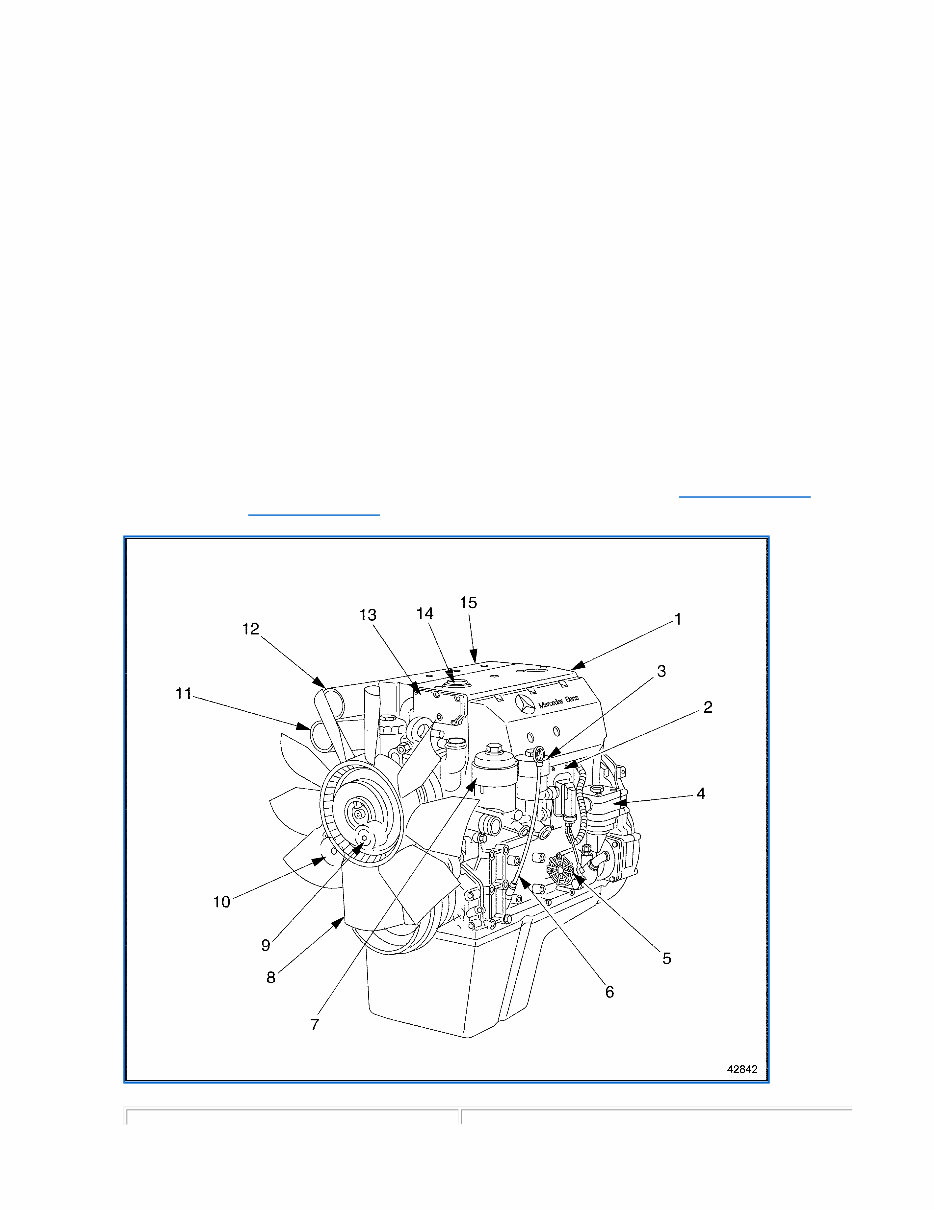
engine). Each cylinder has cams for intake and exhaust valves and a unit pump. The valves are controlled by mushroom tappets, pushrods, and rocker arms. The intake valves are opened and closed by a valve- guided bridge. There is a force-feed lubricating oil circuit supplied by a rotary oil pump. This pump is positioned at the front of the crankcase and driven by gears from the crankshaft. The oil cooler is located near the front of the crankcase on the right-hand side near the turbocharger. The gear-type fuel pump is bolted to the front of the crankcase. The pump is driven from the forward end of the camshaft. The air compressor, with a power-steering pump attached, is driven by a gear on the camshaft (optional). The vehicle is cooled by a closed system using recirculated coolant; temperature is regulated automatically by a thermostat (two thermostats on the 6-cylinder engine). The alternator and coolant pump (and other accessories) are driven by a belt with automatic belt tensioner. Electrical equipment includes a starter and an alternator. GENERAL SPECIFICATIONS AND ENGINE VIEWS For a general view of the MBE 900 4-cylinder engine, showing major components, see Figure 42842 for the left-hand side, and see Figure 42843 for the right-hand side. Page 2 of 36 Service Doc
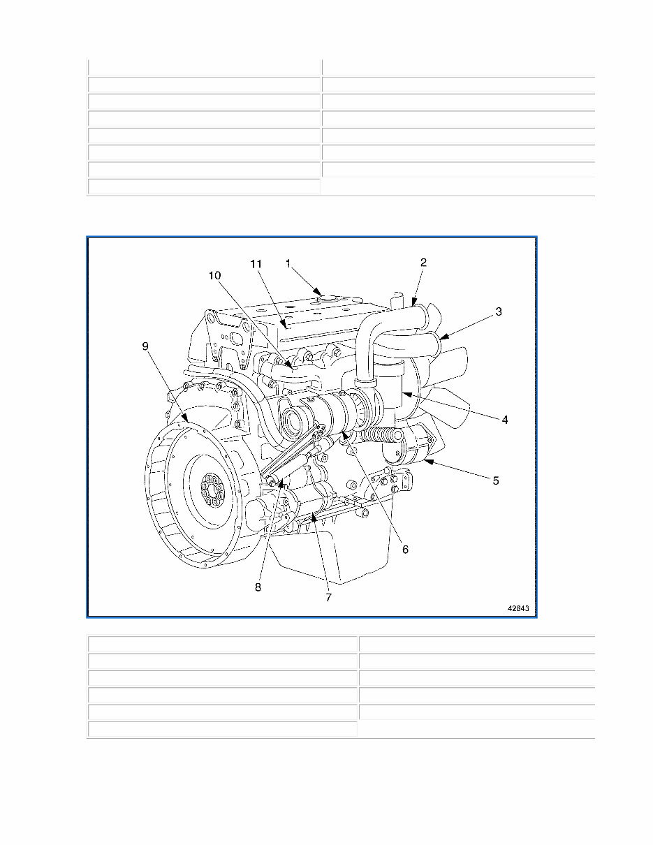
Left Side, 4-Cylinder Engine Right Side, 4-Cylinder Engine 1. Cylinder Head Cover 9. Belt Tensioner (behind fan) 2. DDEC-ECU Control Unit 10. Alternator Pulley (behind fan) 3. Fuel Pre-Filter 11. Intake Manifold Inlet 4. Air Compressor (optional) 12. Turbo Compressor Outlet 5. Power Steering Pump 13. Crankcase Breather (oil separator) 6. Oil Dipstick 14. Oil Fill Cap 7. Fuel Filter 15. Intake Manifold 8. Fan 1. Oil Fill Cap 7. Starter Motor 2. Turbo Compressor Outlet 8. Exhaust Brake (optional) 3. Intake Manifold Inlet 9. Flywheel Housing 4. Oil Filter 10. Exhaust Manifold 5. Alternator 11. Intake Manifold 6. Turbocharger Page 3 of 36 Service Doc
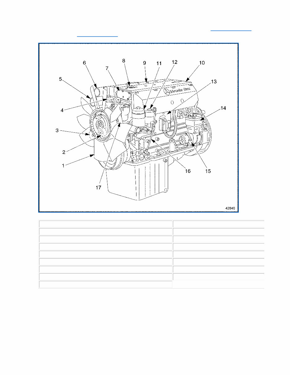
For a general view of the MBE 900 6-cylinder engine, showing major components, see Figure 42840 for the left-hand side, and see Figure 42841 for the right-hand side. Left Side, 6-Cylinder Engine 1. Fan 10. Cylinder Head Cover 2. Belt Tensioner (behind fan) 11. Fuel Filter 3. Alternator Pulley (behind fan) 12. Fuel Pre-Filter 4. Oil Filter 13. DDEC-ECU Control Unit 5. Turbo Compressor Outlet 14. Air Compressor (optional) 6. Intake Manifold Inlet 15. Power Steering Pump 7. Crankcase Breather (oil separator) 16. Oil Dipstick 8. Oil Fill Cap 17. Coolant Pump Pulley 9. Intake Manifold Page 4 of 36 Service Doc
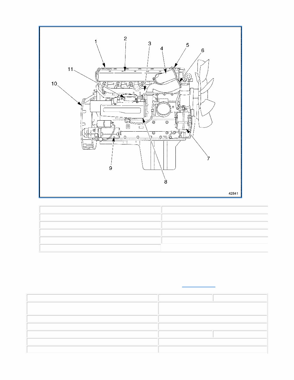
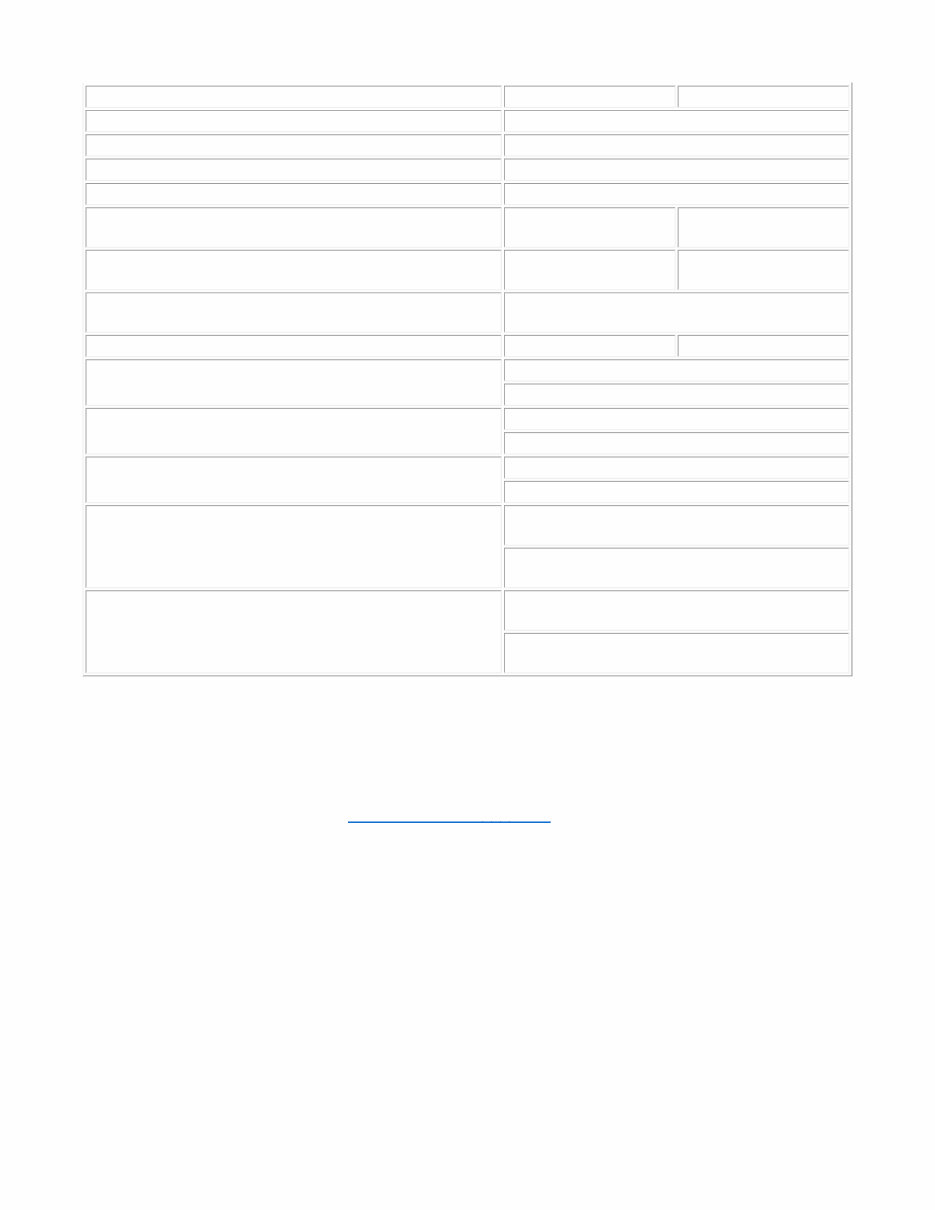
Right Side, 6-Cylinder Engine The general specifications for the MBE 900 NON-EGR engines are listed in Table . 1. Cylinder Head Cover 7. Alternator 2. Intake Manifold 8. Turbocharger 3. Exhaust Manifold 9. Starter Motor 4. Intake Manifold Inlet 10. Flywheel Housing 5. Oil Fill Cap 11. Exhaust Brake (optional) 6. Turbo Compressor Outlet Description 4-Cylinder Engines 6-Cylinder Engines Engine Type Vertical, inline cylinder block with turbocharger and charge-air cooler Cooling System Liquid Circuit Combustion Principle 4-Stroke direct-injection diesel Number of Cylinders 4 6 Bore 102 mm (4.02 in) Stroke 130 mm (5.11 in) Page 5 of 36 Service Doc
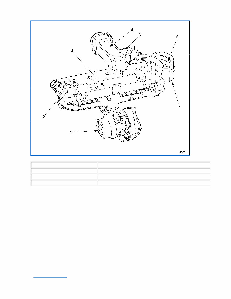
General Technical Information GENERAL DESCRIPTION OF MBE 900 EGR SYSTEM AND ENGINE VIEWS The purpose of the Exhaust Gas Recirculation (EGR) System is to reduce engine exhaust gas emissions in accordance with EPA regulations. See Figure 43621 , , , , and for EGR component locations. Displacement (total) 4.25 liters (259 in ³ ) 6.37 liters (389 in ³ ) Compression Ratio 17.4:1 Starting Speed Approximately 100 rpm Direction of Engine Rotation (viewed from flywheel) Counterclockwise Starter Electric Motor Coolant Capacity of Engine (Does not include capacity of cooling system.) Max. 8.5 liters (9.0 qt.) Max. 12.5 liters (13.2 qt.) Lubricating Oil (In standard pan, including oil filter.) Max. 15.8 liters (17.0 qt.) Max. 25.0 liters (26.4 qt.) Cold-Start Temperature Limit (Without starting aids and with battery 75 percent charged) Down to – 20 ° C ( – 4 ° F) Engine "Dry" Weight 395 kg (871 lb) 530 kg (1169 lb) Valve Lash (with engine cool) Intake = 0.40 mm (0.016 in) Exhaust = 0.60 mm (0.024 in) Valve Lift (at maximum valve clearance) Intake = 9.7 mm (0.38 in) Exhaust = 10.7 mm (0.42 in) Engine Oil Pressure At idle rpm = 50 kPa (7 psi) At maximum rpm = 250 kPa (36 psi) Fuel Injectors Minimum opening pressure = 24 500 kPa (3553 psi) Maximum opening pressure = 25 700 kPa (3727 psi) Coolant Thermostat Opening temperature = 81 ° to 85 ° C (178 ° to 185 ° F) Normal operating temperature = 95 ° C (203 ° F) Page 6 of 36 Service Doc
MBE 900 EGR System Components The EGR system consists of: Turbocharger EGR Cooler EGR Rotary Valve Reed Valves EGR Mixer The MBE 900 engines for on-highway EPA 2004 regulation applications use a water cooled EGR system. Exhaust gases from the front three cylinders on six cylinder engines (all four cylinders on four cylinder engines) are routed from the exhaust manifold through the EGR cooler, past control and reed valves (not on MBE 906), and mixed with the intake manifold charge air. The addition of cooled exhaust gases back into the combustion airflow reduces the peak in cylinder combustion temperature. Less oxides of nitrogen (NOx) are produced at lower combustion temperatures. The recycled exhaust gases are cooled before engine consumption in a twin tube-and-shell engine water cooler. See Figure 43500 . 1. Turbocharger 5. Reed Valves (Models 904, 924 and 926) 2. EGR Rotary Valve 6. Water Return Line 3. EGR Cooler 7. Water Inlet Line. 4. EGR Cool Air Mixer Page 7 of 36 Service Doc
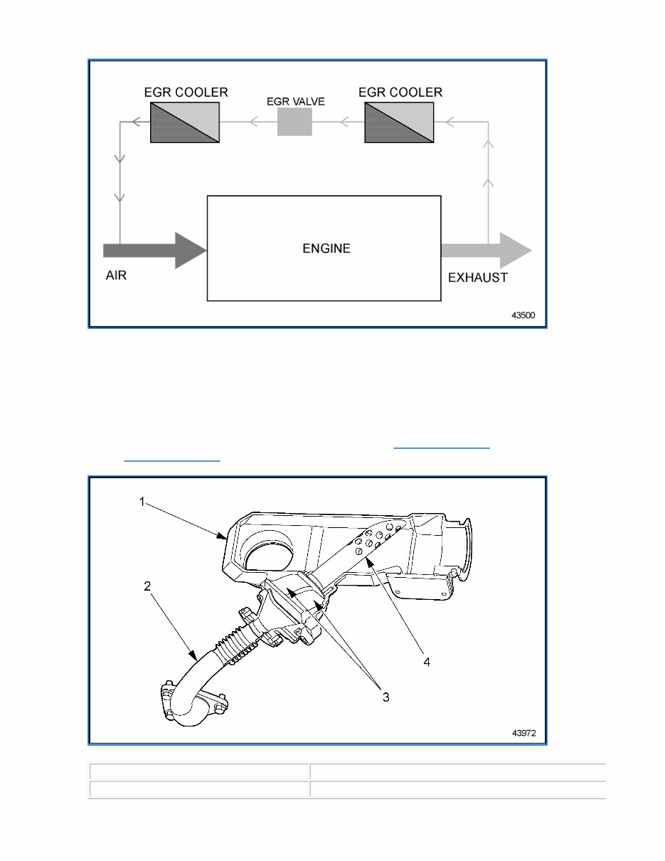
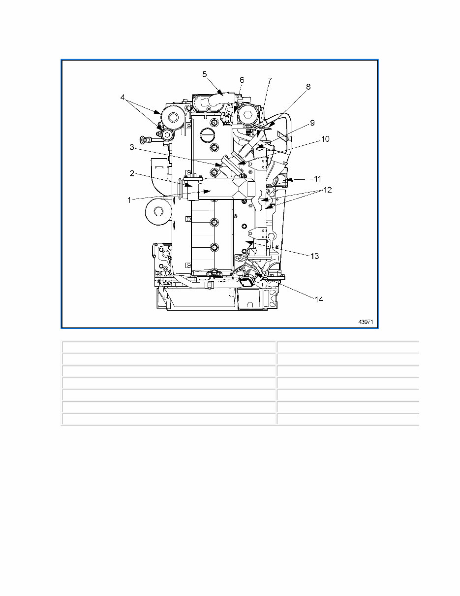
Air Flow Diagram Through Engine with EGR System The MBE 904, MBE 924 and MBE 926 engines have reed valves to assist in the transport of exhaust gasses. In order to drive exhaust gas transport to the engine, the pressure in the exhaust manifold must greater than the charge air pressure. The pressure of gasses in the exhaust manifold changes over time, peaking when the exhaust valves open. Exhaust gasses pass through the reed valves during these pressure peaks. The reed valves permit transport of exhaust gasses only during the time when the exhaust gasses pressure is greater than the charge air pressure. See Figure 43972 for the location of the reed valves. See Figure 43971 for a top view of the MBE 906 EGR engine, indicating major EGR parts. 1. Charge Air Tube Manifold 3. Reed Valves (Models 904, 924 and 926) 2. EGR Delivery Pipe 4. EGR/CA Mixer Tube (Model 906) Page 8 of 36 Service Doc
Reed Valve Location (MBE 904, MBE 924 and 926 engines only) Top View of EGR Components 1. Charge Air Tube 8. EGR Cooler Flange Heat Shield 2. Grid Heater 9. Coolant Return Tube 3. Reed Valve (904, 924 and 926 models only) 10. EGR/CA Mixer 4. Fuel Filter Pre and Main 11. Turbocharger 5. Thermostat Cover and Housing 12. EGR Cooler (upper and lower) 6. Coolant Inlet Tube 13. Charge Air Housing 7. EGR Delivery Pipe 14. EGR Rotary Valve Page 9 of 36 Service Doc
The Detroit Diesel MBE900 MBE 900 Series Diesel Engine Workshop Service Repair Manual is a comprehensive resource for professionals and DIY enthusiasts. It covers the 4.25L 4-cylinder and 6.37L 6-cylinder vertical in-line, 4-stroke, turbo-charged, direct-injection diesel EGR/non EGR engines. The manual includes detailed information on various engine systems, such as camshaft-crankshaft, cylinder head-flywheel, piston-piston ring, timing gear-valve, and more.
It also provides guidance on the air intake system, turbocharger system, cooling system, water pump, electrical equipment, engine tune-up, exhaust system, lubrication system, coolant system, ignition system, fuel system, electronic fuel control, engine sensor & connector, operation system, vitrification system, power take-off, maintenance, special equipment, storage system, service tools, and troubleshooting.
Additionally, the manual comes with operator and installation manuals. It is available in PDF format and features detailed exploded views, step-by-step procedures with illustrations, and is fully printable. Whether for repairs, maintenance, or servicing, this manual is an invaluable resource for working on Detroit Diesel MBE900 Series engines.
Compatible with operating systems: Windows 95, 98, 2000, ME, NT, XP, Vista, Windows 7 & 8, 10; Mac OS X 10.4 Tiger, Mac OS X 10.5 Leopard, Mac OS X 10.6 Snow Leopard
Requires Adobe Acrobat Reader for viewing
Recently Viewed
5,521,897Happy Clients
2,594,462eManuals
1,120,453Trusted Sellers
15Years in Business
Price:
Actual Price:
Detroit Diesel MBE 900 Series Diesel Engine Workshop Manual