Table of Contents 1 Safety 1.1 General conditions 5 1.2 Personnel and organizational requirements 6 1.3 Transportation 7 1.4 Safety regulations for startup and operation 10 1.5 Safety regulations for maintenance and repair work 11 1.6 Auxiliary materials, fire prevention and environmental protection 14 1.7 Conventions for safety instructions in the text 16 2 General Information 2.1 Engine side and cylinder designations 17 2.2 Product description 18 2.3 Engine layout 24 2.4 Sensors, actuators and injectors – Overview 26 3 Technical Data 3.1 8V 2000M84 engine data 31 3.2 10V 2000 M84 engine data 34 3.3 Firing order 37 3.4 Engine – Main dimensions 38 4 Operation 4.1 Putting the engine into operation after extended out-of-service periods (>3 months) 39 4.2 Engine – Putting into operation after scheduled out-of-service-period 40 4.3 Tasks after extended out-of-service periods (>3 weeks) 41 4.4 Checks prior to start-up 42 4.5 Fuel treatment system – Putting into operation 43 4.6 Operational checks 45 4.7 Fuel treatment system – Switching on 46 4.8 Starting the engine 47 4.9 Stopping the engine 48 4.10 Emergency stop 49 4.11 After stopping the engine 50 4.12 Fuel treatment system – Shutdown 51 4.13 Plant – Cleaning 52 5 Maintenance 5.1 Maintenance task reference table [QL1] 53 6 Troubleshooting 6.1 Fuel treatment system – Troubleshooting 54 6.2 Troubleshooting 55 7 Task Description 7.1 SOLAS 58 7.1.1 SOLAS shielding – Installation as per MTN 5233 58 7.1.2 SOLAS shielding – Installation 59 7.1.3 Installation locations for SOLAS shielding 60 7.2 Engine 66 7.2.1 Engine – Barring manually 66 7.2.2 Engine – Barring with starting equipment 67 7.3 Cylinder Liner 68 7.3.1 Cylinder liner – Endoscopic examination 68 7.3.2 Cylinder liner – Instructions and comments on endoscopic and visual examination 70 7.4 Crankcase Breather 72 7.4.1 Crankcase breather – Cleaning oil separator element 72 7.4.2 Crankcase ventilation – Oil separator element replacement, diaphragm check and replacement 73 7.5 Valve Drive 75 7.5.1 Valve clearance – Check and adjustment 75 7.5.2 Cylinder-head cover – Removal and installation 78 7.6 Injection Valve / Injector 79 7.6.1 Injector – Replacement 79 7.6.2 Injector – Removal and installation 80 7.7 Fuel System 82 7.7.1 Fuel system – Venting 82 7.8 Fuel Filter 83 7.8.1 Fuel filter – Replacement 83 7.8.2 Fuel prefilter – Differential pressure check and adjustment of gauge 85 7.8.3 Fuel prefilter – Draining 86 MS150062/01E 2012-01 | Table of Contents |3 DCL-ID: 0000017103 - 001
7.8.4 Fuel prefilter ‒ Flushing 87 7.8.5 Fuel prefilter – Filter element replacement 89 7.9 Charge-Air Cooling 91 7.9.1 Intercooler – Checking condensate drain line for coolant discharge and obstruction 91 7.10 Air Filter 92 7.10.1 Air filter – Replacement 92 7.10.2 Air filter – Removal and installation 93 7.11 Air Intake 94 7.11.1 Contamination indicator – Signal ring position check 94 7.12 Starting Equipment 95 7.12.1 Starter – Condition check 95 7.13 Lube Oil System, Lube Oil Circuit 96 7.13.1 Engine oil – Level check 96 7.13.2 Engine oil – Change 97 7.14 Oil Filtration / Cooling 98 7.14.1 Engine oil filter – Replacement 98 7.14.2 Centrifugal oil filter – Cleaning and filter- sleeve replacement 100 7.15 Coolant Circuit, General, High- Temperature Circuit 103 7.15.1 Drain and venting points 103 7.15.2 Engine coolant – Level check 109 7.15.3 Engine coolant – Change 110 7.15.4 Engine coolant – Draining 111 7.15.5 Engine coolant – Filling 112 7.15.6 HT coolant pump — Relief bore check 113 7.15.7 Engine coolant – Sample extraction and analysis 114 7.15.8 Coolant filter – Replacement 115 7.16 Raw Water Pump with Connections 116 7.16.1 Raw water pump – Relief bore check 116 7.17 Belt Drive 117 7.17.1 Drive belt – Condition check 117 7.18 Battery-Charging Generator 118 7.18.1 Battery-charging generator drive – Drive belt replacement 118 7.19 Fuel Supply System 119 7.19.1 Water drain valve – Check 119 7.19.2 Differential pressure gauge – Check 120 7.19.3 Water level probe (3-in-1 rod electrode) – Check 121 7.19.4 Pump capacity – Check 122 7.19.5 Coalescer filter element – Replacement 123 7.20 Wiring (General) for Engine/Gearbox/Unit 125 7.20.1 Engine wiring – Check 125 7.21 Accessories for (Electronic) Engine Governor / Control System 126 7.21.1 Engine governor and connectors – Cleaning 126 7.21.2 Engine governor – Checking plug-in connections 127 7.21.3 EMU – Checking plug-in connections 128 7.21.4 Engine governor – Carry out self-test 129 7.21.5 EMU and connectors – Cleaning 130 7.21.6 ECU 7 engine governor – Removal and installation 131 7.21.7 Engine monitoring unit – Removal and installation 132 8 Appendix A 8.1 Abbreviations 133 8.2 MTU contacts/service partners 136 9 Appendix B 9.1 Special Tools 137 9.2 Index 140 4 | Table of Contents | MS150062/01E 2012-01 DCL-ID: 0000017103 - 001
1 Safety 1.1 General conditions General In addition to the instructions in this publication, the applicable country-specific legislation and other com‐ pulsory regulations regarding accident prevention and environmental protection must be observed. This state-of-the-art engine has been designed to meet all applicable laws and regulations. The engine may nevertheless present a risk of injury or damage in the following cases: • Incorrect use • Operation, maintenance and repair by unqualified personnel • Modifications or conversions • Noncompliance with the Safety Instructions Correct use The engine is intended solely for use in accordance with contractual agreements and the purpose envis‐ aged for it on delivery. Any other use is considered improper use. The engine manufacturer accepts no liability whatsoever for resultant damage or injury in such case. The responsibility is borne by the user alone. Correct use also includes observation of and compliance with the maintenance specifications. Modifications or conversions Unauthorized modifications to the engine represent a safety risk. MTU will accept no liability or warranty claims for any damage caused by unauthorized modifications or conversions. Spare parts Only genuine MTU spare parts must be used to replace components or assemblies. MTU accepts no liability whatsoever for damage or injury resulting from the use of other spare parts and the warranty shall be voided in such case. Reworking components Repair or engine overhaul must be carried out in workshops authorized by MTU. MS150062/01E 2012-01 | Safety | 5 TIM-ID: 0000000860 - 017
1.2 Personnel and organizational requirements Personnel requirements Work on the engine must only be carried out by appropriately qualified and instructed personnel. Observe the minimum legal age. Responsibilities of the operating, maintenance and repair personnel must be specified by the operating company. Organizational measures This publication must be issued to all personnel involved in operation, maintenance, repair or transporta‐ tion. Keep it handy in the vicinity of the engine such that it is accessible to operating, maintenance, repair and transport personnel at all times. Use the manual as a basis for instructing personnel on engine operation and repair. In particular, person‐ nel must have read and understood the safety-relevant instructions. This is especially important for personnel who work on the engine only on an occasional basis. These persons shall receive repeated instruction. Use the Spare Parts Catalog to identify spare parts during maintenance and repair work. Working clothes and protective equipment Wear proper protective clothing for all work. Depending on the kind of work, use the necessary personal protective equipment. 6 | Safety | MS150062/01E 2012-01 TIM-ID: 0000000874 - 017
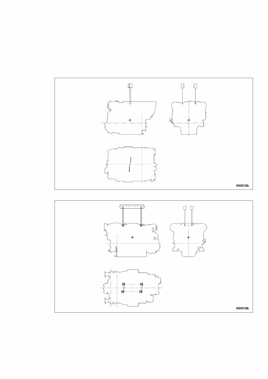
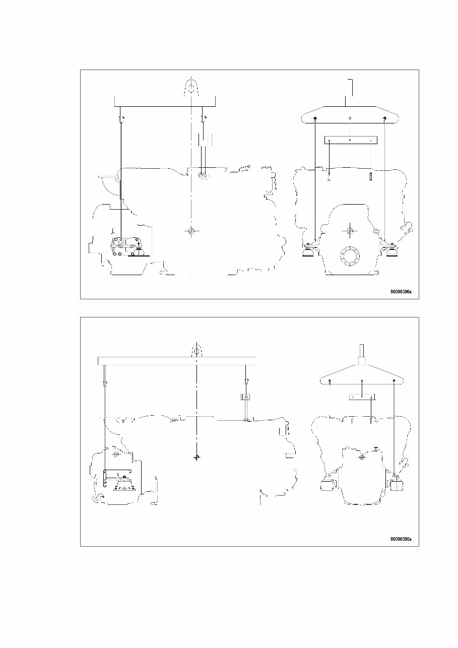
1.3 Transportation Transport without flange-mounted gearbox Illustration is essentially valid for 8V 2000 M engines Illustration is essentially valid for 12/16V 2000 M engines Transport with flange-mounted gearbox Illustration is essentially valid for 8V 2000 M engines MS150062/01E 2012-01 | Safety | 7 TIM-ID: 0000002620 - 003
Illustration is essentially valid for 12/16V 2000 M engines Only use the lifting eyes provided to lift the engine. The eyebolts mounted at the driving end and on the gearbox must not be used for transporting plants with flange-mounted gearboxes. Only use transport and lifting devices approved by MTU. Take the engine's center of gravity into account. 8 | Safety | MS150062/01E 2012-01 TIM-ID: 0000002620 - 003
The engine must only be transported in installation position, max. permissible diagonal pull 10°. If the engine is supplied with special aluminum foil packing, lift the engine at the lifting eyes of the bear‐ ing pedestal or use a means of transportation which is appropriate for the given weight (forklift truck). Install the crankshaft locking device and the locking screws for the engine mounts prior to engine trans‐ portation. Secure the engine against tilting during transport. In particular when going down inclines or ramps, the engine must be secured against moving and tilting. Setting the engine down after transport Only set down engine on a firm, level surface. Make sure that the consistency and load-bearing capacity of the ground or support surface is adequate. Never set an engine down on the oil pan unless expressively authorized to do so by MTU on a case-to- case basis. MS150062/01E 2012-01 | Safety | 9 TIM-ID: 0000002620 - 003
1.4 Safety regulations for startup and operation Safety requirements for initial operation Prior to initial operation of the unit, install the assembly or unit according to the specifications and check the installation according to the MTU specifications. Before putting the device or plant into operation, always ensure: • that all maintenance and repair work is completed, • that all loose parts have been removed from rotating machine components, • that nobody is in the danger area of moving machine parts. Immediately after putting the device or plant into operation, make sure that all control and display instru‐ ments as well as the signaling and alarm systems work properly. Safety requirements for operators The procedures for cases of emergency must be practiced regularly. The operator must be familiar with the control and display elements. The operator must be familiar with the consequences of any operations performed. During operation, the display instruments and monitoring units must be permanently observed with re‐ gard to present operating status, violation of limit values and warning or alarm messages. The following steps must be taken if a malfunction of the system is recognized or reported by the system: • inform supervisor(s) in charge, • analyze the message, • if required, carry out emergency operations e.g. emergency engine stop. Engine operation The following conditions must be fulfilled before starting the engine: • Wear ear protection. • Ensure that the engine room is well ventilated. • Do not inhale engine exhaust gases. • Ensure that the exhaust system is free of leaks and that the gases are discharged to atmosphere. • Mop up any leaked or spilt fluids and lubricants immediately or soak up with a suitable binding agent. • Protect battery terminals, battery-charger terminals and cables against accidental contact. • When the engine is running, never release coolant, oil, fuel, compressed-air or hydraulic lines. Operation of electrical equipment When electrical equipment is in operation, certain components of these appliances are electrically live. Observe the safety instructions for these devices. 10 | Safety | MS150062/01E 2012-01 TIM-ID: 0000023743 - 009
MTU 8V, 10V, 12V, 16V, 18V, 20V, 6R Series Engines Operators Manual Collection
Models covered:
12V 2000 C66
16V 2000 C66
8, 10, 12 V 1600 G10F, G20F
8, 10, 12 V 1600 G40F, G50F
8, 10, 12 V 1600 G70F, G80F
8, 12 V 1600 B30S
8, 10 V 1600, B40S, B50F
12 V 1600, B40S
8, 10, 12 V 1600 G10S, G20S
8, 10, 12 V 1600 G70S, G80S
20 V 4000 G23 with 6 exhaust turbochargers
20 V 4000 G43 with 6 exhaust turbochargers
20 V 4000 G63 with 6 exhaust turbochargers
20 V 4000 G63L with 6 exhaust turbochargers
20 V 4000 G83 with 6 exhaust turbochargers
20 V 4000 G83L with 6 exhaust turbochargers
12 V 4000 G21R
12 V 4000 G41R
12 V 4000 G73
16 V 4000 G73
8 V 4000 L62
12 V 4000 L62
16 V 4000 L62
8 V 4000 L63
20 V 4000 L63
8 V 4000 M40A
8 V 4000 M40B
8 V 2000 M50A, M50B
8 V 2000 M51A, M51B
12 V 2000 M50A, M50B
12 V 2000 M51A, M51B
16 V 2000 M50A, M50B
16 V 2000 M51A, M51B
8 V 2000 M70
12 V 2000 M70
16 V 2000 M70
V 4000 M70
V 4000 M71
8 V 2000 M72
10 V 2000 M72
12 V 2000 M72
16V 2000 M72
8 V 2000 M84
10 V 2000 M84
12 V 2000 M84
16 V 2000 M84
12 V 2000 M92
16 V 2000 M92
20 V 4000 M93
20 V 4000 M93L
12 V 2000 M94
16 V 2000 M94
12 V 2000 S96
16 V 2000 S96
12 V 2000 G25, G25 TB
12 V 2000 G45, G45 TB
12 V 2000 G65, G65 TB
12 V 2000 G85, G85 TB
16 V 2000 G25, G25 TB
16 V 2000 G45, G45 TB
16 V 2000 G65, G65 TB
16 V 2000 G85, G85 TB
18 V 2000 G25, G25 TB
18 V 2000 G45, G45 TB
18 V 2000 G65, G65 TB
18 V 2000 G85, G85 TB
12 V 4000 G23, G43, G63, G83
16 V 4000 G23, G43, G63, G83, G83L
12 V 1600 R50
16 V 4000 E20
12 V 2000 P12
16 V 2000 P12
6R 1600 G10F, G20F
6R 1600 G40F, G50F
6R 1600 G70F, G80F
6R 1600 G10S, G20S
6R 1600 G70S, G80S
6R 1600 B30S, B40S
The MTU 8V, 10V, 12V, 16V, 18V, 20V, and 6R Series Engines Operators Manual Collection is the official reference for day-to-day operation and service of a wide range of MTU diesel and gas engines. Covering models across the 1600, 2000, and 4000 series, this manual provides clear factory procedures to help keep these engines reliable and performing at their best.
Inside, you’ll find model specifications, safety guidelines, lubrication schedules, and operating procedures tailored to each configuration. Fuel, cooling, and air systems are outlined with inspection points and service recommendations, while torque values, service intervals, and adjustment data make routine work more straightforward.
Built for both experienced technicians and operators who want a dependable reference, this manual keeps everything organized and accessible. Whether you’re servicing a marine application, generator set, or industrial installation, it’s a practical guide to maintaining MTU engines the right way.
Printable: Yes Language: English Compatibility: Pretty much any electronic device, incl. PC & Mac computers, Android and Apple smartphones & tablet, etc. Requirements: Adobe Reader (free)
Recently Viewed
5,521,897Happy Clients
2,594,462eManuals
1,120,453Trusted Sellers
15Years in Business
Price:
Actual Price:
MTU 8V, 10V, 12V, 16V, 18V, 20V, 6R Series Engines Operators Manual Collection