Amendment Service! Any changes in contents will be sent to you in the form of an amendment, provided you complete the reverse of this receipt card and return it to us. Maintenance Manual 12V 4000 Gx0/1 16V 4000 Gx0/1 MR20108/01E Postcard MTU Friedrichshafen GmbH Department SCT 88040 Friedrichshafen GERMANY
Please use block capitals! Please mark all filed amendments here. No. Date Name 1. 2. 3. 4. 5. 6. 7. 8. 9. 10. 11. 12. 13. 14. 15. 16. Name Manufacturer Department Fax Telephone Street Postal box number (Postal code) City Country 1. 2. 3. 4. 5. 6. 7. 8. 9. 10. 11. 12. 13. 14. 15. 16. Receipt Amendment No. MR20108/01E Publication number:
Contents – Repair Manual A General – Important information – Hazards at the workplace – Engine side and cylinder designations – Tightening specifications – Settings – Conversion tables – Publication overview – Repair of threaded bores through threaded inserts (Heli–Coil) – Abbreviations – Keyword index B Work schedules – Engine condition check – W5 Maintenance operations – Engine removal – Engine disassembly – Engine assembly – Engine run-in – Engine installation and operation C Task description – Group summary – Materials and consumables – Tools – Component removal – Component disassembly – Inspection and repair – Component assembly – Component installation
General A – 1 MR20108/01E 02–07 E MTU A001 Important information This manual is intended for use by technical personnel responsible for the maintenance and servicing of the MTU 4000 series diesel engine This handbook contains descriptions of the following: D scheduled service operations under maintenance echelons W6 D non-scheduled service operations on the individual assemblies REMAN assemblies The following assemblies are available only in the replacement procedure: D Cylinder head D High-pressure pump D Injector D Coolant pump D MDEC D Exhaust Turbocharger D Intercooler D Vibration damper D Starter D Alternator (generator) D Fuel delivery pump Only removal and installation is explained. Structure of this handbook This manual is divided into 3 main sections: D Section A General D Section B Work schedules D Section C Task description Section C is further subdivided into main function groups (MFG) and function groups (FG). The structure is orien- ted toward the logical structure of the parts list and Spare Parts Catalogues. Each function group (FG) consists of no more than nine parts: D C.011.0501 Overview drawing D C.011.0502 Special tools D C.011.0504 Before-removal operations D C.011.0505 Removal D C.011.0506 Disassembly D C.011.0508 Inspection and repair D C.011.0510 Assembly D C.011.0511 Installation D C.011.0512 After-installation operations Systematic searches for specific information and rapid orientation in the manual are supported by: D The contents sheet, which cross-references the tables of contents of the individual groups. D An alphabetical subject index in Section A provides direct access to the individual Groups. D The Group Summary at the start of Section C lists the individual main function groups. Requirements for maintenance tasks If the maintenance work is carried out by the customer, the following must be ensured: D All safety regulations are observed D Use of trained and qualified personnel D Suitable workshop equipment with general tools D Suitable test equipment D Approved special tools
General A – 2 02–07 MR20108/01E E MTU General Assembly Instructions D Component cleanness: Areas of all components that come into contact with oil, fuel, coolant and combustion air must be clean. D Components requiring “special cleanness” (e.g. oil and fuel-carrying parts) must be cleaned with suitable clea- ning procedures before assembly, checked for particular cleanness and treated accordingly. D Component packaging must only be removed immediately before installation. D Elastomer components (e.g. rubber and similar) must not be washed with diesel fuel, solvent or cold cleaners. – Parts dirtied with oil and fuel must be cleaned immediately. The parts should be wiped with a dry cloth. – Elastomer components such as engine mounts, damping elements, couplings and V-belts must not be painted. They can only be installed after painting the engine or must be covered before painting work is car- ried out. D Radial-lip shaft seals treated by the manufacturer with oil show as a result definite signs of swelling when deli- vered. They must therefore be cleaned (not washed) only with an abrasion-proof paper cloth before installa- tion. D The surfaces of parts that slide against each other must be lubricated with SAE30 engine oil when installed, unless otherwise specified. D O-rings and surfaces moving against them during installation (bores and shafts) must be coated with petro- leum jelly, unless otherwise specified. When installing O-rings with counterrings in coolant pumps, always follow the installation instructions. D After installing O-rings in shaft grooves, in order to remedy twists caused by installation, pass a rounded mar- king tool under the O-ring in the direction of the circumference if the O-ring diameter is sufficiently large. Make sure that the O-ring is not damaged. D Before installing shaft seals – On the shaft, the sealing lip of the shaft seal must be coated with petroleum jelly and the shaft running sur- face with thin-film lubricant or SAE 30 engine oil. – In the support bore, the outer surface of metal outer jackets – unless otherwise specified in the drawing – must be coated with surface sealant. In the case of an elastomer outer jacket or combined metal/elastomer outer jacket, the outer surface must be coated with denaturated ethanol. D This symbol applies to radial-lip shaft seals and its significance depends on its position. The arrow indicates the position of the sealing lip. D Sealing paste must be used to fix the position of flat gaskets. Sealing paste is to be thinly applied in spots on the flat gaskets or mating faces. Immediately after application of the sealing paste, the flat gaskets must be fitted to the component and then (no more than 20 minutes later) the seal components screwed together. Oil, multi-purpose grease or other materials must not be used to fix the position. D Before installing antifriction bearings, lightly lubricate the bearing seats. Only remove the bearings from their original packaging immediately before installation so they do not get dirty. Do not remove the corrosion inhibitor from the bearings in original packaging. Use petroleum spirit or acid-free kerosene to clean the antifriction bearings. After cleaning, relubricate the bearings with engine oil. – During assembly, do not apply (axial) forces to antifriction elements and do not hit the bearing rings with a hammer (use assembly aids). – Do not use an open flame to heat bearing inner races. – The temperature should be between 80 _C and 100 _C and must never exceed 120 _C. – Deep-freezing for friction bearing installation is not permissible (risk of cracking, rusting through conden- sate). D Dry bearings must not be oiled. D When installing gears, the splines must be lubricated with SAE30 engine oil.
General A – 3 MR20108/01E 02–07 E MTU D All support and mating surfaces of components (e.g. mating surfaces for centring devices, flange and sealing surfaces, joint surfaces of press fits) must be clean, polished or provided with the specified surface protection and free from warping and damage. Corrosion inhibitors (e.g. oil, grease) must be removed from support and mating surfaces. D After parts are joined which are installed by means of cooling using liquid nitrogen, all condensate must be removed and the parts coated with SAE30 engine oil. D Sensors must be coated with long-life lubricant before installation in the immersion sleeves. D Cable connections with cutting ring threaded connections must be installed in a vice and tightened, the thread first being coated with thin-film lubricant. D If components are to be marked by etching, after the etching is completed the solution must be removed by means of neutralization agent. The affected parts must then be preserved with SAE30 engine oil. D Components used in hot part areas (e.g. V-clamps, bellows, plug-in pipes) must be coated at the support and mating surfaces with assembly paste, unless otherwise specified. D The assembly surfaces of screws, nuts, washers and of parts to be tensioned must be clean and polished or provided with the specified surface protection and free from warping and damage. Corrosion inhibitors (e.g. oil, grease) must be removed. Threads and screw heads must be coated with lubricant before assembly as per tightening specifications. D Unless otherwise specified, engine oil (SAE 30) must be used as lubricant, and assembly paste in the area of hot parts. D Threaded connections without tightening specifications For threaded connections without tightening specifications, the tightening procedure can be selected as requi- red, i.e. mechanical tightening with screwdriver or normal manual tightening with an open-end wrench or box wrench is possible. In the event of mechanical tightening, the tightening torque must be taken from the gene- ral tightening specifications according to thread size and property class. D Threaded connections with tightening specifications – Torque tightening The screw connections must be tightened by hand with a torque wrench or angle-of-rotation torque wrench. The specified tightening torques must be set at the torque wrench without consideration of the specified tolerance. When using an angle-of-rotation torque wrench, the torque indicated must be within the torque specification limit value. Proceed in a similar manner with torsionally protected threaded connections. These instructions apply also to testing torque. Note: If no tolerance for tightening torque is stated, the tightening tolerance is +10% of specified torque. – Angle-of-rotation tightening The additional angles of rotation specified in the tightening specifications must be achieved and may be exceeded within the specified tolerance. If no tightening tolerance is specified, the following tolerances must be observed: +5_ for additional angle of rotation less than/equal to 90_ +10_ for additional angle of rotation greater than 90_ Before angle-of-rotation tightening, each screw head must be colour-marked so that after tightening it is possible to check that the angle of rotation is correct (exception: colour-marking is not necessary in the case of a self-monitoring NC screwdriver). – Tightening to elongation Tightening must be carried out in accordance with tightening specifications taking the tightening tolerance into consideration. Information on installation of Flexmaster pipe connection To improve adhesion between the sealing ring and pipe, as well as prevent loosening of the sealing ring, both pipe ends are to be thoroughly degreased to at least the insertion depth. Remove paint from the area near the sealing ring. The cut edges on the pipe must be deburred. Otherwise leaks may arise during installation or in operation. Note: When installing sealing rings, no oil, grease, graphite or other lubricants must be used.
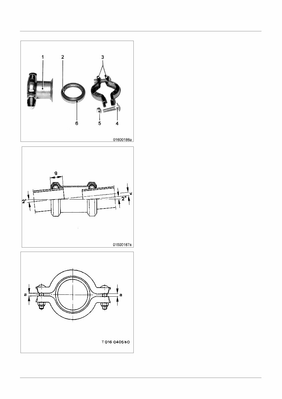
General A – 4 02–07 MR20108/01E E MTU 1 Sleeve 2 Sealing ring 3 Clamps 4 Screw 5 Self-locking nut 6 Seal carrier In event of alignment offset (v) of pipes to be con- nected, pipe ends of the sleeve must not touch. The permissible non-alignment is determined by the immersion depth of the pipe ends (g) and the per- missible angle of 2_. The depth of insertion (g) must be marked before- hand for a well centred fit. The clamp halves are placed over seal carrier and sleeve and tightened with screws and self-locking nuts until dimension “a” is achieved. Note: Replace deformed clamping-ring halves. Clamps must not be fully tightened. Replace self-locking nuts after loosening and retightening several times. Dimension “a” for pipe outer diameters: from 12 mm to 26.9 mm min. 2 mm max. 5 mm from 28 mm to 60.3 mm min. 4 mm max. 8 mm from 63.5 mm to 127 mm min. 8 mm max. 12 mm
You're Reading a Preview
What's Included?
Lifetime Access
Fast Download Speeds
Online & Offline Access
Access PDF Contents & Bookmarks
Full Search Facility
Print one or all pages of your manual
$62.99
MTU-Detroit Series 4000 12V and 16V Engine Service Manual
A complete service manual for MTU-Detroit S4000 12V and 16V engines is an essential resource for anyone involved in the maintenance and repair of these powerful engines. Whether you are a professional mechanic or a DIY enthusiast, this manual provides detailed technical information to help you understand, troubleshoot, and perform maintenance and repairs on the S4000 12V and 16V engines.
The manual covers a wide range of topics including engine specifications, maintenance procedures, troubleshooting guides, and detailed diagrams. It is an invaluable tool for ensuring the optimal performance and longevity of the MTU-Detroit S4000 12V and 16V engines.
Whether you prefer the convenience of a .PDF manual or the versatility of a .OVA file manual, this comprehensive resource equips you with the knowledge and guidance needed to effectively service these engines.
Reviews
Q&A
Recently Viewed
5,521,897Happy Clients
2,594,462eManuals
1,120,453Trusted Sellers
15Years in Business
Price:
Actual Price:
MTU-Detroit Series 4000 12V and 16V Engine Service Manual