

CUMMINS NTC-400 BC2 Diesel Engine Service Manual
What's Included?
Fast Download Speeds
Online & Offline Access
Access PDF Contents & Bookmarks
Full Search Facility
Print one or all pages of your manual
TM 9-2815-226-34-1
DIRECT SUPPORT AND GENERAL SUPPORT
MAINTENANCE SERVICE MANUAL
FOR
ENGINE, DIESEL, 6 CYLINDER
INLINE, TURBOCHARGED,
CUMMINS MODEL NTC-400 BC2
NSN 2815-01-156-6210
SEPTEMBER 1985

TM 9-2815-226-34-1
C1
Direct Support and General Support
Maintenance Service Manual
ENGINE, DIESEL, 6 CYLINDER
INLINE, TURBOCHARGED
CUMMINS MODEL NTC-400 BC 2
(2815-01-156-6210)
TM 9-2815-226-34, September 1985 is changed as follows:
1. Remove old pages and insert new pages as indicated below.
2. New or changed material is indicated by a vertical bar in the margin of the page.
3. Added or revised illustrations are indicated by a vertical bar adjacent to the illustration identification number.
4. The purpose of Change 1 to this manual is to identify configuration diffe rences between the 1980, 1982, and 1984
models. Model designators can be determined by viewing the data plate on your truck chassis.
Remove Pages Insert Pages Remove Pages Insert Pages
i i 3-139 and 3-140 3-139 and 3-140
ii ii 3-151 and 3-152 3-151 and 3-152
1-1 thru 1-4 1-1 thru 1-4 3-155 and 3-156 3-155 and 3-156
1-5/(1-6 blank) 1-5 and 1-6 3-177 thru 3-180 3-177 thru 3-180
3-29 thru 3-34 3-29 and 3-34 INDEX-1 and INDEX-2 INDEX-1 and INDEX-2
3-37 and 3-38 3-37 and 3-38
3-53 thru 3-56 3-53 thru 3-56
3-65 thru 3-68 3-65 thru 3-68.1/
(3-68.2 blank)
3-133 and 3-134 3-133 and 3-134
File this change sheet in front of the publication for reference purposes.

WARNING
EXHAUST FUMES
The following precautions must be observed to ensure the safety of personnel
when the engine of any vehicle is operated:
1. DO NOT operate personnel heater or engine of vehicle in a closed place unless the place has a lot of moving air.
2. DO NOT idle engine for long periods without ventilator blower operation. If tactical situation permits, open
hatches.
3. DO NOT drive any vehicle with inspection plates, cover plates, or engine compartment doors removed unless
necessary for maintenance purposes.
4. BE ALERT at all times during vehicle operation for exhaust odors and exposure symptoms. If either are present,
IMMEDIATELY VENTILATE personnel compartment. If symptoms persist, remove affected crew to fresh air;
keep warm; DO NOT PERMIT PHYSICAL EXERCISE; if necessary, give artificial respiration and get immediate
medical attention.
5. BE AWARE; neither the gas particulate filter un it nor the field protection mask for nuclear-biological-chemical
protection will protect you from carbon monoxide poisoning.
WARNING
COMPRESSED AIR
Compressed air used for cleaning purposes will not exceed 30 PSI (207 KPA). Use
only with effective chip guarding and personal protective equipment (goggles,
shield, gloves, etc.).
a

WARNING
FIRE AND EXPLOSION
Do not use gasoline for cleaning or as fuel.
Do not get battery electrolyte on your skin, clothing, or in your eyes. It is an acid
which can cause injury. Keep all sparks and flames away from batteries. The
battery gas is explosive.
When disconnecting battery terminals, always disconnect the ground terminal
first.
When reconnecting battery terminals, always connect the ground terminal last.
Methyl alcohol is highly flammable and poisonous, and can be absorbed through
the skin. Do not drink or breathe it. If you spill any on your skin, wash it off
immediately with water. Keep it away from sparks or flames.
Ether quick-start is explosive and poisonous. Do not permit canisters to be
subjected to excessive heat. Do not attempt to start vehicle if ether line to engine
is broken or disconnected.
When filling fuel tank with diesel fuel, be sure hose nozzle on container contacts
filler tube on fuel tank to carry off static electricity. Do not smoke, permit open
flame or uncovered battery compartments while you are servicing the diesel fuel
system.
Dry cleaning solvent P-D-680 is toxic and flammable. Wear protective goggles and
gloves and use only in well ventilated area. Avoid contact with skin, eyes, and
clothes, and do not breathe vapors. Do not use near open flame or excessive heat.
WARNING
EXHAUST PIPE AND MUFFLER
During normal operation, the exhaust pipe and muffler can become very hot. Do
not touch these components with your bare hands.
b

WARNING
ENGINE COOLANT
Take extreme care when removing engine coolant tank fill cap if temperature gage
reads above 195°F (91ºC), to prevent burns or serious injury.
WARNING
JACKING UP TRUCK
Hydraulic jack is intended for lifting the truck, not for supporting the vehicle when
performing maintenance. To prevent serious injury, do not get under truck unless
it is properly supported with blocks or jack stands.
WARNING
COOLING FAN
When working in engine compartment with the engine running, stay clear of the
cooling fan. The fan may engage automatically at any time and can cause serious
injury.
WARNING
HOISTING TRUCK
Direct personnel to stand clear during hoisting operation. Failure to do this may
cause injury to personnel.
C

TM 9-2815-226-34-1
TECHNICAL MANUAL
No. 9-2815-226-34-1
DIRECT SUPPORT AND GENERAL SUPPORT MAINTENANCE MANUAL
ENGINE, DIESEL, 6 CYLINDER INLINE, TURBOCHARGED,
CUMMINS MODEL NTC-400 BC2
REPORTING ERRORS AND RECOMMENDING IMPROVEMENTS
You can help improve this manual. If you find any mistakes or if you know of a way to improve the
procedures, please let us know. Mail your letter, DA Form 2028 (Recommended Changes to Publications
and Blank Forms), or DA Form 2028-2 located in the back of this manual directly to: Commander, US Army
Tank-Automotive command, ATTN: AMSTA-MBS, Warren, MI 48397-5000. A reply will be furnished to you.
VOLUME 1 OF 2
Page
CHAPTER 1 INTRODUCTION .......................................................................................................... 1-1
Section I General Information .................................................................................................. 1-1
Section II Equipment Description and Data ................................................................................. 1-3
CHAPTER 2 DIRECT SUPPORT AND GENERAL SUPPORT
MAINTENANCE INSTRUCTIONS .................................................................................. 2-1
Section I Repair Parts, Special Tools, TMDE, and......................................................................
Support Equipment .
Section II Troubleshooting......................................................................................................... 2-1
Section III General Maintenance ................................................................................................ 2-1
CHAPTER 3 REPAIR OF ENGINE ASSEMBLY ................................................................................. 3-1
Section I General ..................................................................................................................... 3-1
Section II Engine Disassembly................................................................................................... 3-28
Section III Cylinder Block Repair ................................................................................................. 3-57
Section IV Cylinder Liners Inspection........................................................................................... 3-115
Section V Crankshaft Assembly Repair....................................................................................... 3-117
Section VI Bearing Halves Inspection .......................................................................................... 3-126
Section VII Connecting Rod Repair .............................................................................................. 3-127
Section VIII Piston Assembly Repair ............................................................................................. 3-140
Section IX Camshaft Repair ........................................................................................................ 3-146
Change 1 i

TM 9-2815-226-34-1
Page
Section X Gear Case Cover Repair ............................................................................................ 3-150
Section XI Cylinder Head Assembly Repair .................................................................................. 3-156
Section XII Rocker Lever Housing Assembly Repair ...................................................................... 3-198
Section XIII Push Tubes Repair ................................................................................................... 3-210
Section XIV Cam Follower Housing Assembly Repair ..................................................................... 3-212
Section XV Vibration Damper Repair ........................................................................................... 3-224
Section XVI Flex Disk and Ring Gear Assembly Repair .................................................................. 3-226
VOLUME 2 OF 2
Section XVII Flywheel Housing Repair ............................................................................................ 3-229
Section XVIII Rear Cover Repair .................................................................................................... 3-230
Section XIX Rocker Lever Covers Repair ....................................................................................... 3-231
Section XX Oil Pump Assembly Repair ......................................................................................... 3-234
Section XXI Oil Pan Repair .......................................................................................................... 3-240
Section XXII Oil Cooler Assembly Repair ........................................................................................ 3-244
Section XXIII Aftercooler Repair...................................................................................................... 3-250
Section XXIV Exhaust Manifold Repair ............................................................................................. 3-253
Section XXV Accessory Drive Assembly ......................................................................................... 3-254
Section XXVI Engine Brake Assembly Repair................................................................................... 3-257
Section XXVII Fuel Injector Repair .................................................................................................... 3-262
Section XXVIII Fuel Pump Repair ..................................................................................................... 3-287
Section XXIX Turbocharger Repair ................................................................................................. 3-374
Section XXX Water Pump and Idler Pulley Assembly Repair ............................................................ 3-390
Section XXXI Engine Reassembly ................................................................................................... 3-398
Section XXXII Engine Testing .......................................................................................................... 3-462
Section XXXIII Preparation for Storage or Shipment ........................................................................... 3-472
APPENDIX A REFERENCES ............................................................................................................. A-1
APPENDIX B EXPENDABLE SUPPLIES AND MATERIALS LIST ......................................................... B-1
APPENDIX C TORQUE LIMITS .......................................................................................................... C-1
INDEX ......................................................................................................................... INDEX-1
ii

TM 9-2815-226-34-1
CHAPTER 1
INTRODUCTION
Section I. GENERAL INFORMATION
1-1. SCOPE.
a. Type of Manual:Direct Support and General Support Maintenance.
b. Model Number and Equipment Name: Cummins Model NTC-400 BC2, Six-Cylinder Inline, Turbocharged Diesel
Engine.
c. Purpose of Equipment: Engine for Truck Chassis, Direct Support Section, Topographic Support System (TSS).
1-2. MAINTENANCE FORMS, RECORDS, AND REPORTS. Department of the Army forms and procedures used for
equipment maintenance will be those prescribed by DA Pam 738-750, The Army Maintenance Management System
(TAMMS).
1-3. DESTRUCTION OF ARMY MATERIAL TO PREVENT ENEMY USE. Procedures outlined in TM 750-244-6
(Procedures for Destruction of Tank-Automotive Equipment to Prevent Enemy Use) are applicable to this equipment.
1-4. PREPARATION FOR STORAGE OR SHIPMENT. Instructions concerning storage or shipment of engine are found
in Chapter 3, Section XXXIII of this manual.
1-5. REPORTING EQUIPMENT IMPROVEMENT RECOMMENDATIONS (EIR). EIR can and must be submitted by
anyone who is aware of an unsatisfactory condition with the equipment design or use. It is not necessary to show a new
design or list a better way to perform a procedure. Just simply tell why the design is unfavorable or why a procedure is
difficult. EIR may be submitted on SF 368 (Quality Deficiency Report). Mail directly to: Commander, U.S. Army Tank -
Automotive Command, ATTN: AMSTA-QR, Warren, Michigan 48397-5000. A reply will be furnished to you.
Change 1 1-1

TM 9-2815-226-34-1
Section II. EQUIPMENT DESCRIPTION AND DATA
1-6. EQUIPMENT CHARACTERISTICS, CAPABILITIES, AND FEATURES. The following information describes engine
characteristics and features:
Camshaft: 2-1/2 inch diameter gear driven camshaft which controls all valve and injector movement. Made
of induction hardened alloy steel. Camshaft followers are roller type.
Connecting Rods: Drop forged, rifle drilled for pressure lubrication.
Crankshaft: High tensile strength steel forging. Bearing journals and fillets induction hardened. Fully
counterweighted.
Cylinder Block: Alloy cast iron with removable, wet liners.
Cylinder Head: Each head serves two cylinders. Drilled fuel supply and return lines. High temperature inserts on
exhaust valve seats.
Fuel System: Integral flyweight type governor.
Injectors: Camshaft actuated top stop type.
Intake Manifold: Single pass water aftercooler.
Lubricating Oil Cooler: Demand flow.
1-2
TM 9-2815-226-34-1
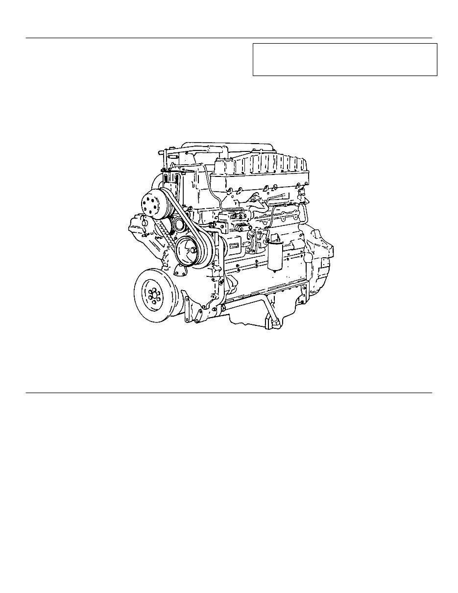
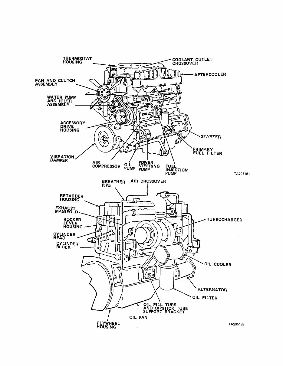
1-7. LOCATION AND DESCRIPTION OF MAJOR COMPONENTS. The illustrations below show the location of the
major engine components.
1-3
You're Reading a Preview
What's Included?
Fast Download Speeds
Online & Offline Access
Access PDF Contents & Bookmarks
Full Search Facility
Print one or all pages of your manual
$31.99
Viewed 12 Times Today


Secure transaction
What's Included?
Fast Download Speeds
Online & Offline Access
Access PDF Contents & Bookmarks
Full Search Facility
Print one or all pages of your manual
$31.99
The CUMMINS NTC-400 BC2 Diesel Engine Manual is a comprehensive resource published by the Department of the Army on 10 April 1987. It is available in two volumes, totaling 560 pages on CD-ROM. This manual is a valuable tool for both professional mechanics and DIY enthusiasts.
- Volume 1 of 2 includes:
- Introduction
- General Information
- Equipment Description and Data
- DIRECT SUPPORT AND GENERAL SUPPORT MAINTENANCE INSTRUCTIONS
- Repair Parts, Special Tools, TMDE, and Support Equipment
- Troubleshooting
- General Maintenance
- REPAIR OF ENGINE ASSEMBLY
- General
- Engine Disassembly
- Cylinder Block Repair
- Cylinder Liners Inspection
- Crankshaft Assembly Repair
- Bearing Halves Inspection
- Connecting Rod Repair
- Piston Assembly Repair
- Camshaft Repair
- Gear Case Cover Repair
- Cylinder Head Assembly Repair
- Rocker Lever Housing Assembly Repair
- Push Tubes Repair
- Cam Follower Housing Assembly Repair
- Vibration Damper Repair
- Flex Disk and Ring Gear Assembly Repair
- Volume 2 of 2 includes:
- Flywheel Housing Repair
- Rear Cover Repair
- Rocker Lever Covers Repair
- Oil Pump Assembly Repair
- Oil Pan Repair
- Oil Cooler Assembly Repair
- Aftercooler Repair
- Exhaust Manifold Repair
- Accessory Drive Assembly
- Engine Brake Assembly Repair
- Fuel Injector Repair
- Fuel Pump Repair
- Turbocharger Repair
- Water Pump and Idler Pulley Assembly Repair
- Engine Reassembly
- Engine Testing
- Preparation for Storage or Shipment


