Foreword This manual contains complete rebuild specifications and information for the N14 model engines, and all asso- ciated components manufactured by Cummins Engine Company, Inc. A listing of accessory and component suppliers’ addresses and telephone numbers is located in Section C. Suppliers can be contacted directly for any information not covered in this manual. The repair procedures in this manual are based on the engine being installed on an approved engine stand. Some rebuild procedures require the use of special service tools. Make sure the correct tools are used as described in the procedures. When a specific brand name, number, or special tool is referenced in this manual, an equivalent product can be used in place of the recommended item. A series of specific service manuals (Troubleshooting and Repair, Specifications, Alternative Repair, and so on.) are available and can be ordered by filling out and mailing the Literature Order Form located in the Service Literature Section L. Reporting of errors, omissions, and recommendations for improving this publication by the user is encouraged. Please use the postage paid, self-addressed Literature Survey Form in the back of this manual for communicating your comments. The specifications and rebuild information in this manual is based on the information in effect at the time of printing. Cummins Engine Company, Inc. reserves the right to make any changes at any time without obligation. If differences are found between your engine and the information in this manual, contact a Cummins Authorized Repair Location, a Cummins Division Office, or the factory. The latest technology and the highest quality components are used to manufacture Cummins engines. When replacement parts are needed, we recommend using only genuine Cummins or ReConT exchange parts. These parts can be identified by the following trademarks:
TABLE OF CONTENTS Page Introduction................................................................................................................................................ i-1 Group 0 - Engine Disassembly and Assembly ........................................................................................... 0-1 Group 1 - Cylinder Block........................................................................................................................... 1-1 Group 2 - Cylinder Head ........................................................................................................................... 2-1 Group 3 - Rocker Levers ........................................................................................................................... 3-1 Group 4 - Cam Followers .......................................................................................................................... 4-1 Group 5 - Fuel System.............................................................................................................................. 5-1 Group 6 - Injectors and Fuel Lines ............................................................................................................ 6-1 Group 7 - Lubricating Oil System .............................................................................................................. 7-1 Group 8 - Cooling System......................................................................................................................... 8-1 Group 9 - Drive Units ................................................................................................................................ 9-1 Group 10 - Air Intake System .................................................................................................................... 10-1 Group 11 - Exhaust System ...................................................................................................................... 11-1 Group 12 - Air Equipment ......................................................................................................................... 12-1 Group 13 - Electrical Equipment ............................................................................................................... 13-1 Group 14 - Engine Testing ........................................................................................................................ 14-1 Group 15 - Instruments and Controls ........................................................................................................ 15-1 Group 16 - Mounting Adaptations ............................................................................................................. 16-1 Group 18 - Specifications............................................................................................................................18-1 Group 20 - Vehicle Braking ....................................................................................................................... 20-1 Component Manufacturers: Names and Addresses ......................................................................................C-1 Service Literature .........................................................................................................................................L-1 Index ............................................................................................................................................................X-1 Literature Survey Form ..............................................................................................................................back
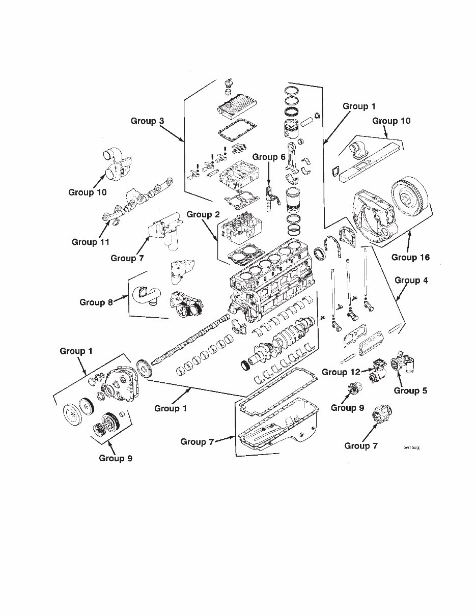
Cummins 22-Group System Exploded Diagram
Section I - Introduction Section Contents Page Engine Diagrams .............................................................................................................................................. i-13 Engine Identification ........................................................................................................................................ i-12 General Cleaning Instructions.......................................................................................................................... i-16 Glass or Plastic Bead Cleaning ...................................................................................................................... i-16 Solvent and Acid Cleaning ............................................................................................................................. i-16 Steam Cleaning ............................................................................................................................................. i-16 General Repair Instructions ............................................................................................................................... i-3 General Safety Instructions ............................................................................................................................... i-4 Important Safety Notice.................................................................................................................................... i-4 Glossary Of Terms............................................................................................................................................ i-10 Illustrations ......................................................................................................................................................... i-9 Manual Organization........................................................................................................................................... i-2 Group Contents................................................................................................................................................ i-2 Index ............................................................................................................................................................... i-2 Metric Information ............................................................................................................................................ i-2 Table of Contents............................................................................................................................................. i-2 Simbolos Usados En Este Manual .................................................................................................................... i-6 Symbole .............................................................................................................................................................. i-8 Symboles Utilises Dans Ce Manuel .................................................................................................................. i-7 Symbols Used in this Manual ........................................................................................................................... i-5 Section I - Introduction N14 Page i-1
Manual Organization All references to engine components in this manual are divided into 22 specific groups. The organization is consistent with the service bulletins, service parts topics, and the parts catalogs for your convenience in updating your copy of the shop manual. Table of Contents The Table of Contents in the front of the manual contains a quick page reference for each group number. Group Contents Each group contains the following information: • A ‘‘Section Contents’’ page at the beginning of each group to quickly aid in locating the information desired. • A Service Tools list with recommended tools needed to rebuild the components. • General information to aid in rebuilding the component and an explanation of design change differences. • Step-by-step rebuild instructions for disassembly, cleaning, inspection, and assembly of the component. • Symbols which represent the action outlined in the instructions. The definitions of the symbols, listed in four languages (English, Spanish, French, and German), appear on pages i-5 through i-8. Index An alphabetical index is in the back of the manual to aid in locating specific information. Metric Information Both metric and U.S. customary values are used in this manual. The metric value is listed first, followed by the U.S. customary in brackets. An example is 60°C [140°F]. Manual Organization Section I - Introduction N14 Page i-2
General Repair Instructions This engine incorporates the latest diesel technology; yet, it is designed to be repaired using normal repair practices performed to quality standards. • Cummins Engine Company, Inc. does not recommend or authorize any modifications or repairs to engines or components except for those detailed in Cummins Service Information. In particular, un- authorized repair to safety-related components can cause personal injury. Below is a partial listing of components classified as safety-related: Air Compressor Air Controls Air Shutoff Assemblies Balance Weights Cooling Fan Fan Hub Assembly Fan Mounting Bracket(s) Fan Mounting Capscrews Fan Hub Spindle Flywheel Flywheel Crankshaft Adapter Flywheel Mounting Capscrews Fuel Shutoff Assemblies Fuel Supply Tubes Lifting Brackets Throttle Controls Turbocharger Compressor Casing Turbocharger Oil Drain Line(s) Turbocharger Oil Supply Line(s) Turbocharger Turbine Casing Vibration Damper Mounting Capscrews • Follow All Safety Instructions Noted in the Procedures. - Follow the manufacturer’s recommendations for cleaning solvents and other substances used during the repair of the engine. Always use good safety practices with tools and equipment. • Provide A Clean Environment and Follow the Cleaning Instructions Specified in the Procedures - The engine and its components must be kept clean during any repair. Contamination of the engine and components will cause premature wear. • Perform the Inspections Specified in the Procedures. - The inspections will result in a minimal number of parts requiring replacement. The cost of the rebuild will be reduced more than the cost of the additional inspection time. • Replace all Components or Assemblies Which are Damaged or Worn Beyond the Specifications • Use Genuine Cummins New or ReConW Service Parts and Assemblies - The assembly instructions have been written to reuse as many components and assemblies as possible. When it is necessary to replace a component or assembly, the procedure is based on the use of new Cummins or Cummins ReConW components. All of the repair services described in this manual are available from all Cummins Distributors and most Dealer locations. • Follow The Specified Disassembly and Assembly Procedures to Avoid Damage to the Components. Complete troubleshooting and repair instructions are available in the Troubleshooting and Repair Manual which can be ordered or purchased from a Cummins Authorized Repair Location. Refer to Section L, Literature, for ordering instructions. Section I - Introduction General Repair Instructions N14 Page i-3
General Safety Instructions Important Safety Notice WARNING Read and understand all of the safety precautions and warnings before performing any repair. This list contains the general safety precautions that must be followed to provide personal safety. Special safety precautions are included in the procedures when they apply. • Make sure the work area surrounding the product is safe. Be aware of hazardous conditions that can exist. • Always wear protective glasses and protective shoes when working. • Do not wear loose-fitting or torn clothing. Remove all jewelry when working. • Disconnect the battery and discharge any capacitors before beginning any repair work. Disconnect the air starting motor if equipped to prevent accidental engine starting. Put a ″Do Not Operate″ tag in the operator’s compartment or on the controls. • Use ONLY the proper engine barring techniques for manually rotating the engine. Do not attempt to rotate the engine by pulling or prying on the fan. This practice can cause serious personal injury, property damage, or damage to the fan blade(s) causing premature fan failure. • If an engine has been operating and the coolant is hot, allow the engine to cool before you slowly loosen the filler cap and relieve the pressure from the cooling system. • Do not work on anything that is supported ONLY by lifting jacks or a hoist. Always use blocks or proper stands to support the product before performing any service work. • Relieve all pressure in the air, oil, and the cooling systems before any lines, fittings, or related items are removed or disconnected. Be alert for possible pressure when disconnecting any device from a system that utilizes pressure. Do not check for pressure leaks with your hand. High pressure oil or fuel can cause personal injury. • To prevent suffocation and frostbite, wear protective clothing and ONLY disconnect liquid refrigerant (freon) lines in a well ventilated area. • To avoid personal injury, use a hoist or get assistance when lifting components that weigh 23 kg [50 lb] or more. Make sure all lifting devices such as chains, hooks, or slings are in good condition and are of the correct capacity. Make sure hooks are positioned correctly. Always use a spreader bar when necessary. The lifting hooks must not be side-loaded. • Cooling System corrosion inhibitor contains alkali. Do not get the substance in your eyes. Avoid prolonged or repeated contact with skin. Do not swallow internally. In case of contact, immediately wash skin with soap and water. In case of contact, immediately flood eyes with large amounts of water for a minimum of 15 minutes. IMMEDIATELY CALL A PHYSICIAN. KEEP OUT OF REACH OF CHILDREN. • Naptha and Methyl Ethyl Ketone (MEK) are flammable materials and must be used with caution. Follow the manufacturer’s instructions to provide complete safety when using these materials. KEEP OUT OF REACH OF CHILDREN. • To avoid burns, be alert for hot parts on products that have just been turned OFF, and hot fluids in lines, tubes, and compartments. • Always use tools that are in good condition. Make sure you understand how to use them before performing any service work. Use ONLY genuine Cummins or Cummins ReconW replacement parts. • Always use the same fastener part number (or equivalent) when replacing fasteners. Do not use a fastener of lessor quality if replacements are necessary. General Safety Instructions Section I - Introduction N14 Page i-4
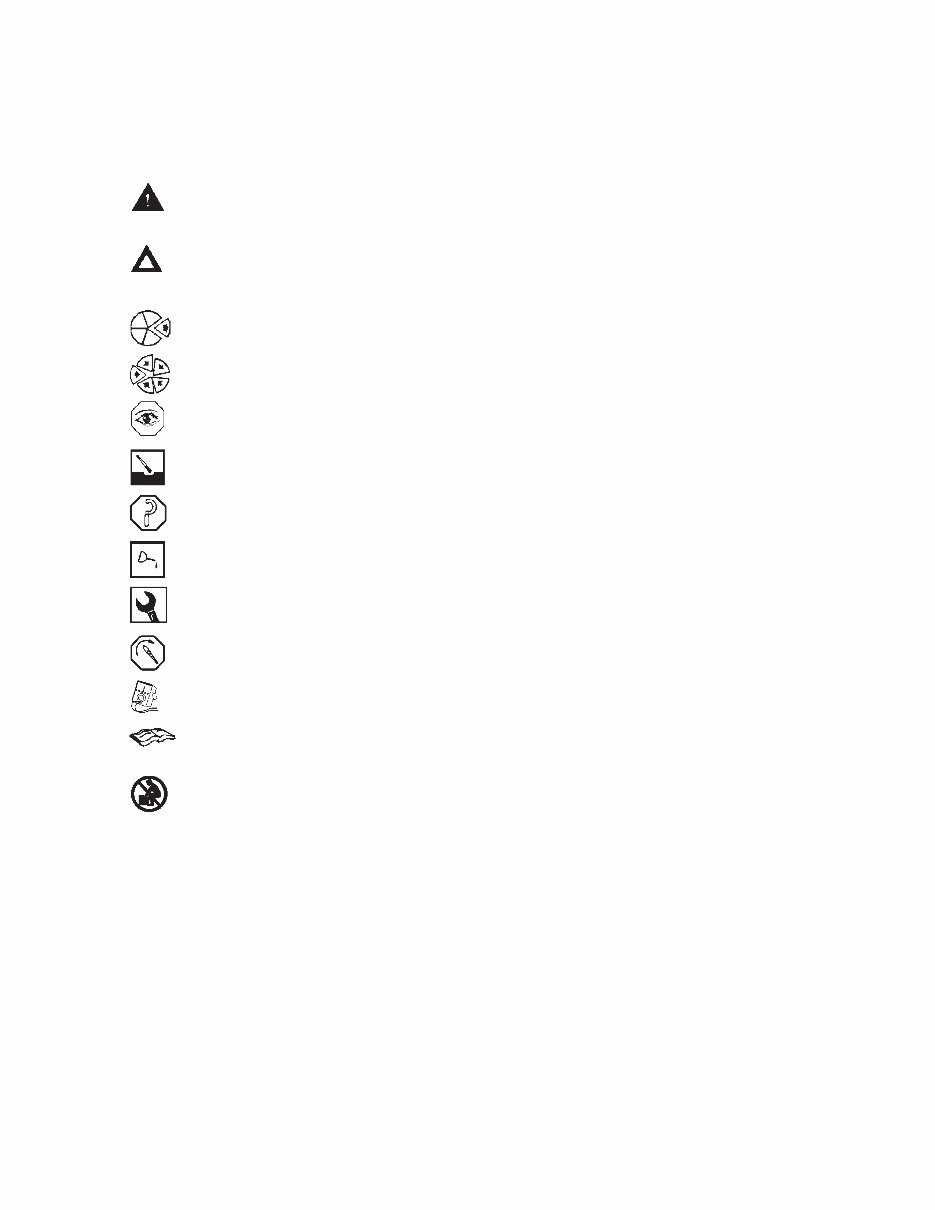
Symbols Used in this Manual The following group of symbols has been used in this manual to help communicate the intent of the instructions. When one of the symbols appears, it conveys the meaning defined below. WARNING - Serious personal injury or extensive property damage can result if the warning instructions are not followed. CAUTION - Minor personal injury can result or a part, an assembly or the engine can be damaged if the caution instructions are not followed. Indicates a REMOVAL or DISASSEMBLY step. Indicates an INSTALLATION or ASSEMBLY step. INSPECTION is required. CLEAN the part or assembly. PERFORM a mechanical or time MEASUREMENT. LUBRICATE the part or assembly. Indicates that a WRENCH or TOOL SIZE will be given. TIGHTEN to a specific torque. PERFORM an electrical MEASUREMENT. Refer to another location in this manual or another publication for additional information. The component weighs 23 kg [50 lb] or more. To avoid personal injury, use a hoist or get assistance to lift the component. Section I - Introduction Symbols Used in this Manual N14 Page i-5
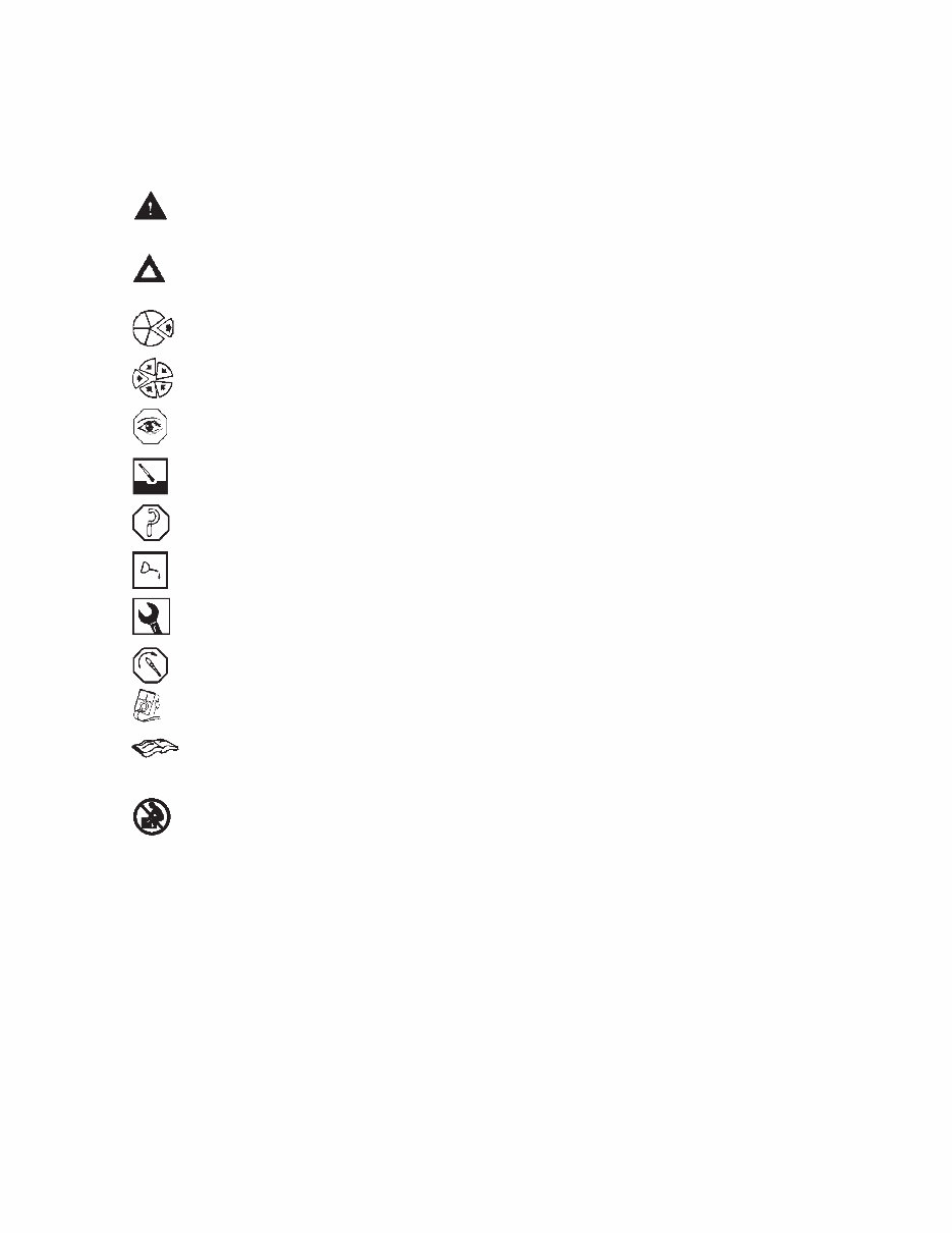
Simbolos Usados En Este Manual Los si ´mbolos siguientes son usados en este manual para clarificar el proceso de las instrucciones. Cuando aparece uno de estos si ´mbolos, su significado se especifica en la parte inferior. ADVERTENCIA - Serios dan ˜ os personales o dan ˜ o a la propiedad puede resultar si las instrucciones de Advertencia no se consideran. PRECAUCION - Dan ˜ os menores pueden resultar, o de piezas del conjunto o el motor puede averiarse si las instrucciones de Precaucio ´n no se siguen. Indica un paso de REMOCION o DESMONTAJE. Indica un paso de INSTALACION o MONTAJE. Se requiere INSPECCION. LIMPIESE la pieza o el montaje. EJECUTESE una MEDICION meca ´nica o del tiempo. LUBRIQUESE la pieza o el montaje. Indica que se dara ´ una LLAVE DE TUERCAS o el TAMAN x O DE HERRAMIENTA. APRIETESE hasta un par torsor especi ´fico. EJECUTESE una MEDICION ele ´ ctrica. Para informacio ´ n adicional refie ´rase a otro emplazamiento de este manual o a otra publicacio ´n anterior. El componente pesa 23 kg [50 lb] o mas. Para evitar dano corporal empleen una cabria u obtengan ayuda para elevar el componente. Simbolos Usados En Este Manual Section I - Introduction N14 Page i-6
The Cummins N14 Engines manual provides detailed illustrations and step-by-step instructions for repairing, rebuilding, refurbishing, or restoring your engine. It covers all diagnostic and repair procedures, as well as maintenance schedules and procedures to prevent future damage to your Cummins N14 Engines.
This repair manual consists of 587 high-quality pages containing all the necessary details to efficiently and affordably complete the job.
The index of the service manual includes:
INTRODUCTION
GROUP 0 - ENGINE DISASSEMBLY AND ASSEMBLY
GROUP 1 - CYLINDER BLOCK
GROUP 2 - CYLINDER HEAD
GROUP 3 - ROCKER LEVER HOUSING ASSEMBLY
GROUP 4 - CAM FOLLOWER ASSEMBLY
GROUP 5 - FUEL SYSTEM
GROUP 6 - INJECTORS AND FUEL LINES
GROUP 7 - LUBRICATING OIL SYSTEM
GROUP 8 - COOLING SYSTEM
GROUP 9 - DRIVE UNITS
GROUP 10 - INTAKE AIR SYSTEM
GROUP 11 - EXHAUST SYSTEM
GROUP 12 - AIR EQUIPMENT
GROUP 13 - ELECTRICAL EQUIPMENT
GROUP 14 - ENGINE TESTING
GROUP 15 - INSTRUMENTS AND CONTROLS
GROUP 16 - MOUNTING ADAPTATIONS
GROUP 18 - SPECIFICATIONS
GROUP 20 - VEHICLE BRAKING
COMPONENTS MANUFACTURERS: NAMES AND ADDRESSES
SERVICE LITERATURE
INDEX
The Cummins N14 Engines Factory Service Repair Manual is available in .PDF format. To use this service manual, you only need Adobe Reader or any compatible reader. All pages are printable with no restrictions. There are no shipping costs, and the delivery is instant. Payment can be made securely via PayPal or credit card, and upon completion, you will receive the download link instantly. For any inquiries or support, please contact us at servicemanuals@yahoo.com.