



Foreword
This manual contains complete rebuild specifications and information for the M11 model engines, and all asso-
ciated components manufactured by Cummins Engine Company, Inc. A listing of accessory and component
suppliers’ addresses and telephone numbers is located in Section C. Suppliers can be contacted directly for any
information not covered in this manual.
Read and follow all safety instructions. Refer to the WARNING in the General Safety Instructions in this
section.
The repair procedures in this manual are based on the engine being installed on an approved engine stand. Some
rebuild procedures require the use of special service tools. Make sure the correct tools are used as described in
the procedures.
When a specific brand name, number, or special tool is referenced in this manual, an equivalent product can be
used in place of the recommended item.
A series of specific service manuals (Troubleshooting and Repair, Specifications, Alternative Repair, and so on.)
are available and can be ordered by filling out and mailing the Literature Order Form located in the Service Literature
Section L.
Reporting of errors, omissions, and recommendations for improving this publication by the user is encouraged.
Please use the postage paid, self-addressed Literature Survey Form in the back of this manual for communicating
your comments.
The specifications and rebuild information in this manual is based on the information in effect at the time of printing.
Cummins Engine Company, Inc. reserves the right to make any changes at any time without obligation. If
differences are found between your engine and the information in this manual, contact a Cummins Authorized
Repair Location, a Cummins Division Office, or the factory.
The latest technology and the highest quality components are used to manufacture Cummins engines. When
replacement parts are needed, we recommend using only genuine Cummins or ReConT exchange parts. These
parts can be identified by the following trademarks:

Table of Contents
Section
Introduction ................................................................................................................................... i
Engine Identification...................................................................................................................... E
Engine Disassembly and Assembly – Group 00 ........................................................................... 0
Cylinder Block – Group 01 ............................................................................................................ 1
Cylinder Head – Group 02 ............................................................................................................. 2
Rocker Levers – Group 03............................................................................................................. 3
Cam Followers – Group 04 ............................................................................................................ 4
Fuel System – Group 05 ................................................................................................................ 5
Injectors and Fuel Lines – Group 06 ............................................................................................. 6
Lubricating Oil System – Group 07 ............................................................................................... 7
Cooling System – Group 08 .......................................................................................................... 8
Drive Units – Group 09 .................................................................................................................. 9
Air Intake System – Group 10 ....................................................................................................... 10
Exhaust System – Group 11 .......................................................................................................... 11
Air Equipment – Group 12 ............................................................................................................. 12
Electrical Equipment – Group 13 .................................................................................................. 13
Engine Testing – Group 14............................................................................................................ 14
Instruments and Controls – Group 15........................................................................................... 15
Mounting Adaptations – Group 16 ................................................................................................ 16
Specifications – Group 18 ............................................................................................................. V
Vehicle Braking – Group 20........................................................................................................... 20
Service Literature .......................................................................................................................... L
Component Manufacturers: Names and Addresses ..................................................................... C
Index ............................................................................................................................................. X
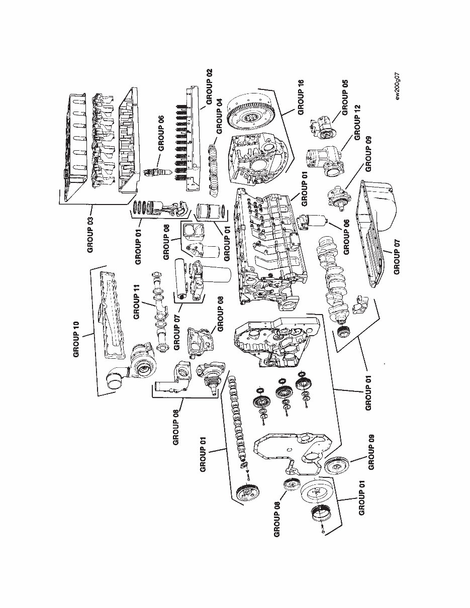
Cummins’ 22-Group System Exploded Diagram

Section i - Introduction
Section Contents
Page
About the Manual................................................................................................................................................ i-2
Definition Of Terms ........................................................................................................................................... i-11
General Cleaning Instructions .......................................................................................................................... i-10
Glass or Plastic Bead Cleaning ...................................................................................................................... i-10
Solvent and Acid Cleaning .............................................................................................................................. i-10
Steam Cleaning .............................................................................................................................................. i-10
General Repair Instructions................................................................................................................................ i-9
Welding on a CELECT™ Controlled Vehicle ....................................................................................................... i-9
General Safety Instructions ................................................................................................................................ i-8
Important Safety Notice .................................................................................................................................... i-8
How to Use the Manual....................................................................................................................................... i-2
Illustrations ......................................................................................................................................................... i-7
Simbolos ............................................................................................................................................................ i-4
Symbole .............................................................................................................................................................. i-5
Symboles ........................................................................................................................................................... i-6
Symbols ............................................................................................................................................................. i-3
Section i - Introduction
M11 Page i-1

About the Manual
This M11 Shop Manual is intended to aid mechanics in disassembly, inspecting parts for reuse, rebuilding and
assembly of components on M11 engines. The manual is divided into sections. Section 0 outlines the disassembly
and assembly of the engine while the other sections detail specific components.
How to Use the Manual
This manual is divided in the same group system used for Cummins’ filmcard system. Each group is organized
in a way that all mechanics, both those who are and are not familiar with the M11 engine models, can reference
the manual. Refer to the Table of Contents at the front of the manual to determine the group that details the desired
information.
Each group contains the following in sequence:
• Section contents at the beginning of each group to quickly aid in locating the information desired.
• Service tools list with recommended tools needed to rebuild the components.
• General information to aid in rebuilding the component, and an explanation of design change differences.
• Step-by-step rebuild instructions for disassemby, cleaning, inspection and assembly of the component.
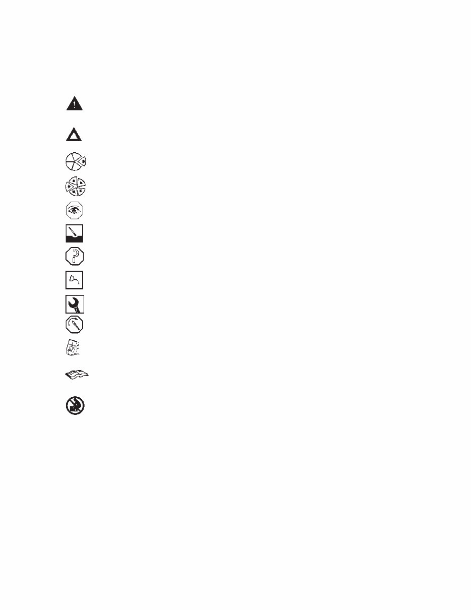
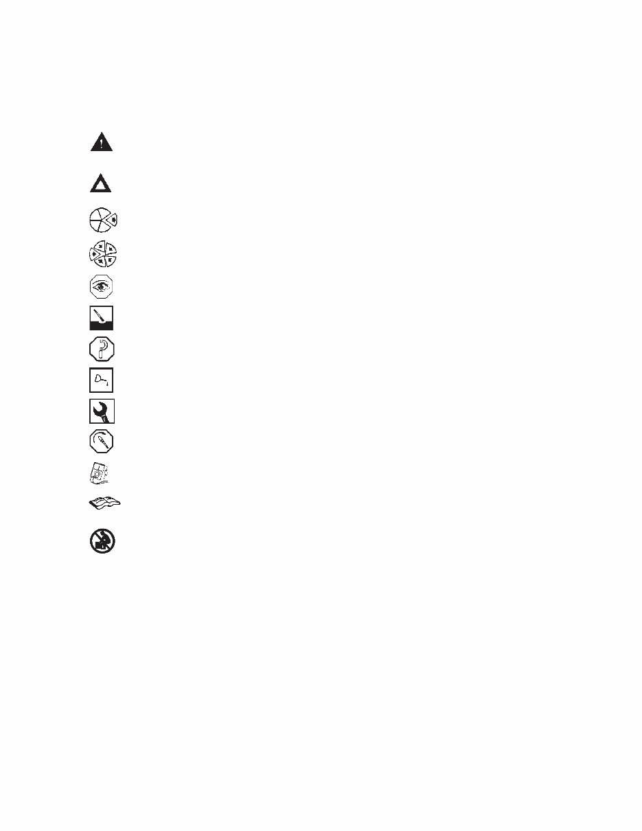
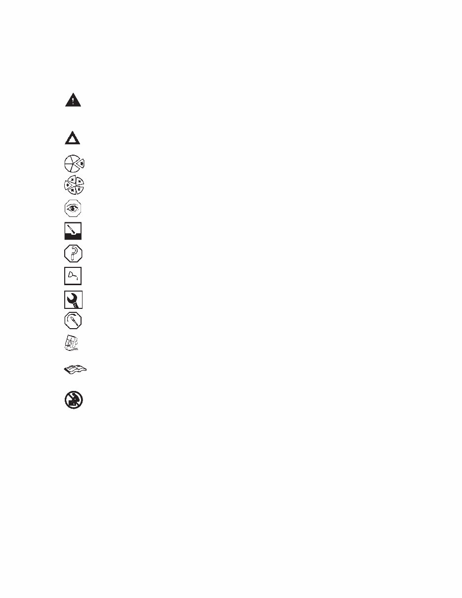
• Symbols which represent the action outlined in the instructions. The definitions of the symbols, listed in four
languages (English, Spanish, French and German), appear on pages i-3 through i-6.
Topics will be listed alphabetically on the ‘‘Section Contents’’ page. All procedures are described using the ‘‘text
symbol picture’’ (TSP) format. In general, each component rebuild will be described through a 3-step sequence
of: (1) cleaning and inspection for reuse; (2) rebuild; and (3) replacement. Reference numbers (procedure numbers)
are assigned to each process. Reference numbers are constructed with a section number and a two-digit
sequenced number.
Both metric and U.S. customary values are used in this manual. The metric value is listed first, followed by the
U.S. customary in brackets. An example is 60°C [140°].
About the Manual Section i - Introduction
M11 Page i-2
Symbols
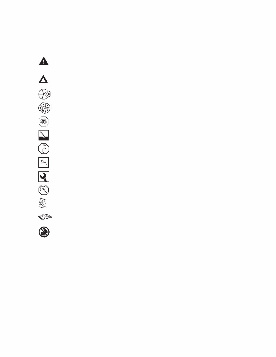
The following symbols have been used in this manual to help communicate the intent of the instructions. When
one of the symbols appears, it conveys the meaning defined below:
WARNING - Serious personal injury or extensive property damage can result if the warning
instructions are not followed.
CAUTION - Minor personal injury can result, or a part, an assembly, or the engine can be damaged
if the caution instructions are not followed.
Indicates a REMOVAL or DISASSEMBLY step.
Indicates an INSTALLATION or ASSEMBLY step.
INSPECTION is required.
CLEAN the part or assembly.
PERFORM a mechanical or time MEASUREMENT.
LUBRICATE the part or assembly.
Indicates that a WRENCH or TOOL SIZE will be given.
TIGHTEN to a specific torque.
PERFORM an electrical MEASUREMENT.
Refer to another location in this manual or another publication for additional information.
The component weighs 23 kg [50 lb] or more. To avoid personal injury, use a hoist or get assistance
to lift the component.
Section i - Introduction Symbols
M11 Page i-3
Simbolos
Los sı ´mbolos siguientes son usados en este manual para clarificar el proceso de las instrucciones. Cuando
aparece uno de estos sı ´mbolos, su significado se especifica en la parte inferior.
ADVERTENCIA - Serios dan ˜os personales o dan ˜o a la propiedad puede resultar si las instruc-
ciones de Advertencia no se consideran.
PRECAUCION - Dan ˜os menores pueden resultar, o de piezas del conjunto o el motor puede
averiarse si las instrucciones de Precaucio ´n no se siguen.
Indica un paso de REMOCION o DESMONTAJE.
Indica un paso de INSTALACION o MONTAJE.
Se requiere INSPECCION.
LIMPIESE la pieza o el montaje.
EJECUTESE una MEDICION meca ´nica o del tiempo.
LUBRIQUESE la pieza o el montaje.
Indica que se dara ´ una LLAVE DE TUERCAS o el TAMAN
˜
O DE HERRAMIENTA.
APRIETESE hasta un par torsor especı ´fico.
EJECUTESE una MEDICION ele ´ ctrica.
Para informacio ´n adicional refie ´rase a otro emplazamiento de este manual o a otra publicacio ´n
anterior.
El componente pesa 23 kg [50 lb] o mas. Para evitar dano corporal empleen una cabria u obtengan
ayuda para elevar el componente.
Simbolos Section i - Introduction
M11 Page i-4
Symbole
In diesem Handbuch werden die folgenden Symbole verwendet, die wesentliche Funktionen hervorheben. Die
Symbole haben folgende Bedeutung:
WARNUNG - Wird die Warnung nicht beachtet, dann besteht erho ¨ hte Unfall- und
Bescha ¨digungsgefahr.
VORSICHT - Werden die Vorsichtsmassnahmen nicht beachtet, dann besteht Unfall- und
Bescha ¨digungsgefahr.
AUSBAU bzw. ZERLEGEN.
EINBAU bzw. ZUSAMMENBAU.
INSPEKTION erforderlich.
Teil oder Baugruppe REINIGEN.
DIMENSION - oder ZEITMESSUNG.
Teil oder Baugruppe O
¨
LEN.
WERKZEUGGRO
¨
SSE wird angegeben.
ANZUG auf vorgeschriebenes Drehmoment erforderlich.
Elektrische MESSUNG DURCHFU
¨
HREN.
Weitere Informationen an anderer Stelle bzw. in anderen Handbu ¨ chern.
Das teil weigt 23 kg [50 lb] oder mehr. Zur vermeidung von koerperverletzung winde benutzen oder
hilfe beim heben des teils in anspruch nehmen.
Section i - Introduction Symbole
M11 Page i-5
Symboles
Les symboles suivants sont utilise ´ s dans ce manuel pour aider a ` communiquer le but des instructions. Quand l’un
de ces symboles apparaı ˆt, il e ´voque le sens de ´ fini ci-dessous:
AVERTISSEMENT - De graves le ´sions corporelles ou des dommages mate ´ riels conside ´ rables
peuvent survenir si les instructions donne ´ es sous les rubriques ″Avertissement″ ne sont pas
suivies.
ATTENTION - De petites le ´sions corporelles peuvent survenir, ou bien une pie `ce, un ensemble
ou le moteur peuvent e ˆtre endommage ´ s si les instructions donne ´ es sous les rubriques ″Attention″
ne sont pas suivies.
Indique une ope ´ration de DEPOSE.
Indique une ope ´ration de MONTAGE.
L’INSPECTION est ne ´cessaire.
NETTOYER la pie `ce ou l’ensemble.
EFFECTUER une MESURE me ´canique ou de temps.
GRAISSER la pie `ce ou l’ensemble.
Indique qu’une DIMENSION DE CLE ou D’OUTIL sera donne ´ e.
SERRER a ` un couple spe ´cifique.
EFFECTUER une MESURE e ´lectrique.
Se reporter a ` un autre endroit dans ce manuel ou a ` une autre publication pour obtenir des
informations plus comple `tes.
Le composant pese 23 kg [50 lb] ou davantage. Pour eviter toute blessure, employer un appariel
de levage ou demander de l’aide pour le soulever.
Symboles Section i - Introduction
M11 Page i-6
You're Reading a Preview
What's Included?
 Lifetime Access
Fast Download Speeds
Online & Offline Access
Access PDF Contents & Bookmarks
Full Search Facility
Print one or all pages of your manual
$37.99
CUMMINS M11 Series Diesel Engine Workshop Manual
Viewed 11 Times Today

What's Included?
Lifetime Access
Fast Download Speeds
Online & Offline Access
Access PDF Contents & Bookmarks
Full Search Facility
Print one or all pages of your manual
$37.99

Secure transaction
What's Included?
Lifetime Access
Fast Download Speeds
Online & Offline Access
Access PDF Contents & Bookmarks
Full Search Facility
Print one or all pages of your manual
The CUMMINS M11 SERIES DIESEL ENGINE WORKSHOP SERVICE MANUAL provides general engine data including horsepower, engine speed at maximum output, bore and stroke, displacement, firing order, engine weight, and crankshaft rotation. The manual includes the following contents:
- INTRODUCTION
- ENGINE DISASSEMBLY
- ENGINE ASSEMBLY
- CYLINDER BLOCK
- CYLINDER HEAD
- ROCKER LEVERS
- CAM FOLLOWERS
- FUEL SYSTEM
- INJECTORS AND FUEL LINES
- LUBRICATING OIL SYSTEM
- COOLING SYSTEM
- DRIVE UNITS
- AIR INTAKE SYSTEM
- EXHAUST SYSTEM
- AIR EQUIPMENT
- ELECTRICAL EQUIPMENT
- ENGINE TESTING
- INSTRUMENTS AND CONTROLS
- MOUNTING ADAPTATIONS
- SPECIFICATIONS
- VEHICLE BRAKING
- SERVICE LITERATURE
- COMPONENT MANUFACTURERS
This comprehensive manual features detailed exploded views, step-by-step written procedures with pictures and diagrams, and is fully printable. It is the same manual used by technicians for engine repairs, maintenance, and servicing, making it useful for both professional mechanics and DIY enthusiasts.


