

Cummins K19 troubleshooting and repair manual
What's Included?
Fast Download Speeds
Online & Offline Access
Access PDF Contents & Bookmarks
Full Search Facility
Print one or all pages of your manual
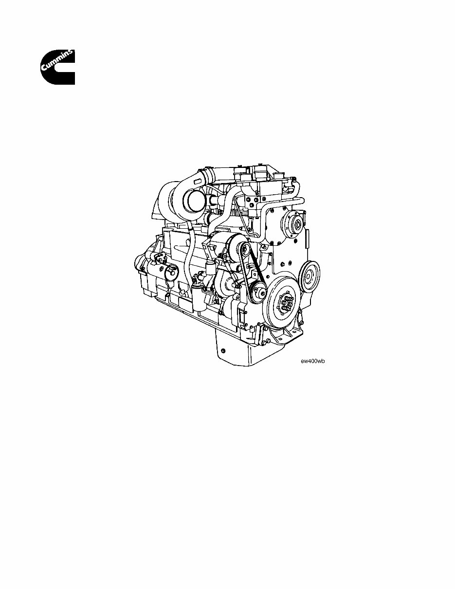
Troubleshooting and
Repair Manual
K19 Engines
CopyrightR 1986 Bulletin No. 3810307-00
Cummins Engine Company, Inc. Printed 9-86

Page 2
NOTES

Foreword
T This manual provides instructions for troubleshooting and repairing the K19 Engine in the chassis. Component
and assembly rebuild procedure are provided in the K19 Engine Shop Manual.
The manual is organized to guide a service technician through the logical steps of identifying and correcting
problems related to the engine.
This manual does not cover vehicle or equipment problems. Consult the vehicle or equipment manufacturer for
repair procedures.
A series of specific service manuals (Shop, Specifications, Alternative Repair, and so on.) are available and can
be ordered by filling out and mailing the Literature Order Form located in the Service Literature Section 14.
The repair procedures used in this manual are recommended by Cummins Engine Co., Inc. Some service
procedures require the use of special service tools. Use the correct tools as described.
Reporting of errors, omissions, and recommendations for improving this publication by the user is encouraged.
Please use the postage paid, self addressed Literature Survey Form in the back of this manual for communicating
your comments.
The specifications and rebuild information in this manual is based on the information in effect at the time of printing.
Cummins Engine Company, Inc. reserves the right to make any changes at any time without obligation. If
differences are found between your engine and the information in this manual, contact a Cummins Authorized
Repair Location, A Cummins Division Office, or the factory
The latest technology and the highest quality components were used to produce this engine. When replacement
parts are needed, we recommend using only genuine Cummins or ReConT exchange parts. These parts can be
identified by the following trademarks:
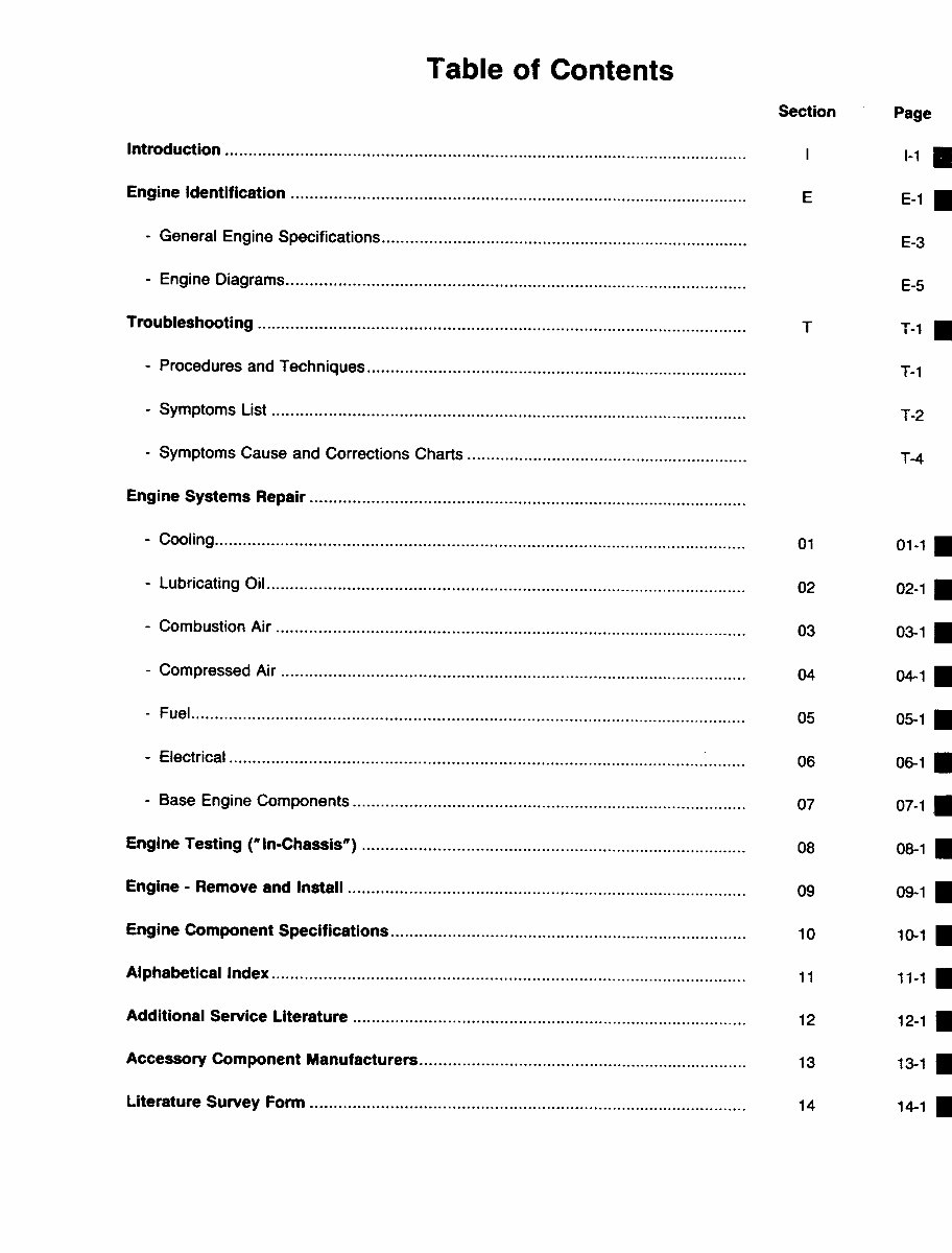

Table of Contents
Page 4
NOTES

Section i - Introduction
Section Contents
Page
About the Manual................................................................................................................................................ i-2
Definition Of Terms ........................................................................................................................................... i-11
General Cleaning Instructions .......................................................................................................................... i-10
Glass or Plastic Bead Cleaning ...................................................................................................................... i-10
Solvent and Acid Cleaning .............................................................................................................................. i-10
Steam Cleaning .............................................................................................................................................. i-10
General Repair Instructions................................................................................................................................ i-9
General Safety Instructions ................................................................................................................................ i-8
Important Safety Notice .................................................................................................................................... i-8
How to Use the Manual....................................................................................................................................... i-2
Illustrations ......................................................................................................................................................... i-7
Symbols ............................................................................................................................................................. i-3
Section i - Introduction
K19 Page i-1

About the Manual
This Troubleshooting and Repair Manual is intended to aid in determining the cause of engine-related problems
and to provide recommended repair procedures. The manual is divided into sections. Some sections contain
reference numbers and procedure numbers. The reference numbers provide general information, specifications,
diagrams, and service tools, where applicable. The procedure numbers describe specific repair procedures and
are referred to in the Troubleshooting Logic Charts.
How to Use the Manual
The manual is organized to provide an easy flow from problem identification to problem correction. A list of
troubleshooting symptoms containing the most common engine problems is on Page T-2 in the Troubleshooting
Section. Complete the following steps to locate and correct the problem:
(STEP 1.) Locate the symptom on the list.
Reference is made to the page number where the″Troubleshooting Logic Chart″ is found.
(STEP 2.) The left column of the ″Troubleshooting Logic Chart″ indicates a probable cause, starting at the
top with the simplest and easiest to repair or most likely to occur, and continuing downward to the
most difficult and least likely to occur.
The right column provides a brief description of the corrective action with a procedure number or
bulletin number reference for the repair procedure.
(STEP 3.) Locate the probable cause in the left column, and then turn to the procedure referenced in the right
column or consult the bulletin number specificed.
The repair procedures are listed by system (cooling, lubricating oil, combustion air, compressed
air, fuel, electrical, and base engine components).
(STEP 4.) The Troubleshooting Logic Charts are based on the following assumptions:
1. The engine has been installed according to the manufacturer’s specifications.
2. The easiest repairs are done first.
3. ″Generic″ solutions to cover problems with the most common applications and OEM’s (Original
Equipment Manufacturer).
About the Manual Section i - Introduction
K19 Page i-2
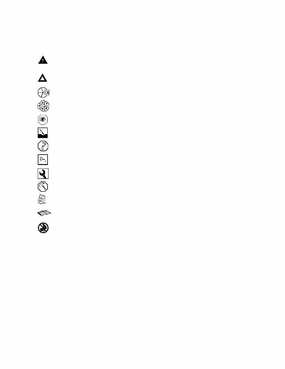
Symbols
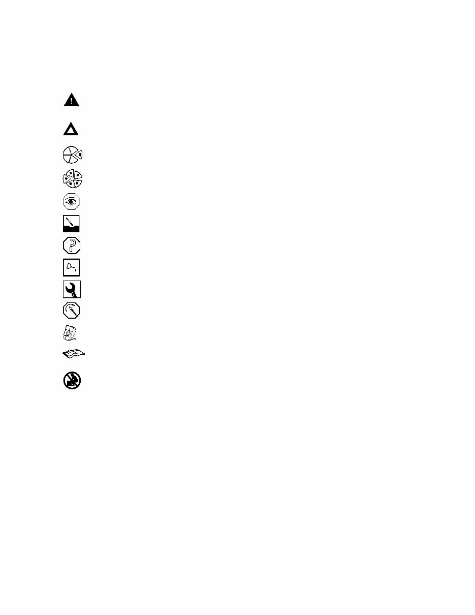
The following symbols have been used in this manual to help communicate the intent of the instructions. When
one of the symbols appears, it conveys the meaning defined below:
WARNING - Serious personal injury or extensive property damage can result if the warning
instructions are not followed.
CAUTION - Minor personal injury can result or a part, an assembly, or the engine can be damaged
if the caution instructions are not followed.
Indicates a REMOVAL or DISASSEMBLY step.
Indicates an INSTALLATION or ASSEMBLY step.
INSPECTION is required.
CLEAN the part or assembly.
PERFORM a mechanical or time MEASUREMENT.
LUBRICATE the part or assembly.
Indicates that a WRENCH or TOOL SIZE will be given.
TIGHTEN to a specific torque.
PERFORM an electrical MEASUREMENT.
Refer to another location in this manual or another publication for additional information.
The component weighs 23 kg [50 lb] or more. To avoid personal injury, use a hoist or get assistance
to lift the component.
Section i - Introduction Symbols
K19 Page i-3
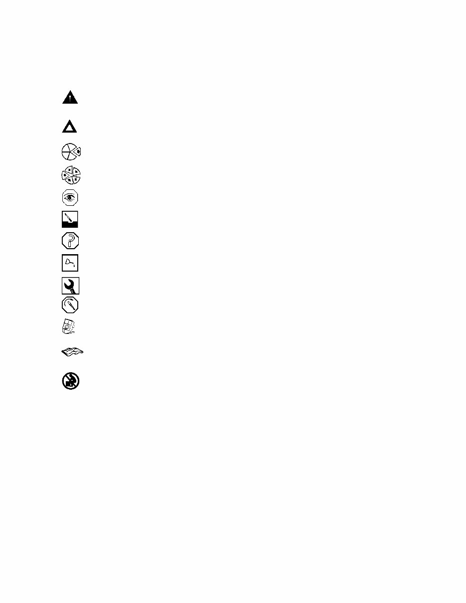
Simbolos
Los sı ´mbolos siguientes son usados en este manual para clarificar el proceso de las instrucciones. Cuando
aparece uno de estos sı ´mbolos, su significado se especifica en la parte inferior.
ADVERTENCIA - Serios dan ˜os personales o dan ˜o a la propiedad puede resultar si las instruc-
ciones de Advertencia no se consideran.
PRECAUCION - Dan ˜os menores pueden resultar, o de piezas del conjunto o el motor puede
averiarse si las instrucciones de Precaucio ´n no se siguen.
Indica un paso de REMOCION o DESMONTAJE.
Indica un paso de INSTALACION o MONTAJE.
Se requiere INSPECCION.
LIMPIESE la pieza o el montaje.
EJECUTESE una MEDICION meca ´nica o del tiempo.
LUBRIQUESE la pieza o el montaje.
Indica que se dara ´ una LLAVE DE TUERCAS o el TAMAN
˜
O DE HERRAMIENTA.
APRIETESE hasta un par torsor especı ´fico.
EJECUTESE una MEDICION ele ´ ctrica.
Para informacio ´n adicional refie ´rase a otro emplazamiento de este manual o a otra publicacio ´n
anterior.
El componente pesa 23 kg [50 lb] o mas. Para evitar dano corporal empleen una cabria u obtengan
ayuda para elevar el componente.
Symbols Section i - Introduction
K19 Page i-4
Symbole
In diesem Handbuch werden die folgenden Symbole verwendet, die wesentliche Funktionen hervorheben. Die
Symbole haben folgende Bedeutung:
WARNUNG - Wird die Warnung nicht beachtet, dann besteht erho ¨ hte Unfall- und
Bescha ¨digungsgefahr.
VORSICHT - Werden die Vorsichtsmassnahmen nicht beachtet, dann besteht Unfall- und
Bescha ¨digungsgefahr.
AUSBAU bzw. ZERLEGEN.
EINBAU bzw. ZUSAMMENBAU.
INSPEKTION erforderlich.
Teil oder Baugruppe REINIGEN.
DIMENSION - oder ZEITMESSUNG.
Teil oder Baugruppe O
¨
LEN.
WERKZEUGGRO
¨
SSE wird angegeben.
ANZUG auf vorgeschriebenes Drehmoment erforderlich.
Elektrische MESSUNG DURCHFU
¨
HREN.
Weitere Informationen an anderer Stelle bzw. in anderen Handbu ¨ chern.
Das teil weigt 23 kg [50 lb] oder mehr. Zur vermeidung von koerperverletzung winde benutzen oder
hilfe beim heben des teils in anspruch nehmen.
Section i - Introduction Symbols
K19 Page i-5
You're Reading a Preview
What's Included?
Fast Download Speeds
Online & Offline Access
Access PDF Contents & Bookmarks
Full Search Facility
Print one or all pages of your manual
$31.99
$41.99
Viewed 85 Times Today


Secure transaction
What's Included?
Fast Download Speeds
Online & Offline Access
Access PDF Contents & Bookmarks
Full Search Facility
Print one or all pages of your manual
$31.99
$41.99
This troubleshooting and repair manual is designed for the Cummins K19 engine and covers a wide range of topics over 713 pages. It is a valuable resource for both professional mechanics and DIY enthusiasts.
- SECTION I-INTRODUCTION
- SECTION E-ENGINE AND COMPONENT IDENTIFICATION
- SECTION T-TROUBLESHOOTING
- SECTION 1 COOLING SYSTEM
- SECTION 2 LUBRICATION OIL SYSTEM
- SECTION 3 COMBUSTION AIR SYSTEM
- SECTION 4 COMPRESSED AIR SYSTEM
- SECTION 5 FUEL SYSTEM
- SECTION 6 ELECTRICAL SYSTEM
- SECTION 7 BASE ENGINE COMPONENTS
- SECTION 8 ENGINE TESTING (IN CHASSIS)
- SECTION 9 ENGINE REMOVE AND INSTALL
- SECTION 10 ENGINE COMPONENT SPECIFICATIONS
- SECTION 11 INDEX- TROUBLESHOOTING AND REPAIR
- SECTION 12 SERVICE LITERATURE
- SECTION 13 COMPONENT MANUFACTURERS


