

CUMMINS A Series A2000 A2300 Engine Workshop Service Manual
What's Included?
Fast Download Speeds
Online & Offline Access
Access PDF Contents & Bookmarks
Full Search Facility
Print one or all pages of your manual

A Series Troubleshooting and Repair Manual Definition of Terms 5
About the Manual
The procedures in this manual were developed for an in-chassis environment. The information has been grouped
by the main engine systems. The Table of Contents defines the systems. The index at the beginning of each
section subdivides the instructions for the various components of the system. Wrench sizes and special tools are
identified in the procedures as needed.
How to Use the Manual
The organization of this manual is based on the troubleshooting logic presented in Section 2. To fix a problem, find
the logic chart for the particular symptom. Follow the steps specified until the problem is corrected.
The left column of the charts indicates a probable cause. The right column provides a brief description of the
corrective action with a reference to the repair procedure or diagnostic discussion when appropriate.
The logic charts reflect three basic considerations:
1. Assumes the engine has provided satisfactory service prior to the problem.
2. Performing the easiest things first.
3. Most logical cause in descending order.
If the problem occurs with a new engine or after repair of the engine, the diagnostics discussion for each major
system will provide guidance for sorting out the cause of the problem.
A Series Troubleshooting and Repair Manual Definition of Terms 6
Generic Symbols
The following group of symbols has been used in this manual to help communicate the intent of the instructions.
When one of the symbols appears, it conveys the meaning defined below.
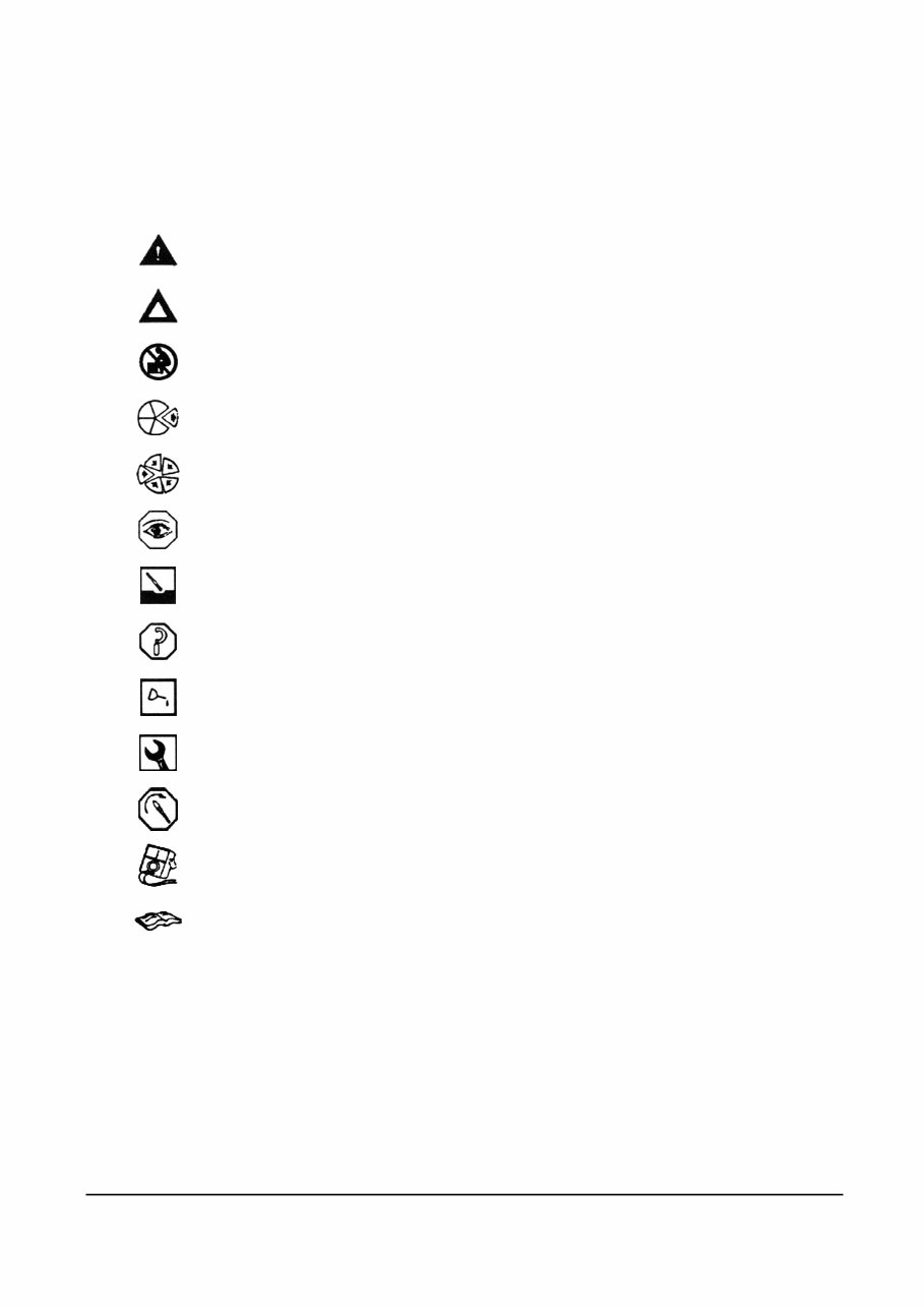
WARNING – Serious personal injury or extensive property damage can result if the
warning instructions are not followed.
CAUSION – Minor personal injury can result or a part, an assembly or the engine can be
damaged if the Caution instructions are not followed.
The component weighs 23kg [50lb] or more. To avoid personal injury, use a hoist or get
assistance to lift the component.
Indicates a REMOVAL or DISASSEMBLY step.
Indicates an INSTALLATION or ASSEMBLY step.
INSPECTION is required.
CLEAN the part or assembly.
PERFORM a mechanical or time MEASUREMENT.
LUBRICATE the part or assembly.
Indicates that a WRENCH or TOOL SIZE will be given.
TIGHTEN to a specific torque
PERFORM an electrical MEASUREMENT.
Refer to another location in this manual or another publication for additional information.
A Series Troubleshooting and Repair Manual Definition of Terms 7
Definition of Terms
The following is a list of guidelines for each procedure in the “repair Sections” of the Troubleshooting and Repair
Manual. The procedure will be given first; followed by a definition o the step or steps involved.
Check
Inspect
Test
Adjust
Visually
Inspect
Remove
Clean
Disassemble
Repair
Note
Replace
Install
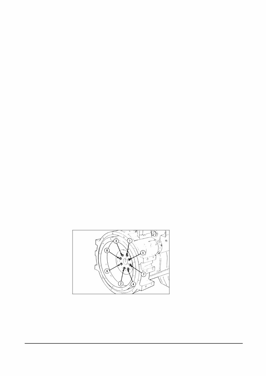
Star Pattern
Torque
Sequence
Examine a component or system for damage, excessive wear, accuracy, safety, or
performance.
Examine a component or dimension to make sure it meets the required specifications.
Check or compare the performance of a component or system to established
specifications.
Complete the necessary steps to set or adjust the component, assemblies, or system in
the required setting or position.
Look for any obvious damage or problem.
Take off a component or assembly
Remove dirt, grease or other contamination.
Take the component or assembly apart.
Restore a component or assembly to a serviceable condition within the established
specifications.
Only the easiest and simplest repairs will be made to a component or assembly. If a
component or assembly must be rebuilt; it must be replaced with a new or Cummins
Diesel Recon, Inc. replacement or be rebuilt at a Cummins authorized repair location.
Install a new, properly rebuilt, or Cummins Diesel Recon, Inc. component or assembly
in place of one which is removed.
Place a component or assembly in the correct position.
A Series Troubleshooting and Repair Manual Definition of Terms 8
Illustrations
The illustrations used in the Diagnosis Sections of this manual are intended to give an example of a problem, show
what to look for and where to look for the problem.
Most of the illustrations are generic and might not look exactly like the engine or parts used in your application.
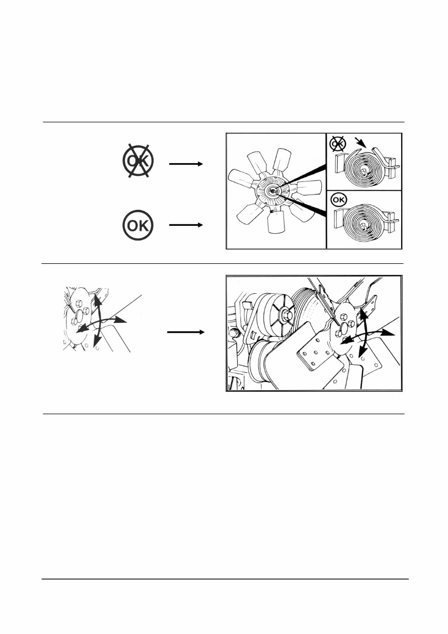
Some illustrations contain symbols to indicate an action required and an acceptable or unacceptable condition.
Unacceptable
Acceptable
Direction of Movement
(Action)
The illustrations used in the Replacement Sections are intended to show replacement procedures when the engine
is installed in a chassis. The illustration may differ from your application, but the procedure given will be the same.
A Series Troubleshooting and Repair Manual Definition of Terms 9
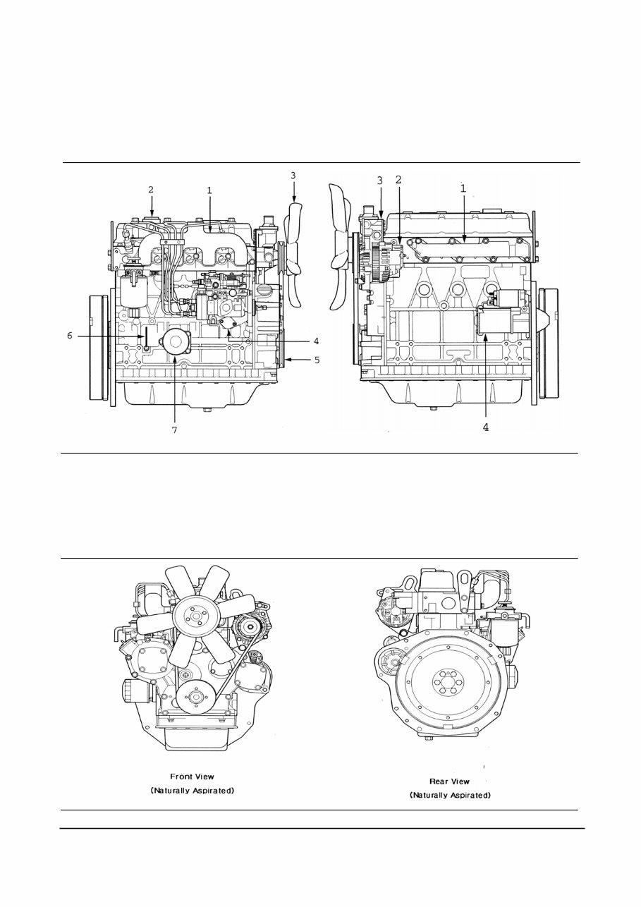
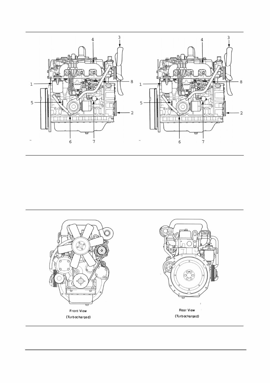
External Engine Components
The pictures which follow show the locations of the major external engine components, the filters, and other
service and maintenance points. Some external components will be at different locations for different engine
models.
Note: The pictures are only a reference to show a typical engine.
Exhaust Side [Naturally Aspirated] Intake Side [Naturally Aspirated]
1. Exhaust Manifold
2. Oil Fill Cap
3. Fan
4. Fuel Injection Pump
5. Crankshaft Pulley
6. Dip Stick
7. Oil Filter
1. Intake Manifold
2. Alternator
3. Thermostat housing
4. Starting Motor
A Series Troubleshooting and Repair Manual Definition of Terms 10
Exhaust Side [Turbocharged] Intake Side [Turbocharged]
1. Fuel Filter
2. Crankshaft Pulley
3. Cooling Fan
4. Exhaust Manifold
5. Dipstick
6. Oil Cooler
7. Fuel Injection Pump
8. Turbocharger Oil Drain Tube
1. Turbocharger
2. Alternator
3. Thermostat Housing
4. Intake Manifold
5. Starting Motor
6. Turbocharger Oil Tube
7. Oil Fill Cup
8. Air Crossover Tube
A Series Troubleshooting and Repair Manual Definition of Terms 11
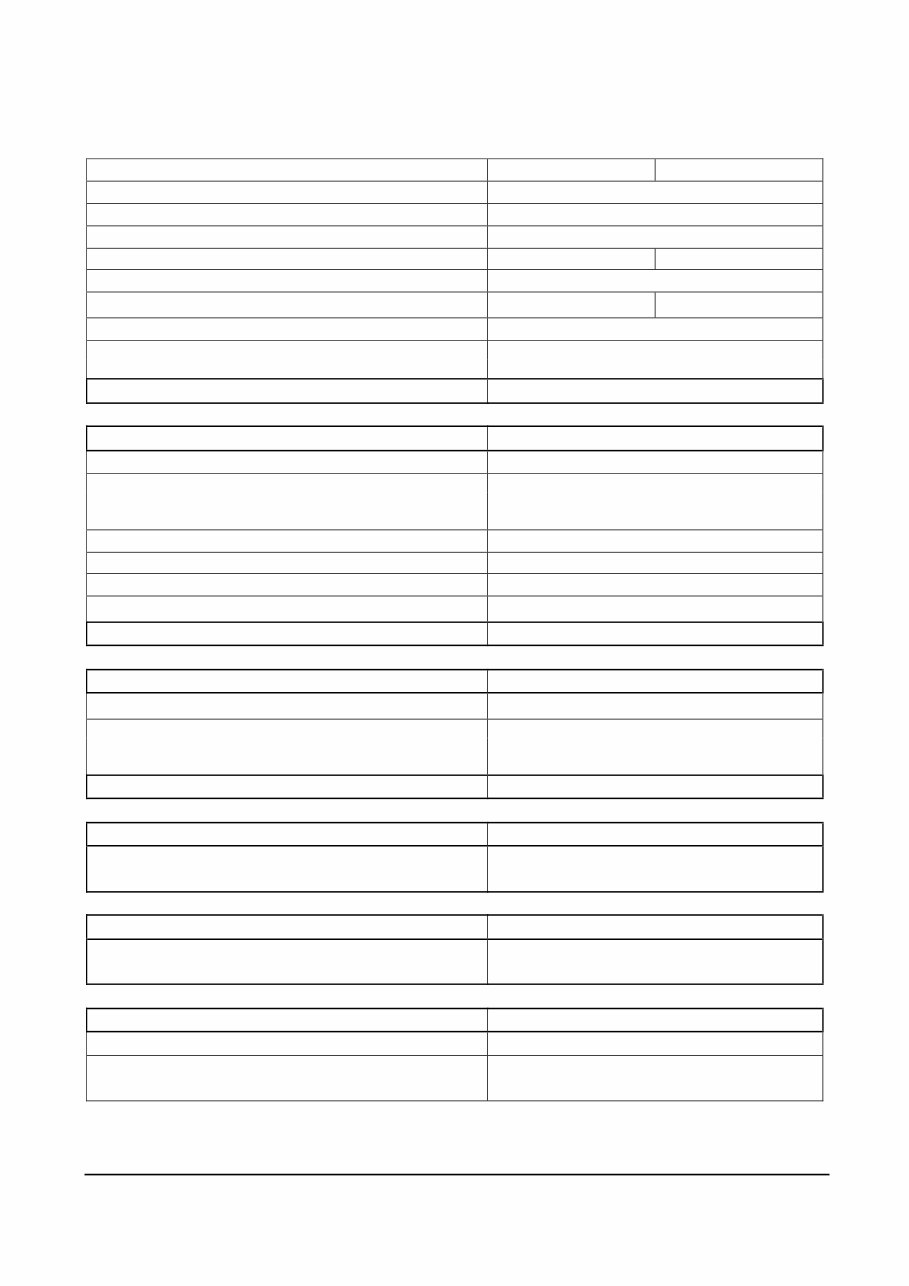
Engine Specifications
Engine Model A2000 A2300
General Engine Data Naturally Aspirated
Engine Weight(Dry) Less Flywheel and Electronics 169 kg [373 lb]
Compression Ratio 21:1
Bore [mm/inch] 84 [3.31] 88 [3.46]
Stroke [mm/inch] 94 [3.7]
Displacement [ℓ/in3] 2.08 [127] 2.29 [139]
Firing Order 1-3-4-2
Intake 0.3 mm [0.012 in]
Valve Clearance
Exhaust 0.3 mm [0.012 in]
Rotation Viewed from the Front of the Engine Clockwise
Lubrication System Naturally Aspirated
Regulating Valve Opening Pressure 290 – 390kPa [42-56 psi]
Total System 7.0 [1.85]
Lubricating Oil Capacity
[ℓ/gal]
Standard Oil
Pan Only
6.5 [1.72]
Lubricating Oil Pressure at Idle(Max. Allowable) 69 kPa [10 psi]
Lubricating Oil Pressure at Rated(Min. Allowable) 245 kPa [35 psi]
Oil Filter Differential Pressure to Open Bypass Valve 98 kPa [14 psi]
Number of liters [qt] from Low to High 2.0 ℓ [0.53 gal]
Lubrication System Forced Lubrication with Pump
Cooling System Naturally Aspirated
Coolant Capacity (Engine Only) [ℓ/gal] 3.0 [0.7]
Start 71 [160] Standard Modulating
Thermostat Range
[℃/℉]
Pulley Open 85 [185]
Cooling System Forced Lubrication with Pump
Air Induction System Naturally Aspirated
Maximum Allowable Intake Restriction at Rated
Speed and Load with Dirty Filter Element
6.23 kPa [635 mmAq]
Exhaust System Naturally Aspirated
Maximum Allowable Exhaust Restriction at Rated
Speed and Load with Dirty Filter Element
5.88 kPa [600 mmAq]
Fuel System Naturally Aspirated
Injection Pressure 150 kPa [22 psi]
Starting System
Electric starting with Starter Motor
(12 V –2.0 kW)
A Series Troubleshooting and Repair Manual Coolant System 12
Troubleshooting Logic
Engine Diagrams
A schematic of each of the major engine systems is provided at the beginning of the section of the manual devoted
to troubleshooting and repairing that particular system.
The diagrams depict flow through the various engine systems. The information and configuration of the
components illustrated in the drawings are of a general nature. Some items for specific applications and
installations may be different.
Each Section also contains a discussion regarding diagnosing malfunctions for that specific system.
Knowledge of the systems can help you troubleshoot and repair the engine.
Problem Isolation and Correction
The following Troubleshooting Logic is designed to help you organize your study of a problem and to plan a
procedure to correct it. The series of fault/logic charts given do not provide all the answers, but they should
stimulate a train of thought that will lead you to the source of the trouble.
Be sure to consider any maintenance or repair action that could have caused the problem.
If the engine surges or runs rough initially after not being used for 2 months or more, do not assume that the
engine has a malfunction. Varnish can form on the internal parts of the injection pump and the oil film can drain
from the piston rings. Operate the engine for at least 5 minutes before troubleshooting.
The basic procedure is as follows:
Study the problem thoroughly.
Relate the symptoms to your knowledge of the engine components and systems.
Double-check before beginning the disassembly.
Solve the problem by deduction starting with the easiest things.
Determine the cause of the problem and make a thorough repair.
After making corrections, operate the engine in normal conditions to verify the cause of the problem was
corrected.
A Series Troubleshooting and Repair Manual Coolant System 13
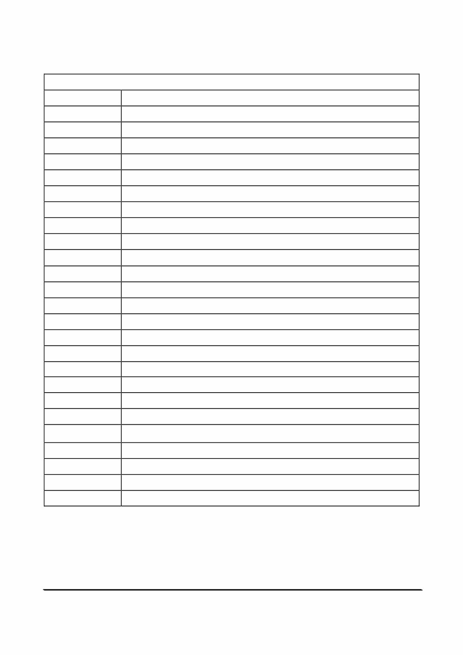
Troubleshooting Logic
Troubleshooting Logic
Page List of Symptoms
Alternator Not Charging or Insufficient Charging
Coolant Loss
Coolant Temperature Above Normal
Coolant Temperature Below Normal
Compression Knocks
Contaminated Coolant
Contaminated Lube Oil
Engine Cranks But Will Not Start – No Smoke From Exhaust
Engine Hard to Start Or Will Not Start – Smoke From Exhaust
Engine RPM Will Not Reach Rated Speed
Engine Runs Rough or Misfiring
Engine Starts But Will Not Keep Running
Engine Will Not Crank Or Cranks Slowly
Engine Will Not Shut Off
Excessive Engine Noises
Excessive Engine Smoke
Excessive Fuel Consumption
Excessive Vibration
Fuel or Oil Leaking From Exhaust Manifold
Low Power
Lube Oil Loss
Lubricating Oil Pressure Low
Lubricating Oil Pressure Too High
Rough Idle (Irregularly Firing Or Engine Shaking)
Surging (Engine Speed Change)
A Series Troubleshooting and Repair Manual Coolant System 14
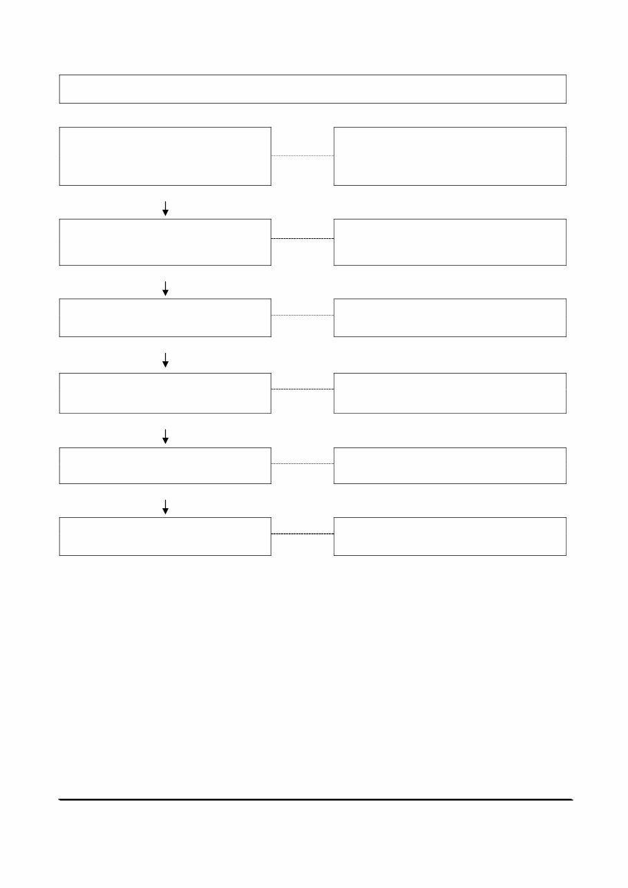
Engine Will Not Crank or Cranks Slowly
Cause Correction
Starting Motor Operating But Not
Cranking the Engine
Remove the Starting Motor and Check for
Broken Teeth on the Flywheel or Broken
Starting Motor Spring. Refer to Page 134
OK
Crankshaft Rotation Restricted
Bar the Engine to Check for Rotational
Resistance. Refer to Page 134.
OK
Starting Circuit Connections Loose
Or Corroded
Clean and Tighten Connections.
Refer to Page 133.
OK
Battery Charge Low
Check Battery Voltage.
Refer to Page 133.
OK
No Voltage to Starter Solenoid
Check Voltage to Solenoid.
Refer to Page 133.
OK
Solenoid or Starting Motor
Malfunction
Replace Starting Motor.
Refer to Page 140.
You're Reading a Preview
What's Included?
Fast Download Speeds
Online & Offline Access
Access PDF Contents & Bookmarks
Full Search Facility
Print one or all pages of your manual
$39.99
Viewed 19 Times Today


Secure transaction
What's Included?
Fast Download Speeds
Online & Offline Access
Access PDF Contents & Bookmarks
Full Search Facility
Print one or all pages of your manual
$39.99
This workshop service repair manual covers the CUMMINS A SERIES A2000 A2300 ENGINE, including the 2.08L 4-cylinder naturally aspirated A2000 engine and the 2.30L 4-cylinder naturally aspirated/turbocharged A2300 engine.
The manual includes:
- Generic symbols
- Star pattern torque sequence
- Illustrations
- External engine components
- Engine diagrams
- Coolant system
- Thermostat
- Belt tensioner-fan pulley
- Water pump-fan hub
- Fuel system
- Air in the fuel system
- Fuel system malfunction diagnosis
- Injection pump
- High pressure lines venting
- Fuel filter-fuel drain
- Air system
- Malfunctioning turbocharger
- Intake manifold
- Exhaust manifold
- Intake air restriction
- Lubricating system
- Oil cooler element and/or gasket
- Oil pump-oil pan
- Electrical system
- Starting motor
- Alternator
- Temperature sensor
- Cylinder head and valve train
- Gear housing and gear train
- Front crankshaft seal
- Camshaft, tappets and push rods
- Flywheel housing and flywheel
- Piston and rod assemblies
- Crankshaft and main bearings
- Valve train and head assembly
- Air and fuel system
- Engine removal
- Engine installation
- Engine testing
- Troubleshooting
- Special tools
This comprehensive manual is available in .PDF format and features detailed exploded views, step-by-step written procedures with pictures and diagrams, and is fully printable. It is the same manual used by technicians for engine repairs, maintenance, and servicing.


