
, Classic 5.7L Carburetor Product Installation Manual")
2007 Crusader engines 5.0L MPI, 5.7L MPI, 6.0L MPI, 8.1L MPI, 8.1L MPI (HO), Classic 5.7L Carburetor Product Installation Manual
What's Included?
Fast Download Speeds
Online & Offline Access
Access PDF Contents & Bookmarks
Full Search Facility
Print one or all pages of your manual
E N G I N E S
PRODUCT
INSTALLATION MANUAL
03/07 L510023-07 Retail Price $12.00

This Page Was
Intentionally Left
Blank

Welcome to the growing family of Crusader Marine Engines owners. We are delighted you have chosen Crusader
power for your boat and wish you many years of enjoyment.
When you chose Crusader, you selected the utmost in premium power for your boating application. Pleasurecraft
is the world’s largest manufacturer of gasoline marine inboards, and the clear-cut leader in cutting edge technology.
Over the years, we have introduced many breakthrough innovations that quickly became industry standards. No
matter which Crusader model you purchased, you can be sure it is equipped with the latest in modern technology for
added performance and durability.
READ THIS MANUAL THOROUGHLY
Before you begin the installation of your new Crusader engine, READ THIS MANUAL CAREFULLY AND
COMPLETELY. There are many new and exciting features available with your new Crusader that you may wish to
take advantage of and plan for as you begin the installation of your new Crusader engine.
Crusader Sync-N-Cruz - Every new fuel injected Crusader engine is capable of twin engine synchronization and
cruise control with the addition of the Crusader Sync-N-Cruz Kit RF152007. This kit includes a harness and control
panel which provides for a very simple installation for plug and play operation. For twin engine applications, the
Master/Slave engine harness is required.
Crusader Engines has worked closely with FW Murphy who makes available multifunction digital displays, such as
PowerView and HelmView, plus a complete line of CAN Bus Instrumentation that are completely compatible with your
new Crusader engine. The Crusader Engines’ ECM-07 engine management system outputs J1939 and NEMA 2000
protocol messages that may be compatible with other manufacturers’ multifunction display equipment. Check with
the manufacturer of the display and / or instrument you are considering, prior to purchase, for compatibility with the
Crusader ECM-07 system.
Crusader Engines has taken care to develop a complete line of adapters and boat harnesses to make your new
installation as seamless as possible. Items available include adapters for engine to existing boat harness, twin engine
Master/Slave harness, engine alarm kit, electric fuel solenoid valves, and water separating fuel filters.
Please read this manual carefully and plan ahead. There may be additional items that you may wish to replace or
upgrade as you install your new Crusader engine. If you do not understand any portion of the manual or require
additional supplies or accessories, contact your Distributor/Dealer for clarification or assistance.
The descriptions and specifications contained in this manual were in effect at the time of printing. Crusader Marine
Engines’ policy of continued improvement reserves the right to change specifications or design without notice and
without obligation.
This manual will cover the following Crusader engines:
Year Model
2007 5.0L MPI
2007 5.7L MPI
2007 6.0L MPI
2007 8.1L MPI
2007 8.1L MPI (HO)
2007 Classic 5.7L Carburetor
Part Number - L510023-07 Printed 03/07


1
L510023-07
TABLE OF CONTENTS
SECTION...................................................................................................................……................................................ Page
General Information ….....……...……...……..........................................……...……...……...………......... 3
Engine Models …..............…...…............…...……...……..............……...……...……...……...………...... 3
Crusader Accessories …..............…...……..................................……...……...……...……...………......... 3
Engine Installation Accessories …..................................................……...……...……...……...………......... 3
Installation Supplies …...................…...……...……................................……...……...……...………......... 3
Installation Drawings …...................…...…...……...…...................……...……...……...……...………........ 3
Engine and Transmission Combinations …..............….........……..……...……...……...……...………......... 4-6
Transmission Rotation …..............…...……...……...…................……...……...……...……...………....... 6-7
Gear Ratio Selection …..............….......……...……...……...............…...……...……...……...………......... 8
Propeller Shaft / Coupling …..............…...…....……...…..............……...……...……...……...………......... 8
Transmission and Propeller Rotation ….............…...……...........….……...……...……...….......………......... 8
Propeller Selection …..............…...…….........……...…...............…...……...……...……...………......... 8-11
Boat Construction …..............…...……..........……...…......................................…...……...………......... 12
Installation Requirements …...........…...……...……..........……...……...……...……...……...………......... 12
Instrumentation …..............…...…..........…...……...……............……...……...……...……...………........ 13
Twin Engine Synchronization and Speed Control (Optional) ...........................……...…….................……....... 13
Master/Slave Wiring Connection …................…...….....................……...……...……...……...………......... 14
Engine Warning Kit (Optional) …....................…..................................……...……...….......………....... 14-15
Electrical System Precautions …................…...…........................................……...……........................... 16
Engine Harness Electrical Connector Identification …........................….................…...…...……...……........ 17
Crusader Classic 5.7L Carburetor - Electrical System Precautions …....................….............……...……......... 18
Crusader Classic Installation Accessories …....................….......…...……...….............….....…...……......... 18
Crusader Classic Engine Wiring Diagram …....................….......…...……...…….........................……......... 19
Boat Adapter Harness Diagram …....................…................................…...……...……...……...……......... 20
Engine Boat Harnesses and Accessories Diagram …....................….......…...……...……...……...……......... 21
Crusader Boat Harness Wiring Diagram …....................….......…...........................……...……...……......... 22
Engine Speed Control/CAN-Bus Harness Diagram …....................….............……...……...……...……......... 23
Sync/Cruise Switch Panel Wiring Diagram …....................….................…...……...……...……...……......... 24
Crusader Boat Speed Control Harness Wiring Diagram ….............….......…...……...……...…..….……......... 25
Engine Compartment Ventilation …................…...…….........................……...……...…...……...……........ 26
Fuel Supply and Return Connections …............................................................................……...……........ 27
Fuel Inlet Restriction …..............…...…....…...……........................……...……...……...……...……......... 28
Fuel Lines …..............…...……...……...……...…….........................................….......……...……......... 28
Fuel System Pressure Check …................................................…...……...……...……...……...……......... 28
Gasoline Requirements …..............................................................................................……...……........ 29
Gasoline Containing Alcohol …..............…...…..............................……...……...……...……..................... 29
Fuel Stabilizer Recommendations for Ethanol Blended Fuel …...................................……...……...……......... 29
Fuel Filter Recommendations for Ethanol Blended Fuel …..............…...……...……...……...……...……......... 30
Exhaust System …...............................…...……....................…...……...……...……...……...……......... 31
Exhaust Risers …..............….....................……................…...……...……...……...……...……......... 31-34
Throttle/Shift Remote Control and Cables …..............................….……...……...……...……...………......... 35
Seawater Pickup Connection …..............…...……....................…...……...……...……...……...……......... 35
Seacock Size Recommendation …..............…...…...........…............……...……...……...……...……......... 35
Sea Strainer Recommendation …..............…...…...........…..........…...…...……...……...……...……......... 35
Crankcase Oil Dipstick Relocation …..............…................................……...……...……...……...……....... 35
Engine Installation …............................…...……....................…...……...……...……...……...……......... 36

2
L510023-07
SECTION...................................................................................................................……................................................ Page
Torque Specifications …........................…...……....................…...……...……...……...……...……......... 36
Preliminary Engine Alignment ….............…...…….....................…...……...……...……...……...……......... 36
Final Engine Alignment …......................…...…….....................…...................…...……...................... 37-39
Throttle/Shift Cables …..............…..............……...............…...……...……...……...……...………....... 39-43
Audio Alarm System …..............…..............…….....................…...……...……...……...……...……......... 43
Exhaust System Connection …....…..............…….........................……...……...……...……...………....... 44
Engine Harness Connection ….....................……..................…...……...……...……...……...………........ 44
Battery Connection …..............…..............……..........…............……...……...……...……...………......... 44
Master Engine Specifications ….......................……..............…...……...……...……...……...……........ 45-48
Delivery Preparation …..............…..............……......................…...……...……...……...……...……........ 49
Pre-Delivery Checklist …............…................……..................….......…...……...……...……...……......... 49
Pre-Delivery Procedure …............…........................................…...……...……...…..……...……......... 50-59
INSTALLATION DRAWINGS:
EXHAUST SYSTEM INSTALLATION GUIDELINES ...................................................................................... 60
CAPTAIN’S CHOICE INSTALLATION DRAWINGS:
5.7L BOSCH / VELVET DRIVE 72 REDUCTION .......................................................................................... 61
5.7L BOSCH / HURTH 630 8° DOWN ANGLE ............................................................................................. 62
5.7L BOSCH / HURTH 630V .................................................................................................................... 63
5.7L BOSCH / VELVET DRIVE 72 DIRECT DRIVE ...................................................................................... 64
6.0L W/4 IN. RISERS / HURTH 630 8° DOWN ANGLE ................................................................................. 65
8.1L / HURTH 630A 8° DOWN ANGLE ...................................................................................................... 66
8.1L / VELVET DRIVE 72 DIRECT DRIVE ...................................................................................................67
8.1L / VELVET DRIVE 72 REDUCTION ...................................................................................................... 68
CRUSADER XL SERIES INSTALLATION DRAWINGS:
350XL-HT WITH HURTH V-DRIVE GEAR .................................................................................................. 69
350XL-HT WITH VELVET DRIVE 5000V GEAR .........................................................................................70
350XL-HT WITH HURTH SERIES - 8° DOWN ANGLE .............................................................................. 71
350XL-HT WITH VELVET DRIVE 72 SERIES V-DRIVE ............................................................................... 72
350XL-HT WITH VELVET DRIVE 72 SERIES REDUCTION .......................................................................... 73
350XL-HT WITH VELVET DRIVE 5000 SERIES - 8° DOWN ANGLE ............................................................. 74
Crusader Engines Distributors ….......…........................................…...……...……................................... 75
Appendix A Captain’s Choice and Xli Installation Drawings …........……...……...……...……...……......... A1-A40
Appendix B XL Series Installation Drawings …......................…...……...……...……...……...…............. B1-B30
3
L510023-07
GENERAL INFORMATION
Notice to Installer
Throughout this manual, “Warnings” and “Cautions”
(accompanied by the International Hazard Symbol)
are used to alert the installer to special instructions
concerning a particular service or operation that may
be hazardous if performed incorrectly or carelessly.
Observe them carefully!
These “Safety Alerts” alone cannot eliminate the hazards
that they signal. Strict compliance to these special
instructions when performing the service, plus “common-
sense” operation, are major accident prevention
measures.
WARNING
Hazards or unsafe practices which could result in
severe personal injury or death.
CAUTION
Hazards or unsafe practices which could result in
minor personal injury or product or property damage.
IMPORTANT: Indicates information or instructions
that are necessary for proper installation and/or
operation.
Experience gained over the past several years has
shown that marine engines fitted with electronic fuel
injection (EFI) require carefully integrated fuel delivery
systems. More specifically, the fuel tank, fuel supply
and return lines, fuel filters and all their associated
valves and fittings must be considered an integral part
of any fuel injection engine package. This may require
changes in both fuel system components and/or layout
to assure compatibility and 100% customer satisfaction
with the latest EFI engines.
Any new or re-power application involving the
replacement of a non-EFI engine with an EFI engine
may require a new or modified fuel delivery system,
from the tank to the engine, for proper operation. This
installation manual has been published by Crusader
Engines to aid installers when installing the products
described herein.
It is assumed that these personnel are familiar with the
installation procedures of similar products manufactured
and marketed by Crusader Engines. That they have
been trained in the recommended installation procedures
of these products which includes the use of mechanics’
common hand tools and any recommended tools from
other manufacturers.
We could not possibly know of and advise the marine
trade of all conceivable procedures by which an
installation might be performed and of the possible
hazards and/or results of each method. We have not
undertaken any such wide evaluation. Therefore,
anyone who uses an installation procedure and/or tool,
which is not recommended by the manufacturer, first
must completely satisfy himself that neither his nor the
product’s safety will be endangered by the installation
procedure selected.
All information, illustrations and specifications contained
in this manual are based on the latest product
information available at the time of publication.
ENGINE MODELS
This manual gives installation guidelines for the following
engine models.
MP 5.0L / MP 5.7L
MP 6.0L
MP 8.1L STD
MP 8.1L HO
Carb. 5.7L
CRUSADER ACCESSORIES
Instrument panels, wiring harnesses, propeller shaft
couplers, etc. are available for this product. Contact
your Crusader Engines Distributor or Crusader Engines
Sales Department for a listing of these options. A list of
Distributors is provided at the end of this manual.
ENGINE INSTALLATION ACCESSORIES
Electric Fuel Solenoid Valve P/N 23532
Solenoid Valve Power Harness P/N 98452
Water Separating Fuel Filter Kit P/N RK080033
Check Engine Lamp / Alarm Kit P/N RK179008
Crusader Sync-N-Cruz Kit P/N RF152007
Master / Slave Wire Harness: P/N RA121072C
Adapter - Engine to Boat Harness see page 20
Boat to Engine Harness see page 21
INSTALLATION SUPPLIES
Marine Lubricant
Liquid Neoprene
Perfect Seal or equivalent
Loctite PST Pipe Sealant or equivalent
Mount Adjustment Tool - P/N 22165
INSTALLATION DRAWINGS
Installation drawings are at the back of this manual.
These and archive installation drawings, are also
available at crusaderengines.com
4
L510023-07
ENGINE AND TRANSMISSION
COMBINATIONS
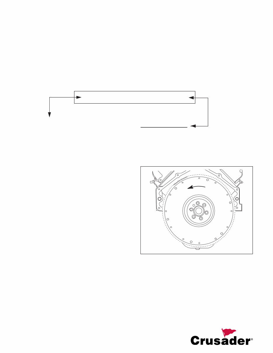
Engine Rotation:
Engine rotation is indicated by the model number on the
engine serial number plate. Engine rotation is described
by flywheel rotation viewing from the rear of the engine
(transmission end) looking forward to the water pump
end. Refer to the Crusader Model Identification/Advisory
information below.
Figure 1 Flywheel Showing LH Rotation
CRUSADER MODEL IDENTIFICATION /
ADVISORY
MODEL 23 - 6 0 0 V - 0 1 SERIAL 670000
*SERIAL NUMBER I.D.*
1
st
DIGIT INDICATES DECADE ENGINE WAS
MANUFACTURED ( 5 = 1990, 6 = 2000, 7 = 2010 )
2
nd
DIGIT INDICATES YEAR ENGINE WAS
MANUFACTURED.
1
st
- 2
nd
Space: MANUFACTURING CODE
3
rd -
5
th
Space: ENGINE CODE
810 = 8.1L (496 CID LH MPI) (GM)
811 = 8.1L (496 CID LH H.O. MPI) (GM)
600 = 6.0L (364 CID LH MPI) (GM)
570 = 5.7L (350 CID LH MPI) (GM)
571 = 5.7L (350 CID RH MPI) (GM)
572 = 5.7L (350 CID LH Carburetor) (GM)
573 = 5.7L (350 CID RH Carburetor) (GM)
500 = 5.0L (305 CID LH MPI) (GM)
501 = 5.0L (305 CID RH MPI) (GM)
502 = 5.0L (305 CID LH Carburetor) (GM)
503 = 5.0L (305 CID RH Carburetor) (GM)
6
th
Space: DRIVE CONFIGURATION
blank - Direct Drive
V - V-Drive
7
th -
8
th
Space: SPECIFICATION CODE
5
L510023-07
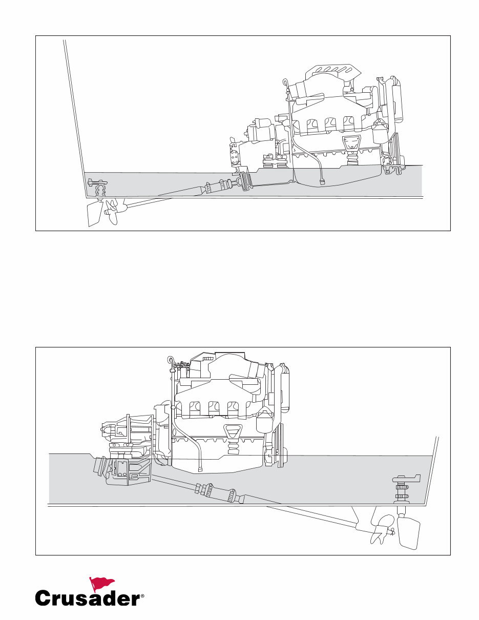
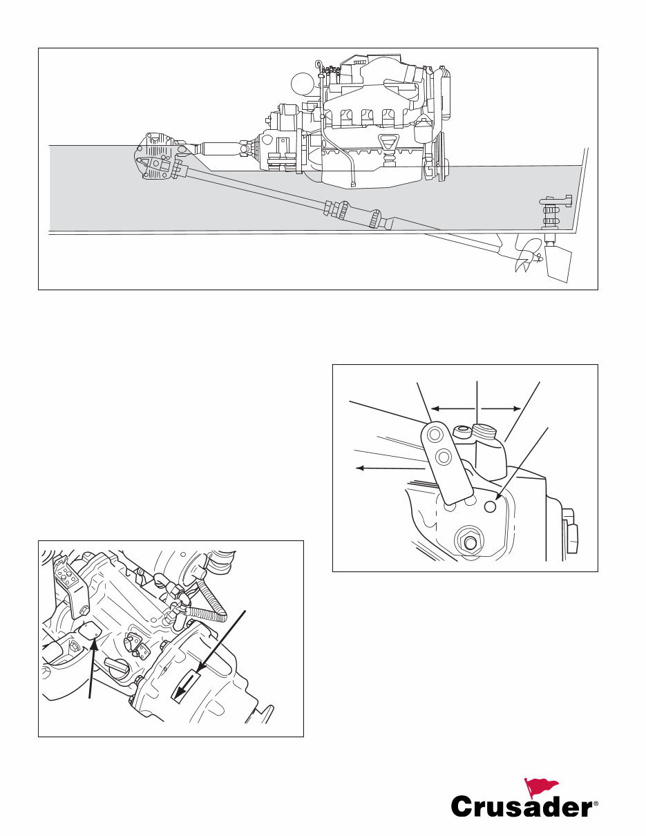
Figure 2 Engine Applications - Typical 8 Degree Down Angle Transmission
Figure 3 Engine Applications - Typical V-Drive Transmission
6
L510023-07
TRANSMISSION ROTATION
Velvet Drive In-Line and V-Drive
Transmission gear ratio (in forward gear) is marked
on the transmission identification plate. Transmission
output shaft rotation is indicated on a decal on the
transmission case.
IMPORTANT: Use of proper rotation propeller,
indicated by the output flange rotation decal, is
critical as operating the transmission in Reverse to
move the boat forward WILL CAUSE transmission
failure. The transmission MUST BE operated in
forward gear only to propel the boat forward.
Figure 5 Standard Velvet Drive Identification Plate and
Propshaft Rotation
Figure 6 Shift Lever Positions - Standard Velvet Drive
PROP SHAFT
ROTATION
DECAL
IDENTIFICATION
TAG
TOWARD
FLYWHEEL
FOR
FORWARD
POPPET
BALL
F N R
Figure 4 Engine Applications - Typical Remote V-Drive Transmission
You're Reading a Preview
What's Included?
Fast Download Speeds
Online & Offline Access
Access PDF Contents & Bookmarks
Full Search Facility
Print one or all pages of your manual
$26.99
Viewed 33 Times Today


Secure transaction
What's Included?
Fast Download Speeds
Online & Offline Access
Access PDF Contents & Bookmarks
Full Search Facility
Print one or all pages of your manual
$26.99
This manual provides access to installation guides for 2007 Crusader engines, such as the 5.0L MPI, 5.7L MPI, 6.0L MPI, 8.1L MPI, and the 8.1L MPI (HO) with the Classic 5.7L Carburetor. It contains comprehensive instructions and illustrations, making it suitable for both professional mechanics and DIY enthusiasts for servicing, troubleshooting, and overhauling engines.
Key inclusions:
- Specifications for 2007 Crusader Engines
- Proper Installation Instructions
- Step-by-step Troubleshooting & Overhauling Guidance
- Illustrations for Overhaul & Repair Operations
This manual is accessible online and can be instantly downloaded upon purchase.


