

X30569A IO-550 Parts Manual
What's Included?
Fast Download Speeds
Online & Offline Access
Access PDF Contents & Bookmarks
Full Search Facility
Print one or all pages of your manual
CAT LOG
10-550-
-B
-c
-G
Form X30569A
© 1989 Teledyne industries, Inc.
September 1989
CURRENT STATUS OF PAGES AS OF:
SEPTEMBER 1989
THE ORIGINAL DATE OF THIS PUBLICATION IS SEPTEMBER 1989
INSERT LATEST PAGES DESTROY SUPERSEDED PAGES
MODELS: 10-550 FORM X30569A
PAGE STATUS
ALL SEPTEMBER 1989
PAGE STATUS PAGE STATUS PAGE STATUS
li
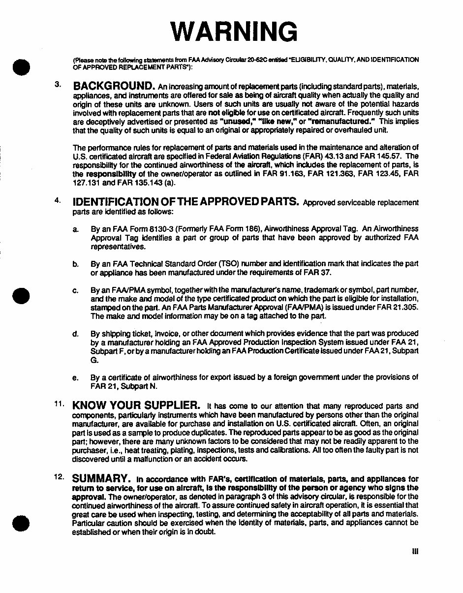
WARNING
(Please note the following statements from FAA Advisory Circular 20-620 enlatledEUGIBIU'TY, OUAU1Y, AND IDE NTIFICATION
OF APPROVED REPLACEMENT PARTS-):
3.BACKGROUND. An increasing amount of replacement parts (including standard parts), materials,
appliances, and instruments are offered for sale as being of aircraft quality when actually the quality and
origin of these units are unknown. Users of such units are usually niot aware of the potential hazards
involved with replacement parts that are not eligible for use on certificated aircraft. Frequently such units
are deceptively advertised or presented as "unused," "like new," or "remanufactured." This implies
that the quality of such units is equal to an original or appropriately repaired or overhauled unit.
The performance rules for replacement of parts and materials used in the maintenance and alteration of
U.S. certificated aircraft are specified in Federal Aviation Regulations (FAR) 43.13 and FAR 145.57. The
responsibility for the continued airworthiness of the aircraft, which includes the replacement of parts, is
the responsibility of the owner/operator as outlined in FAR 91.163, FAR 121.363, FAR 123.45, FAR
127.131 and FAR 135.143 (a).
4. IDENTIFICATION OF THE APPROVED PARTS. Approved serviceable replacement
parts are identified as follows:
a. By an FAA Form 81 30-3 (Formerly FAA Form 186), Airworthiness Approval Tag. An Airworthiness
Approval Tag identifies a part or group of parts that have been approved by authorized FAA
representatives.
b. By an FAA Technical Standard Order (TSO) number and identification mark that indicates the part
or appliance has been manufactured under the requirements of FAR 37.
c. By an FAA/PMA symbol, together with the manufacturer's name, trademark or symbol, part number,
and the make and model of the type certificated product on which the part is eligible for installation,
stamped on the part. An FAA Parts Manufacturer Approval (FANtPMA) is issued under FAR 21.305.
The make and model information may be on a tag attached to the part.
d. By shipping t icket, invoice, or other document which provides evidence that the part was produced
by a manufacturer holding an FAA Approved Production Inspection System issued under FAA 21,
Subpart F, orby a manufacturer holding an FAA Production Certificate issued under FAA 21, Subpart
G.
e. By a certificate of airworthiness for export issued by a foreign government under the provisions of
FAR 21, Subpart N.
1.KNOW YOUR SUPPLIER. It has come to our attention that many reproduced parts and
components, particularly instruments which have been manufactured by persons other than the original
manufacturer, are available for purchase and installation on U.S. certificated aircraft. Often, an original
part is used as a sample to produce duplicates. The reproduced parts appear to be as good as the original
part; however, there are many unknown factors to be considered that may niot be readily apparent to the
purchaser, i.e., heat treating, plating, inspections, tests and calibrations. All too often the faulty part is not
discovered until a malfunction or an accident occurs.
12. SUMMARY. in accrdance with FAR's, certification of materials, parts, and appliances for
return to service, for use on aIrcraft Is the responsIbIlIty of the person or agency who signs the
approval. The owner/operator, as denoted in paragraph 3 of this advisory circular, is responsible for the
continued airworthiness of the aircraft. To assure continued safety in aircraft operation, it is essential that
great care be used when inspecting, testing, and determining the acceptability of all parts and materials.
Particular caution should be exercised when the identity of materials, parts, and appliances cannot be
established or when their origin is in doubt.
III
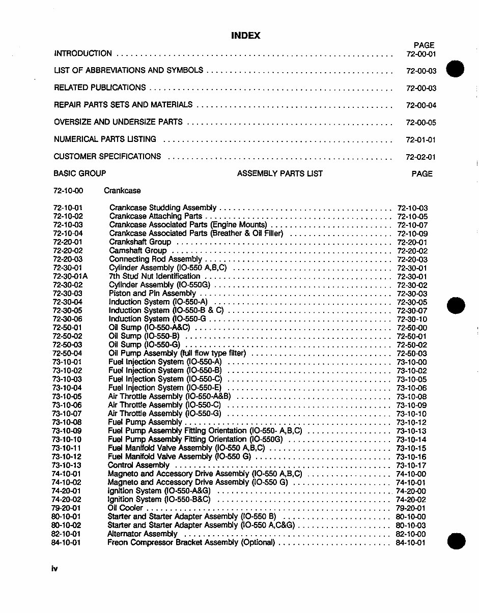
INDEX
PAGE
INTRODUCTION...............................72-00-01
UIST OF ABBREVIATIONS AND SYMBOLS ..................... 72-00-03
RELATED PUBUICATIONS ........................... 72-00-03
REPAIR PARTS SETS AND MATERIALS ...................... 72-00-04
OVERSIZE AND UNDERSIZE PARTS ....................... 72-00-05
NUMERICAL PARTS UISTING..........................72-01-01
CUSTOMER SPECIFICATIONS ......................... 72-02-01
BASIC GROUP ASSEMBLY PARTS LIST PAGE
72-10-00 Crankcase
72-10-01 Crankcase Studding Assembly....................72-10-03
72-10-02 Crankcase Attaching Parts ..................... 72-10-05
72-10-03 Crankcase Associated Parts (Engine Mounts) .............. 72-10-07
72-10-04 Crankcase Associated Parts (Breather & Oil Filler) ............ 72-10-09
72-20-01 Crankshaft Group ........................ 72-20-01
72-20-02 Camshaft Group.........................72-20-02
72-20-03 Connecting Rod Assembly ..................... 72-20-03
72-30-01 Cylinder Assembly (10-550 A,B,C) .................. 72-30-01
72-30-01 A 7th Stud Nut Identification ..................... 72-30-01
72-30-02 Cylinder Assembly (IO-550G) .................... 72-30-02
72-30-03 Piston and Pin Assembly ...................... 72-30-03
72-30-04 Induction System (10-550-A) .................... 72-30-05
72-30-05 Induction System (10-550-B & C)...................72-30-07
72-30-06 Induction System (IO-550-G.....................72-30-10
72-50-01 Oil Sump (IO-550-A&C) ...................... 72-50-00
72-50-02 Oil Sump (10-550-B) ....................... 72-50-01
72-50-03 Oil Sump (10-550-G) ....................... 72-50-02
72-50-04 Oil Pump Assembly (full flow type filter) ................ 72-50-03
73-10-01 Fuel Injection System (10-550-A)...................73-10-00
73-10-02 Fuel Injection System (10-550-B)...................73-10-02
73-10-03 Fuel Injection System (10-550-C)...................73-10-05
73-10-04 Fuel Injection System (10-550-E)...................73-10-06
73-10-05 Air Throttle Assembly (10-550-A&B)..................73-10-08
73-10-06 Air Throttle Assembly (10-550-C)...................73-10-09
73-10-07 Air Throttle Assembly (10-550-G)...................73-10-10
73-10-08 Fuel Pump Assembly. 73-10-12
73-10-09 Fuel Pump Assembly Fittn~g Ori'e'ntation' ('I0'-5'50- A',B',C')............73-10-13
73-10-10 Fuel Pump Assembly Fitting Orientation (lO-550G) ............ 73-10-14
73-10-11 Fuel Manifold Valve Assembly (10-550 AB,C) .............. 73-10-15
73-10-12 Fuel Manifold Valve Assembly (10-550 G)................73-10-16
73-10-13 Control Assembly ............ .......... 73-10-17
74-10-01 Magneto and Accessory Drive Assembly (10-550 AB.C..........74-10-00
74-10-02 Magneto and Accessory Drive Assembly (10-550 G)............74-10-01
74-20-01 Ignition System (10-550-A&G) .................... 74-20-00
74-20-02 Ignition System (10-550-B&C)....................74-20-02
79-20-01 Oil Cooler ........................... 79-20-01
80-10-01 Starter and Starter Adapter Assembly (10-550 B).............80-10o-00
80-10-02 Starter and Starter Adapter Assembly (10-550 AC&G) .80.........S-10-03
82-10-01 Alternator Assembly..........82-10-00
84-10-01 Freon Compressor Bracket Assembly (Optional) ................ 84-10-01
.IV
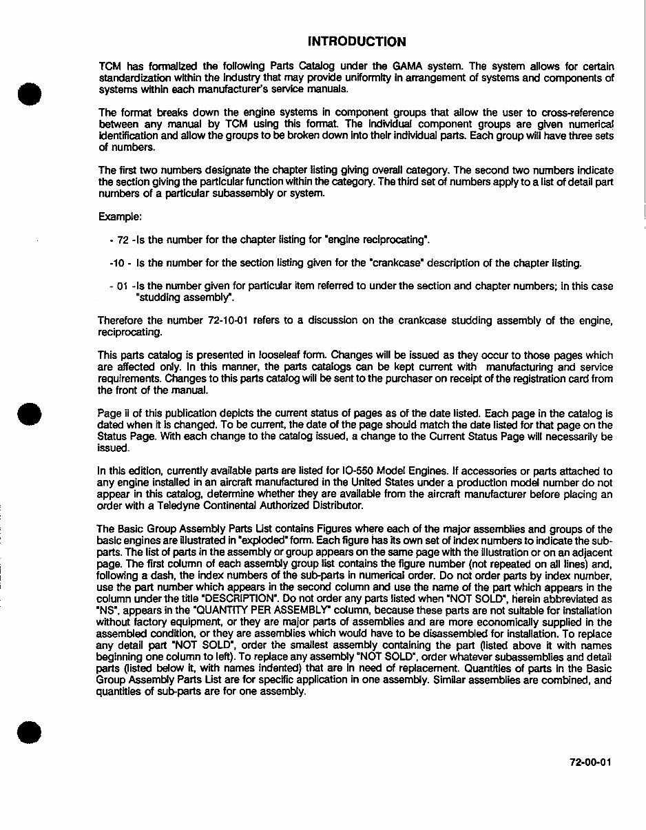
INTRODUCTION
TCM has formalized the following Parts Catalog under the GAMA system. The system allows for certain
standardization within the industry that may provide uniformity in arrangement of systems and components of
systems within each manufacturer's service manuals.
The format breaks down the engine systems in component groups that allow the user to cross-reference
between any manual by TCM using this format. The indivdual component groups are given numerical
Identification and allow the groups to be broken down into their indivdual parts. Each group will have three sets
of numbers.
The first two numbers designate the chapter listing givng overall category. The second two numbers indicate
the section givng the particular function within the category. The third set of numbers apply to a list of detail part
numbers of a particular subassembly or system.
Example:
- 72 - Is the number for the chapter listing for 'engine reciprocating'.
-10 - Is the number for the section listing given for the "crankcase" description of the chapter listing.
- 01 -is the number given for particular item referred to under the section and chapter numbers; in this case
"studding assembly".
Therefore the number 72-10-01 refers to a discussion on the crankcase studding assembly of the engine,
reciprocating.
This parts catalog is presented in looseleaf form. Changes will be issued as they occur to those pages which
are affected only. In this manner, the parts catalogs can be kept current with manufacturing and service
requirements. Changes to this parts catalog will be sent to the purchaser on receipt of the registration card from
the front of the manual.
Page ii of this publication depicts the current status of pages as of the date listed. Each page in the catalog is
dated when it is changed. To be current, the date of the page should match the date listed for that page on the
Status Page. With each change to the catalog issued, a change to the Current Status Page will necessarily be
issued.
In this edition, currently available parts are listed for 10-550 Model Engines. If accessories or parts attached to
any engine installed in an aircraft manufactured in the United States under a production model number do not
appear in this catalog, determine whether they are available from the aircraft manufacturer before placing an
order with a Teledyne Continental Authorized Distributor.
The Basic Group Assembly Parts Uist contains Figures where each of the major assemblies and groups of the
basic engines are illustrated in "exploded" form. Each figure has its own set of index numbers to indicate the sub-
parts. The list of parts in the assembly or group appears on the same page with the illustration or on an adjacent
page. The first column of each assembly group list contains the figure number (not repeated on all lines) and,
following a dash, the index numbers of the sub-parts in numerical order. Do not order parts by index number,
use the part number which appears in the second column and use the name of the part which appears in the
column under the title "DESCRIPTION". Do not order any parts listed when 'NOT SOLD", herein abbreviated as
'NS", appears in the "QUANTITY PER ASSEMBLY" column, because these parts are not suitable for installation
without factory equipment, or they are major parts of assemblies and are more economically supplied in the
assembled condition, or they are assemblies which would have to be disassembled for installation. To replace
any detail part "NOT SOLD", order the smallest assembly containing the part (listed above It with names
beginning one column to left). To replace any assembly 'NOT SOLD", order whatever subassemblies and detail
parts (listed below it, with names Indented) that are in need of replacement. Quantities of parts In the Basic
Group Assembly Parts List are for specific application in one assembly. Similar assemblies are combined, and
quantities of sub-parts are for one assembly.
72-00-01
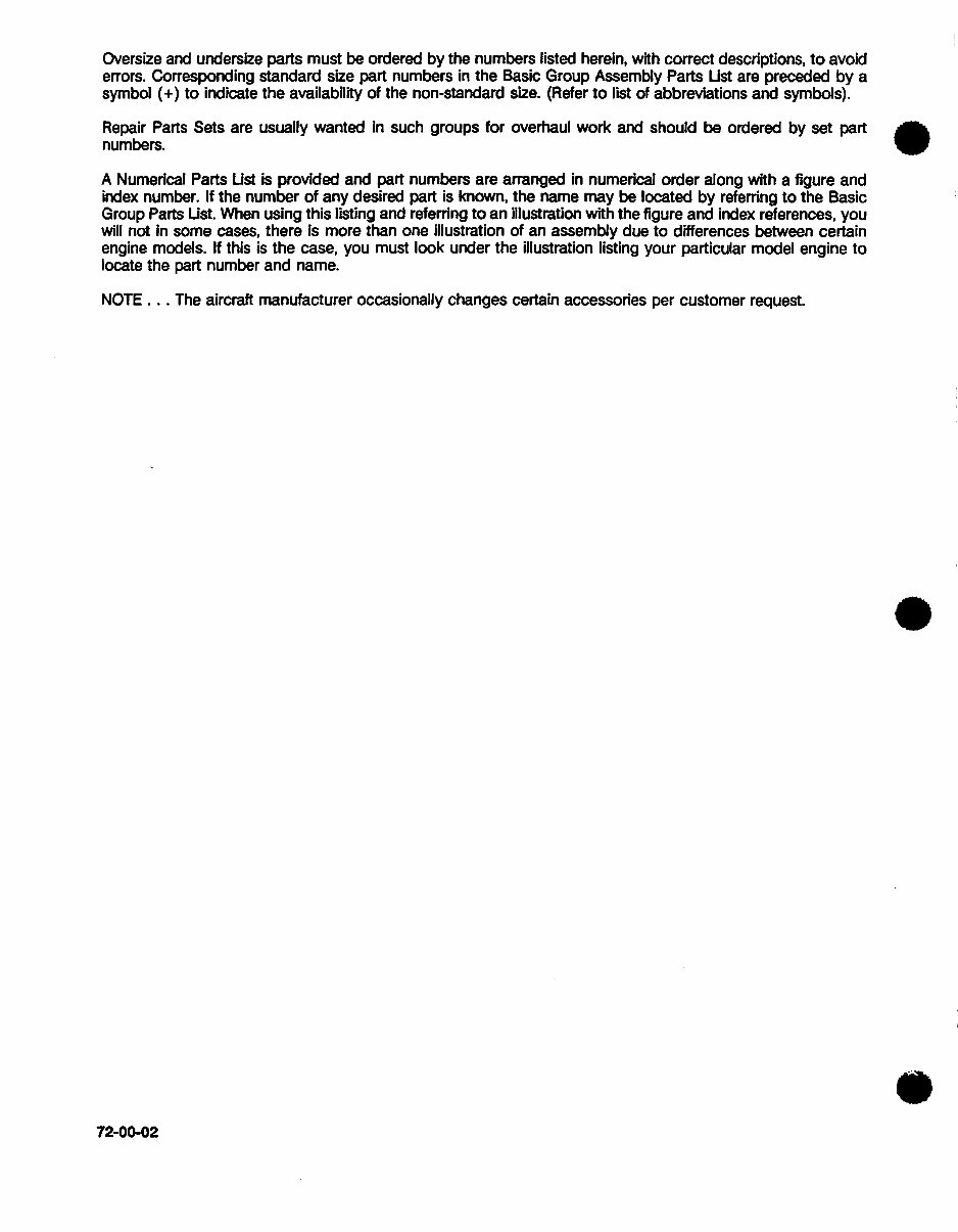
Oversize and undersize parts must be ordered by the numbers listed herein, with correct descriptions, to avoid
errors. Corresponding standard size part numbers in the Basic Group Assembly Parts Ust are preceded by a
symbol (+) to indicate the availability of the non-standard size. (Refer to list of abbreviations and symbols).
Repair Parts Sets are usually wanted in such groups for overhaul work and should be ordered by set part
numbers.
A Numerical Parts Ust is provided and part numbers are arranged in numerical order along with a figure and
index number. If the number of any desired part is known, the name may be located by referring to the Basic
Group Parts Ust. When using this listing and referring to an illustration with the figure and index references, you
will not In some cases, there Is more than one illustration of an assembly due to differences between certain
engine models. If this is the case, you must look under the illustration listing your particular model engine to
locate the part number and name.
NOTE ... The aircraft manufacturer occasionally changes certain accessories per customer request.
72-00-02
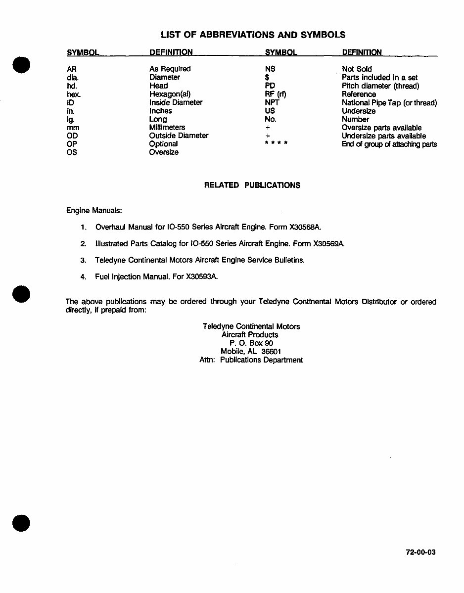
LIST OF ABBREVIATIONS AND SYMBOLS
nlFFwimTIAnbJ QvupnI
As Required
Diameter
Head
Hexagon(aI)
Inside Diameter
Inches
Long
Millimeters
Outside Diameter
Optional
Oversize
NS
PD
RF (rt)
NPT
us
No.
Not Sold
Parts Included in a set
Pitch diameter (thread)
Reference
National Pipe Tap (or thread)
Undersize
Number
Oversize parts available
Undersize parts available
End of group of attaching parts
RELATED PUBLICATIONS
Engine Manuals:
1. Overhaul Manual for 10-550 Series Aircraft Engine. Form X30568A.
2. Illustrated Parts Catalog for 10-550 Series Aircraft Engine. Form X30569A.
3. Teledyne Continental Motors Aircraft Engine Service Bulletins.
4. Fuel Injection Manual. For X30593A.
The above publications may be ordered through your Teledyne Continental Motors Distributor or ordered
directly, if prepaid from:
Teledyne Continental Motors
Aircraft Products
P. 0. Box 90
Mobile, AL 36601
Attn: Publications Department
72-00-03
aVURanE
AR
dia.
hd.
hex.
ID
in.
1g.
mm
OD
OP
Os
niwFkmrAN
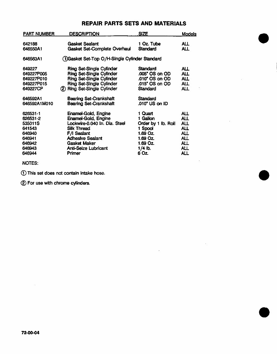
REPAIR PARTS SETS AND MATERIALS
PAPT Mil IUARPQ
642188
646550A1
646563A1
flQfQ1RPTIAM
Gasket Sealant
Gasket Set-Complete Overhail
(jGasket Set-Top 0/H-Single Cylinder Standard
649227
649227P005
649227P01 0
649227P01 5
649227CP
646592A1
646592A1 M010
Ring Set-Single Cylinder
Ring Set-Single Cylinder
Ring Set-Single Cylinder
Ring Set-Single Cylinder
(9) Ring Set-Single Cylinder
Bearing Set-Crankshaft
Bearing Set-Crankshaft
Standard
.005 OS on OD
.01060 on OD
.015' 05 on OD
Standard
Standard
.010m US on ID
626531-1
626531-2
53501 1S
641543
646940
646941
6469-42
646943
646944
Enamel-Gold, Engine
Enamel-Gold, Engine
Lockwlre-0.040 In. Dia. Steel
Silk Thread
F/I Sealant
Adhesive Sealant
Gasket Maker
Anti-Seize Lubricant
Primer
1 Quart
1 Gallon
Order by 1 lb. Roll
1 spool
1.69 Oz.
1.69 Oz.
1.69 Oz.
1/4 lb.
6 Oz
NOTES:
(J) This set does not contain intake hose.
©For use with chrome cylinders.
72-00-04
-Ql7
1 Oz. Tube
Standard
IAAn.'eJc,
ALL
ALL
ALL
ALL
ALL
ALL
ALL
ALL
ALL
ALL
ALL
ALL
ALL
ALL
ALL
ALL
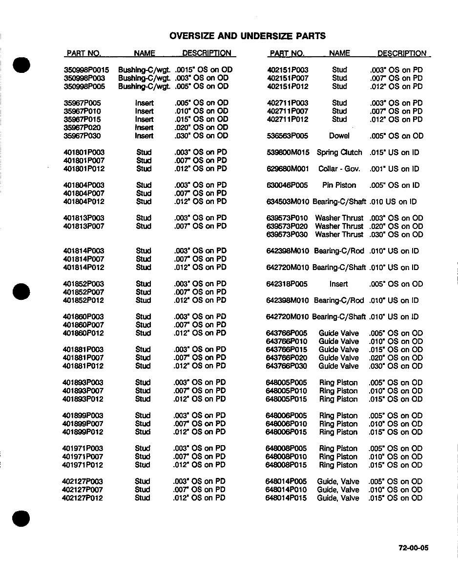
OVERSIZE AND UNDERSIZE PARTS
DESCRIPTION PART NO. NAME DESCRIPTION
350998P001 5
350998P003
350998P005
35967P005
35967P01 0
35967P01 5
35967P020
35967P030
401801 P003
401801 P007
4018011P012
401 804P003
401 804P007
401804P012
401813P003
401813P007
401814P003
40181 4P007
401814P012
401 852P003
401 852P007
401852P012
401 860P003
401 860P007
401860P012
401881 P003
401881 P007
401881 P012
401 893P003
401893P007
401893P012
401 8991P003
401 899P007
401899P012
401971 P003
401971 P007
401971 P012
4021 27P003
4021 27P007
4021 27P01 2
Bushing-C/wgt.
Bushing-C/wgt.
Bushing-C/wgt.
Insert
Insert
Insert
Insert
Insert
Stu
SWu
Stud
Stud
Stud
Stud
Stud
Stud
Stud
Stud
Stud
Stud
Stud
Stud
Stud
Stud
Stud
Stud
Stud
Stud
Stud
Stud
Stud
Stud
Stud
Stud
Stud
Stud
Stud
Stud
Stud
Stud
.001 5' 0S on OD
.003" 0S on OD
.005" 0S on OD
.005" 05 on OD
.010" OS on OD
.015* OS on OD
.020" 0S on OD
.030" 0S on OD
.003" OS on PD
.007r 0S on PD)
.01 2" 05 on PD
.003" 0S on PD
.007" 05 on PD)
.01 2' OS on PD
.003" OS on PD
.007" 05 on PD
.003" OS on PD
.007" 0S on PD
.012" OS on PD
.003" 0S on PD
.007" OS on PD
.01 2" 05 on PD
.003" 05 on PD)
.007" OS on PD
.012" 0S on PD
.003" OS on PD)
.007" OS on PD
.012" 05 on PD
.003" OS on PD
.007" OS on PD
.012' 05 on PD
.003" 05 on PD
.007" 05 on PD
.01 2" 05 on PD)
.003" 05 on PD
.007" 05 on PD)
.012" OS on PD
.003" 05 on PD)
.007" 0S on PD
.012" 0S on PD
402151 P003
402151 P007
402151 P012
402711 P003
402711 P007
40271 1PO12
536563P005
539800M01 5
629680M001
630046P005
634503M01 0
639573P01 0
639573P020
639573P030
642398M01 0
642720M010
64231 8P005
642398M01 0
642720M01 0
6437661P005
643766P01 0
643766P01 5
643766P020
643766P030
648005P005
648005P*01 0
648005P01 5
648006P005
648006P01 0
648006P01 5
648008P005
648008P01 0
648008P01 5
64801 4P005
64801 4P010
64801 4P015
Stud
Stud
Stud
Stud
Stud
Stud
Dowel
Spring Clutch
Collar - Gov.
Pin Piston
Bearing-C/Shaft
Washer Thrust
Washer Thrust
Washer Thrust
Bearing-C/Rod
Bearing-C/Shaft
Insert
Bearing-C/Rod
Bearing-C/Shaft
Guide Valve
Guide Valve
Guide Valve
Guide Valve
Guide Valve
Ring Piston
Ring Piston
Ring Piston
Ring Piston
Ring Piston
Ring Piston
Ring Piston
Ring Piston
Ring Piston
Guide, Valve
Guide, Valve
Guide, Valve
.003" 05 on PD
.007" OS on PD
.012" 05 on PD
.003" 0S on PD
.007" 05 on PD
.01 2" 0S on PD
.005" 05 on OD
.015" US on ID
.001" US on ID
.005" OS on ID
.010 US on ID
.003" OS on 0D
.020" 05 on 00
.030" 0S on O0
.010" US on ID
.010" US on ID
.005" OS on 00
.010" US on ID
.010" US on ID
.005" OS on 00
.010" 0S on 00
.015" OS on OD
.020" OS on OD
.030" OS on 00
.005" 0S on 00
.010" OS on OD
.015" 05 on OD
.005" 05 on 00
.010 05 O on 0D
.015" OS on 00
.005" OS on OD
.010"' OS on 00
.015" OS on 00
.005" 0S on 00
.010* OS on 00
.015" OS on 00
72-00-05
PART NO. NAME
PART NO.
NAME
DESCRIPTION
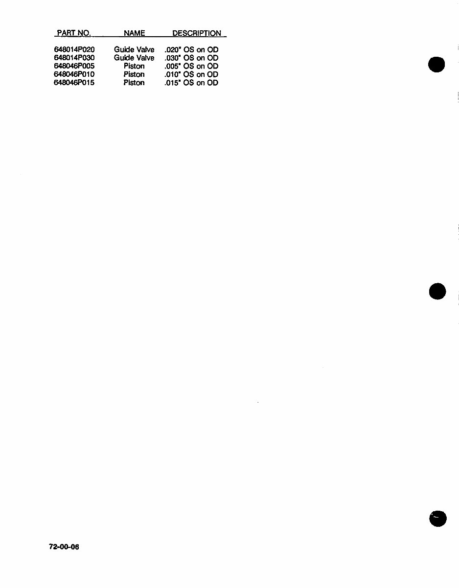
64801 4P020
64801 4P030
648046P005
648046P01 0
648046P01 5
Guide Valve
Guide Valve
Piston
Piston
Piston
.020' OS on OD
.030' OS on OD
.0O5' OS on OD
.010m OS on 00
.015' OS on OD
72-00-06
PART NO. NAME DESCRIPTION
You're Reading a Preview
What's Included?
Fast Download Speeds
Online & Offline Access
Access PDF Contents & Bookmarks
Full Search Facility
Print one or all pages of your manual
$40.99
Viewed 14 Times Today


Secure transaction
What's Included?
Fast Download Speeds
Online & Offline Access
Access PDF Contents & Bookmarks
Full Search Facility
Print one or all pages of your manual
$40.99
The X30569A IO-550 Parts Manual is a comprehensive guide covering the A, B, C, and G series. With 83 pages of detailed information, this manual is an invaluable resource for professional mechanics and DIY enthusiasts alike.


