

Continental Aircraft Engines O200-C75-C85-C90 Parts Manual
What's Included?
Fast Download Speeds
Offline Viewing
Access Contents & Bookmarks
Full Search Facility
Print one or all pages of your manual
ILLUSTRATED PARTS CATALOG
FOR
C-75, C-85, C-90 & 0-200
AIRCRAFT ENGINES
FORM X30011A
FAA APPROVED
FEBRUARY 1981
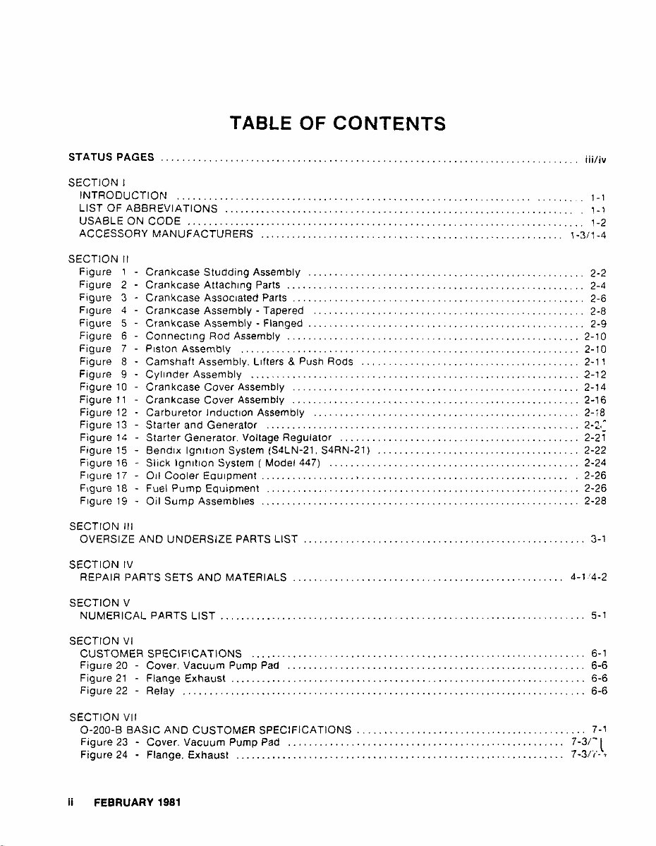
TABLE OF CONTENTS
STATUS PAGES ............. , ........................................................... . jjj/iv
• SECTION I, ._
INTRODUCTION .............. ................. ::.:":: •. :.-: .......... ..... :"'c·:1'M:.:. 1-1
LIST OF ABBREViATIONS .................................................................. 1-1
USABLE ON CODE ........................................................................... 1-2
ACCESSORY MANUFACTURERS ......................................................... 1-3/1-4
SECTION II
Figure 1
Figure 2
Figure 3
Figure 4
Figure 5
Figure 6
Figure 7
Figure 8
Figure 9
Figure 10
Figure 11
Figure 12
Figure 13
Figure 14
Figure 15
Figure 16
Figure 17
Figure 18
Figure 19
SECTION III
Crankcase Studding Assembly .................................................... 2-2
Crankcase Attaching Parts ........................................................ 2-4
Crankcase ASSOCiated Parts ....................................................... 2-6
Crankcase Assembly - Tapered ................................................... 2-8
Crankcase Assembly - Flanged .................................. " ................ 2-9
Connecting Rod Assembly ....................................................... 2-10
Piston Assembly ................................................................ 2-10
Camshaft Assembly. Lifters & Push Rods ......................................... 2-11
Cylinder Assembly .............................................................. .2-12
Crankcase Cover Assembly ...................................................... 2-14
Crankcase Cover Assembly ..................................................... 2-16
Carburetor Induction Assembly .................................................. 2-,8
Starter and Generator .............................. , ............................
Starter Generator. Voltage Regulator ............................................. 2-21
Bendix IgnitIOn System (S4LN-21. S4RN-21) ...................................... 2-22
Slick Ignition System ( Model 447) ............................................... 2-24
011 Cooler Equipment .. " .............. • ........................ , ..... , . . . . . . .. . 2-26
Fuel Pump Equipment ........................................................... 2-26
Oil Sump Assemblies ............................................................ 2-28
OVERSIZE AND UNDERSIZE PARTS LIST ..................................................... 3-1
SECTION IV
REPAIR PARTS SETS AND MATERIALS ................................................... 4-1/4·2
SECTION V
NUMERICAL PARTS LIST ..................................................................... 5·1
SECTION VI
CUSTOMER SPECIFICATIONS
Figure 20
Figure 21
Figure 22
SECTION VII
Cover. Vacuum Pump Pad ....................................................... .
Flange Exhaust .................................................................. .
Relay ........................................................................ .
6-1
6-6
6-6
6-6
0-200-B BASIC AND CUSTOMER SPECiFiCATIONS ........................................... 7-1
Figure 23 - Cover. Vacuum Pump Pad .................................................... 7-3/]
Figure 24 - Flange. Exhaust .............................................................. 7-3/(·,·
Ii FEBRUARY 1981
/
rCURRENT STATUS OF PAGES AS OF
FEBRUARY 1981
THE ORIGINAL DATE OF THISPUBLICATION IS FEBRUARY, 1981
INSERT LATEST PAGES, DtSTROY SUPERSEDED PAGES.
MODELS C75, C85, C90 & 0200 PARTS CATALOG FORM X30011A
PAGE STATUS PAGE STATUS
PAGE STATUS PAGE STATUS
I thru IV anginal
1-1 thru 1-4 anginal
2-1 thru 2-30 Or'glnal
3-1 thru 3-2 anginal
4-1 thru 4-2 Original
5-1 thru 5-10 anginal
6-1 thru 6-6 anginal
7-1 thru 7-4 anginal
FEBRUARY 1981 ;;;/;v

1
1
1
1
1
1
1
1
1
1
1
1
1
SECTION I
INTRODUCTION
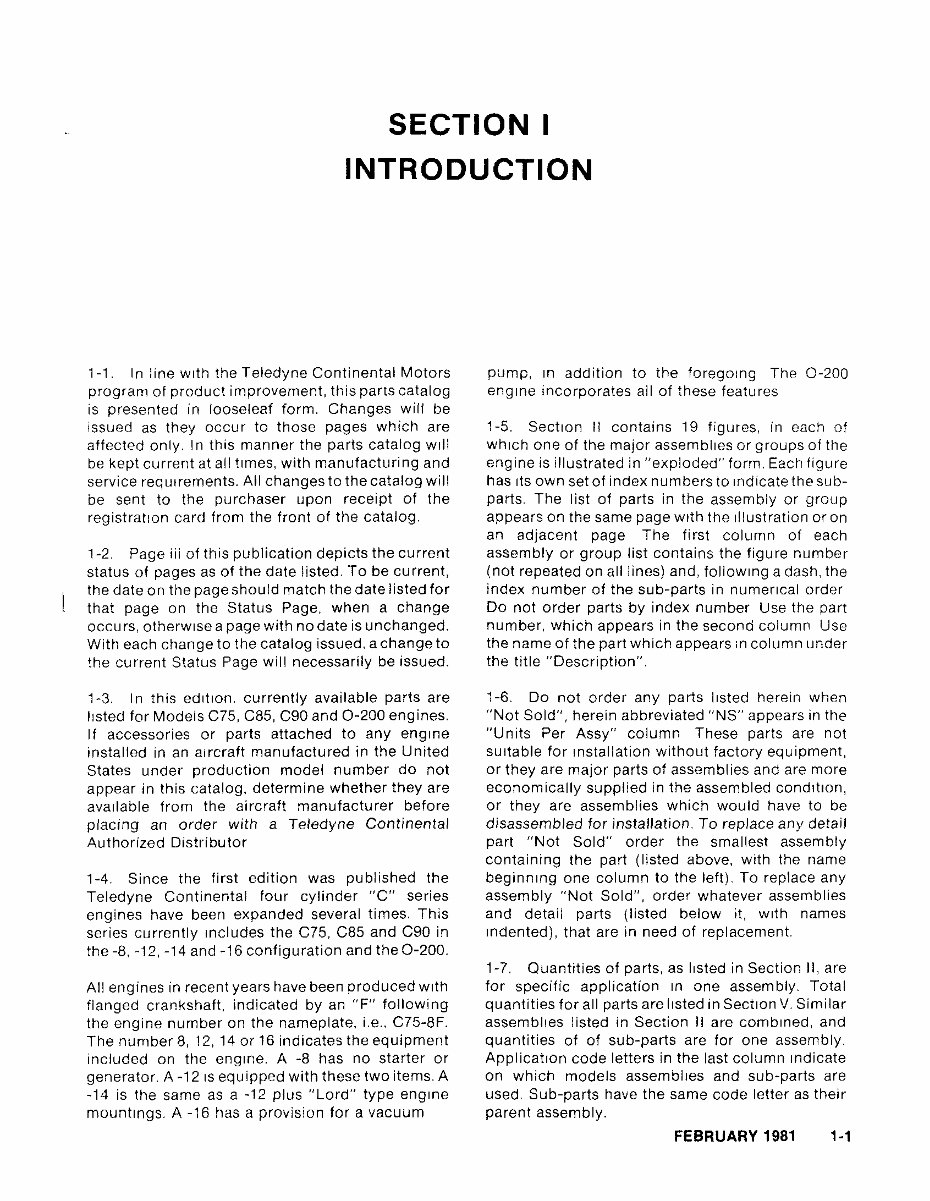
1-1. In line with the Teledyne Continental Motors
program of product improvement, this parts catalog
is presented in looseleaf form. Changes will be
issued as they occur to those pages which are
affected only. In this manner the parts catalog will
be kept current at all times, with manufacturing and
service req ulrements. All changes to the catalog will
be sent to the purchaser upon receipt of the
registration card from the front of the catalog.
1-2. Page iii of this publication depicts the current
status of pages as of the date listed. To be current,
the date on the page should match the date listed for
that page on the Status Page, when a change
occurs, otherwise a page with no date is unchanged.
With each change to the catalog issued. a change to
the current Status Page will necessarily be issued.
1-3. I n this edition. currently available parts are
listed for Models C75, C85, C90 and 0-200 engines.
If accessories or parts attached to any engine
installed in an aircraft manufactured in the United
States under production model number do not
appear in this catalog, determine whether they are
available from the aircraft manufacturer before
placing an order with a Teledyne Continental
Authorized Distributor
1-4. Since the first edition was published the
Teledyne Continental four cylinder "C" series
engines have been expanded several times. This
series currently Includes the C75, C85 and C90 in
the -8, -12, -14 and -16 configuration and the 0-200.
All engines in recent years have been produced With
flanged crankshaft, indicated by an "F" following
the engine number on the nameplate, i.e .. C75-8F.
The number 8,12,14 or 16 indicates the equipment
included on the engine. A -8 has no starter or
generator. A -12 IS equipped with these two items. A
-14 is the same as a -12 plus "Lord" type engine
mountings. A -16 has a provision for a vacuum
pump, In addition to the foregOing The 0-200
engine incorporates all of these features
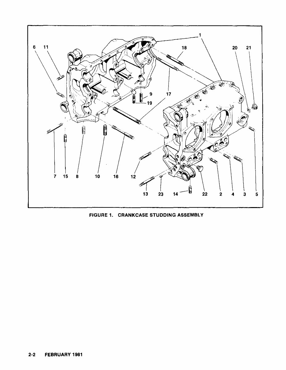
1-5. Section II contains 19 figures, in each of
which one of the major assemblies or groups of the
engine is illustrated in "exploded" form. Each figure
has ItS own set of index numbers to Indicate the sub-
parts. The list of parts in the assembly or group
appears on the same page With the Illustration or on
an adjacent page The first column of each
assembly or group list contains the figure number
(not repeated on all lines) and, follOWing a dash, the
index number of the sub-parts in numerical order
Do not order parts by index number Use the part
number, which appears in the second column Use
the name of the part which appears In column under
the title "Description".
1-6. Do not order any parts listed herein when
"Not Sold", herein abbreviated "NS" appears in the
"Units Per Assy" column These parts are not
SUitable for Installation without factory equipment,
or they are major parts of assemblies and are more
economically supplied in the assembled condition,
or they are assemblies which would have to be
disassembled for installation. To replace any detail
part "Not Sold" order the smallest assembly
containing the part (listed above, with the name
beginning one column to the left). To replace any
assembly "Not Sold", order whatever assemblies
and detail parts (listed below it, With names
Indented), that are in need of replacement.
1-7. Quantities of parts, as listed in Section II, are
for specific application In one assembly. Total
quantities for all parts are listed in Section V. Similar
assemblies listed in Section II are combined, and
quantities of of sub-parts are for one assembly.
Application code letters in the last column Indicate
on which models assemblies and sub-parts are
used. Sub-parts have the same code letter as their
parent assembly.
FEBRUARY 1981 1-1
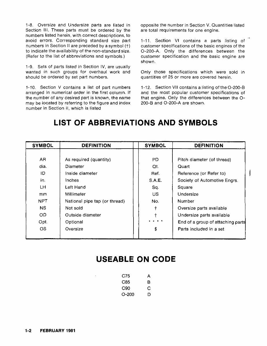
1-8. Oversize and Undersize parts are listed in
Section III. These parts must be ordered by the
numbers listed herein, with correct descriptions, to
avoid errors. Corresponding standard size part
numbers in Section II are preceded by a symbol (t)
to indicate the availability of the non-standard size.
(Refer to the list of abbreviations and symbols.)
1-9. Sets of parts listed in Section IV, are usually
wanted in such groups for overhaul work and
should be ordered by set part numbers.
1-10. Section V contains a list of part numbers
arranged in numerical order in the first column. If
the number of any desired part is known, the name
may be located by referring to the figure and index
number in Section II, which is listed
opposite the number in Section V. Quantities listed
are total requirements for one engine.
1-11. Section VI contains a parts listing of
customer specifications of the basic engines of the
0-200-A. Only the differences between the
customer specification and the basic engine are
shown.
Only those specifications which were sold in
quantities of 25 or more are covered herein.
1-12. Section VII contains a listing oftheO-200-B
and the most popular customer specifications of
that engine. Only the differences between the 0-
200-B and 0-200-A are shown.
LIST OF ABBREVIATIONS AND SYMBOLS
SYMBOL DEFINITION SYMBOL DEFINITION
AR As required (quantity) PD Pitch diameter (of thread)
dia. Diameter Qt. Quart
ID Inside diameter Ref. Reference (or Refer to)
in. Inches S.A.E. Society of Automotive Engrs.
LH Left Hand Sq. Square
mm Millimeter US Undersize
NPT National pipe tap (or thread) No. Number
NS Not sold
t
Oversize parts available
OD Outside diameter
t
Undersize parts available
Opt. Optional
• • • •
End of a group of attaching part,
OS Oversize $ Parts included in a set
USEABLE ON CODE
C75 A
C85 B
C90 C
0-200 D
1-2 FEBRUARY 1981
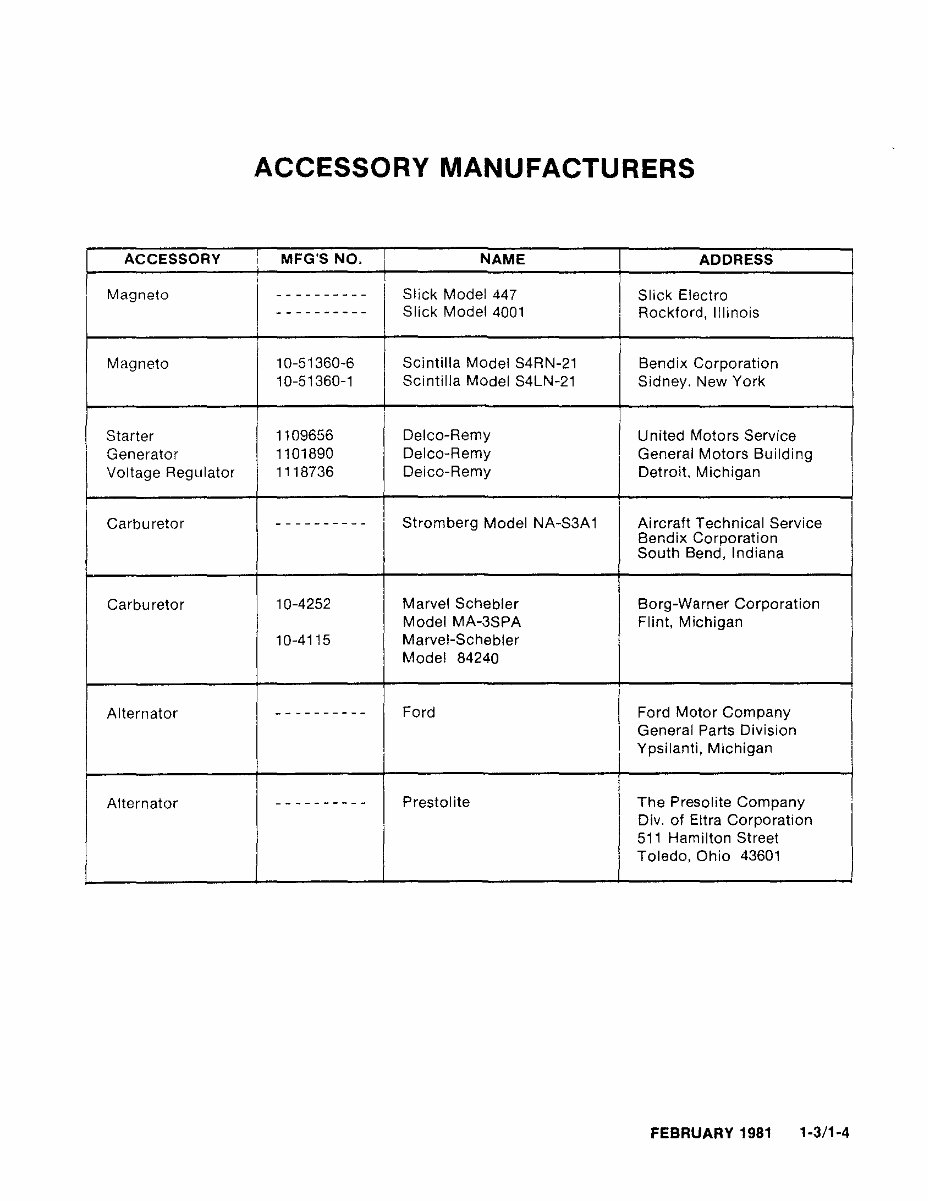
ACCESSORY MANUFACTURERS
ACCESSORY
,
MFG'S NO. NAME ADDRESS
,
,
Magneto
I
-- --------
Slick Model 447 Slick Electro
---------- Slick Model 4001 Rockford, Illinois
Magneto 10-51360-6 Scintilla Model S4RN-21 Bendix Corporation
10-51360-1 Scintilla Madel S4LN-21 Sidney. New York
Starter 1109656 Delco-Remy United Motors Service
I
Generator 1101890 Delco-Remy General Motors Building
Voltage Regulator 1118736 Delco-Remy Detroit. Michigan
Carburetor ---------- Stromberg Model NA-S3A 1 Aircraft Technical Service
Bendix Corporation
South Bend, Indiana
Carbu retor 10-4252 Marvel Schebler Borg-Warner Corporation
i
Model MA-3SPA Flint, Michigan
10-4115 Marvel-Schebler
Model 84240
,
I
Alternator
---------- Ford Ford Motor Company
I
General Parts Division
Ypsilanti, Michigan
,
Alternator
---------- Prestolite The Presolite Company
I
Div. of Eltra Corporation
511 Hamilton Street
Toledo, Ohio 43601
FEBRUARY 1981 1-3/1-4

SECTION II
GROUP ASSEMBLY PARTS LIST
FEBRUARY 1981 2-1
6
\
11
\
7 15 8 10 16
1
"-----
20 21
\
//
/ '
12
--
13 23 14 22 2 4 3 5
FIGURE 1. CRANKCASE STUDDING ASSEMBLY
2-2 FEBRUARY 1981
You're Reading a Preview
What's Included?
Fast Download Speeds
Offline Viewing
Access Contents & Bookmarks
Full Search Facility
Print one or all pages of your manual
$30.99
Viewed 67 Times Today


Secure transaction
What's Included?
Fast Download Speeds
Offline Viewing
Access Contents & Bookmarks
Full Search Facility
Print one or all pages of your manual
$30.99
Get the Continental Aircraft Engines O200-C75-C85-C90 Parts Manual in PDF format. This manual is compatible with all versions of Windows, Mac, and Linux. It is printable and can be accessed instantly at high speed. Adobe Reader is required to view the manual.


