

Caterpillar C7 / C9 Engines Electrical and Electronic Application and Installation Guide
What's Included?
Fast Download Speeds
Online & Offline Access
Access PDF Contents & Bookmarks
Full Search Facility
Print one or all pages of your manual

C7 & C9 Truck Engines
EPA 2004
Electrical and Electronic
Application and Installation Guide
Serial Number Prefixes
FMM
FML
KAL
YPG
9DG
CKP
LEBT2835-02 November 2008


INTRODUCTION AND PURPOSE . . . . . . . . . . . . . . . . . . . . . . . . . . . . . . . . . . . . . . . . . . . . . . . . . . . . . 4
Engine Functions . . . . . . . . . . . . . . . . . . . . . . . . . . . . . . . . . . . . . . . . . . . . . . . . . . . . . . . . . . . . . . . . . . . . .4
Engine Component Overview . . . . . . . . . . . . . . . . . . . . . . . . . . . . . . . . . . . . . . . . . . . . . . . . . . . . . . . . . . .5
Engine Monitoring . . . . . . . . . . . . . . . . . . . . . . . . . . . . . . . . . . . . . . . . . . . . . . . . . . . . . . . . . . . . . . . . . . .12
Power and Grounding Requirements and Considerations . . . . . . . . . . . . . . . . . . . . . . . . . . . . . . . . . . . . .19
Connectors and Wiring Harness Requirements . . . . . . . . . . . . . . . . . . . . . . . . . . . . . . . . . . . . . . . . . . . . .26
Accelerator Pedal Position Sensors . . . . . . . . . . . . . . . . . . . . . . . . . . . . . . . . . . . . . . . . . . . . . . . . . . . . . .32
Vehicle Speed Input Circuit . . . . . . . . . . . . . . . . . . . . . . . . . . . . . . . . . . . . . . . . . . . . . . . . . . . . . . . . . . . .38
ECM Speedometer and Tachometer Outputs . . . . . . . . . . . . . . . . . . . . . . . . . . . . . . . . . . . . . . . . . . . . . .42
Lamp Outputs . . . . . . . . . . . . . . . . . . . . . . . . . . . . . . . . . . . . . . . . . . . . . . . . . . . . . . . . . . . . . . . . . . . . . .45
OEM Installed Sensors . . . . . . . . . . . . . . . . . . . . . . . . . . . . . . . . . . . . . . . . . . . . . . . . . . . . . . . . . . . . . . .50
Inlet Air Heater, Lamp and Relay Operation . . . . . . . . . . . . . . . . . . . . . . . . . . . . . . . . . . . . . . . . . . . . . . .56
Hard-wired Switch Inputs . . . . . . . . . . . . . . . . . . . . . . . . . . . . . . . . . . . . . . . . . . . . . . . . . . . . . . . . . . . . .60
Cruise Control . . . . . . . . . . . . . . . . . . . . . . . . . . . . . . . . . . . . . . . . . . . . . . . . . . . . . . . . . . . . . . . . . . . . . .68
Idle Functions . . . . . . . . . . . . . . . . . . . . . . . . . . . . . . . . . . . . . . . . . . . . . . . . . . . . . . . . . . . . . . . . . . . . . .70
J1939 Based Switch Messages . . . . . . . . . . . . . . . . . . . . . . . . . . . . . . . . . . . . . . . . . . . . . . . . . . . . . . . . .72
Dedicated PTO Operation . . . . . . . . . . . . . . . . . . . . . . . . . . . . . . . . . . . . . . . . . . . . . . . . . . . . . . . . . . . . .75
Programmable Outputs . . . . . . . . . . . . . . . . . . . . . . . . . . . . . . . . . . . . . . . . . . . . . . . . . . . . . . . . . . . . . . .94
Transmissions . . . . . . . . . . . . . . . . . . . . . . . . . . . . . . . . . . . . . . . . . . . . . . . . . . . . . . . . . . . . . . . . . . . . . .100
Governor Type . . . . . . . . . . . . . . . . . . . . . . . . . . . . . . . . . . . . . . . . . . . . . . . . . . . . . . . . . . . . . . . . . . . . .104
Cooling Fan . . . . . . . . . . . . . . . . . . . . . . . . . . . . . . . . . . . . . . . . . . . . . . . . . . . . . . . . . . . . . . . . . . . . . . .106
Idle Shutdown Timer . . . . . . . . . . . . . . . . . . . . . . . . . . . . . . . . . . . . . . . . . . . . . . . . . . . . . . . . . . . . . . . .113
Data Links . . . . . . . . . . . . . . . . . . . . . . . . . . . . . . . . . . . . . . . . . . . . . . . . . . . . . . . . . . . . . . . . . . . . . . . .114
Customer Specified Parameters . . . . . . . . . . . . . . . . . . . . . . . . . . . . . . . . . . . . . . . . . . . . . . . . . . . . . . . .144
Diagnostics, Service Tools and Service Information . . . . . . . . . . . . . . . . . . . . . . . . . . . . . . . . . . . . . . . .187
ELECTRICAL & ELECTRONIC APPLICATION AND INSTALLATION GUIDE
Caterpillar Pub # LEBT2835-02________C7 & C9 ACERT Truck Engines________EPA 2004_____ 3

INTR ODUCTION AND PURPOSE
This document is intended to provide necessary information for correct electrical & electronic application and
installation of a C7 or C9 truck engine into an on-highway truck, bus, motor coach or vocational chassis.
Caterpillar expects there will be some additions and modifications to this document as the engine program
development continues, and as OEM requests for information not currently addressed are added.The information
contained in this version of the document reflects the Caterpillar design for production C7 and C9 engines built
with March 2004 software.
General Electronic Engine Operation
1.0 Engine Functions
1.1 Electronic Governing
Two engine speed range electronic governors are available for use.These electronic governors are selectable
through a programmable parameter.
1.2 Fuel/Air Ratio Control
The control system has full authority over engine fuel delivery.The mechanical fuel/air ratio control is eliminated.
Electronic control of the fuel/air ratio provides optimum performance with reduced emissions.
1.3 Injection Timing Control
Injection timing is varied as a function of engine operating conditions to optimize engine performance for emissions,
noise, fuel consumption, and drivability.
1.4 Torque Rise Shaping
Electronic controls provide increased flexibility to tailor the torque curve over a wide speed range.
1.5 Cold Mode Operation
When the engine is started with cold coolant, the engine will operate in “Cold Mode”. The engine will operate with
reduced performance until the coolant temperature has warmed. The Caterpillar electronic service tool software will
indicate when the engine is operating in Cold Mode. The C7 engine will operate in Cold Mode below 64 Deg C and
the C9 engine will operate in Cold Mode below 40 Deg C.
ELECTRICAL & ELECTRONIC APPLICATION AND INSTALLATION GUIDE
4 Caterpillar Pub # LEBT2835-02________C7 & C9 ACERT Truck Engines________EPA 2004_____
The information herein is the property of Caterpillar Inc. and/or its subsidiaries. Without
written permission, any copying, transmittal to others, and any use except that for
which it is loaned is prohibited.

2.0 Engine Component Overview
2.1 Engine Control Module (ECM)
The ECM is located on the left rear side of the engine. The ECM has two connectors, one for the Caterpillar Engine
Harness, the other for the Vehicle OEM Harness.
2.2 Boost Pressure Sensor
The Boost Pressure Sensor is an absolute pressure sensor measuring inlet manifold pressure. Boost pressure
displayed by service tools and communicated over the data link is referenced to the Atmospheric Pressure Sensor
reading. The Boost Pressure Sensor measures gauge pressure from 0 psi (0 kPa) to 49 psi (340 kPa). The ECM
supplies the sensor with a regulated 5 Volts DC.
2.3 Atmospheric Pressure Sensor
The Atmospheric Pressure Sensor is an absolute pressure sensor. The Atmospheric Pressure Sensor measures
pressure to 16.8 psiA (116 kPaA).The ECM supplies the sensor with a regulated 5 Volts DC.
2.4 Oil Pressure Sensor
An optional Oil Pressure Sensor is available for use in applications where an actual oil pressure indication is
desired.Typical applications include vehicles with a vehicle data link capable Instrument Cluster that can display
engine information. C7 or C9 engines do not require Engine Lube Oil Pressure monitoring because the HEUI
(Hydraulically actuated Electronically controlled Unit Injector) fuel system requires oil pressure for the engine
to operate. Without sufficient oil pressure, the fuel system cannot supply fuel to the engine.
The Oil Pressure Sensor measures gauge pressure from 0 psi (0 kPa) to 165 psi (1135 kPa). Oil Pressure as
displayed by service tools and communicated over the data link is referenced to the Atmospheric Pressure Sensor
reading. The ECM supplies this sensor with the necessary voltage.
2.5 Coolant Temperature Sensor
The thermistor based Coolant Temperature Sensor is used to monitor engine coolant temperature. Output from
this sensor is used for several engine functions including Inlet Air Heater Operation, Cold Mode Operation,
Cold Elevated Idle and the Engine Monitoring System.
2.6 Inlet Manifold Air Temperature Sensor
The Inlet Manifold Air Temperature Sensor is used to measure the inlet air temperature and is thermistor based like
the Coolant Temperature Sensor.This sensor output is used in controlling the Inlet Air Heater, Cold Elevated Idle,
Cooling Fan Output, and for Engine Monitoring.
2.7 Engine Speed/Timing Sensors
The engine speed/timing sensors are used to determine both engine speed and fuel injection timing. The sensors
detect this information from a wheel on the camshaft.
2.8 Coolant Level Sensor
The coolant level sensor is an option device used to monitor the engine’s coolant level.This sensor is usually
mounted in the cooling system’s surge tank. There are three types of sensors that may be used.
2.9 Injection Actuation Pressure (IAP) Sensor
The Injection Actuation Pressure Sensor measures the pressure in the high-pressure oil manifold. This oil is used
to feed the hydraulically actuated electronically controlled unit injectors. The ECM supplies the sensor with the
necessary voltage.
2.10 Injection Actuation Pressure Control Valve (IAPCV)
This valve controls the output injection actuation pressure of the high-pressure oil pump. The ECM uses the output
of the Injection Actuation Pressure Sensor to determine the required output to this valve.
ELECTRICAL & ELECTRONIC APPLICATION AND INSTALLATION GUIDE
Caterpillar Pub # LEBT2835-02________C7 & C9 ACERT Truck Engines________EPA 2004_____ 5
ELECTRICAL & ELECTRONIC APPLICATION AND INSTALLATION GUIDE
6 Caterpillar Pub # LEBT2835-02________C7 & C9 ACERT Truck Engines________EPA 2004_____
2.11 Inlet Air Heater and Relay
The Inlet Air Heater is an engine mounted, Caterpillar supplied and installed heater grid used for warming the inlet
air to aid in starting during cold ambient temperatures. Operation is based on elevation (above sea level) and the
sum of the Coolant and Inlet Manifold Air temperatures. The ECM controls the normally open relay to provide
battery power to the grid.
2.12 Fuel Pressure Sensor
A Fuel Pressure sensor is included in the engine pressure sensor package. This sensor monitors the fuel supply
pressure to the engine.
2.13 Oil Level Switch (GMT560 Trucks Only)
An Oil Level Switch is available only on General Motors engines.This switch is mounted in the oil pan and wired
to the Engine Connector (J2) of the ECM.This switch monitors the oil level in the oil pan and is checked at initial
engine power up. Proper Oil level in the engine will keep a normally open switch closed. Oil level that is too low
will allow the switch to open. If the ECM senses an open switch upon three sequential engine starts, low oil level
is indicated.
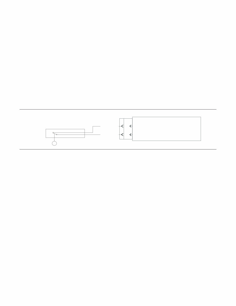
Figure 1
33
3
P2 J2
Sensor Common
Oil Level
ECM
Oil Level Switch
(Shown With Oil Level Normal)
B428-OR
G829-GN
ELECTRICAL & ELECTRONIC APPLICATION AND INSTALLATION GUIDE
Caterpillar Pub # LEBT2835-02________C7 & C9 ACERT Truck Engines________EPA 2004_____ 7
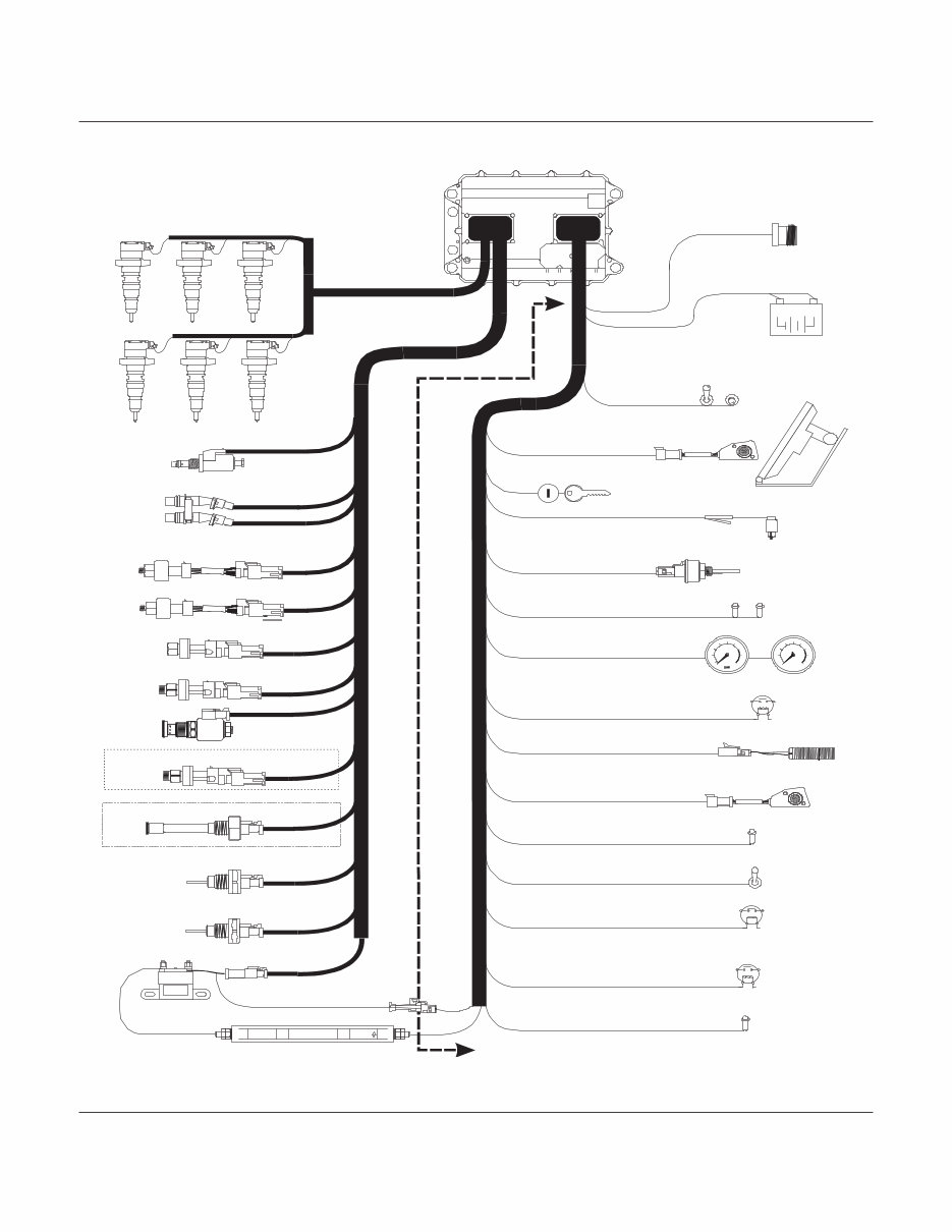
Figure 2
Boost Pressure Sensor
Top Camshaft Position Sensor
Bottom Camshaft Position Sensor
12V
ñ
+
BATTERIES
6 HEUI Injectors
Injection Actuation Pressure Control Valve
Injection Actuation Pressure Sensor
Atmospheric Pressure Sensor
Coolant Level Sensor
Coolant Temperature Sensor
Intake Manifold Air Temperature Sensor
109-3000
12 V
AIR FLOW
Intake Air Heater
Intake Air Heater Relay
Intake Air Heater Lamp
Vehicle Speed Sensor
Cooling Fan
SAE J1939/13 OFF-BOARD
DIAGNOTSIC CONNECTOR
Ignition Key Switch
2 +Battery & 9 Ground Switch Inputs
3, 1.5A Outputs
3, 1.0A Outputs
2, 0.3A Lamp Outputs
Clutch and Service Brake Switches
Check Engine & Warning Lamps
MPH
15
5
0
25
45
35 55
65
75
85 RPM X 100
5
10
15
20
25
30
Speedometer & Tachometer
Throttle Position Sensor
PTO Throttle Position Sensor
OEM Installed
Caterpillar Installed
Cruise Control On/Off
& Set/Resume Switches
ADEM 2000
Engine
Control
Module
Engine Oil Pressure Sensor (Optional)
Oil Level Switch (GMT560 Trucks Only)
Turbo Wastegate
Control Valve
(Not All Ratings)
Fuel Pressure Sensor
ELECTRICAL & ELECTRONIC APPLICATION AND INSTALLATION GUIDE
8 Caterpillar Pub # LEBT2835-02________C7 & C9 ACERT Truck Engines________EPA 2004_____
Engine
Oil
Pressure
Sensor
(Optional)
Coolant
Temperature
Sensor
Engine
Speed/Timing
Sensors
Injection Actuation
Control Valve
Injection Pressure
Sensor
Boost Pressure
Sensor
Inlet Air
Temperature
Sensor
Inlet Air
Heater
Relay
OEM
Connector
J1/P1
ECM
Engine
Connector
J2/P2
ECM
Inlet Air
Heater Relay
Atmospheric Pressure Sensor
Inlet Air
Temperature
Sensor
Boost Pressure
Sensor
Injection Actuation
Pressure
Control Valve
Coolant
Temperature
Sensor
Injection
Actuation
Pressure
Sensor
Speed/Timing
Sensors
Oil
Pressure
Sensor
(Optional)
OEM Harness
Connector
J1/P1
Engine
Harness
Connector
J2/P2
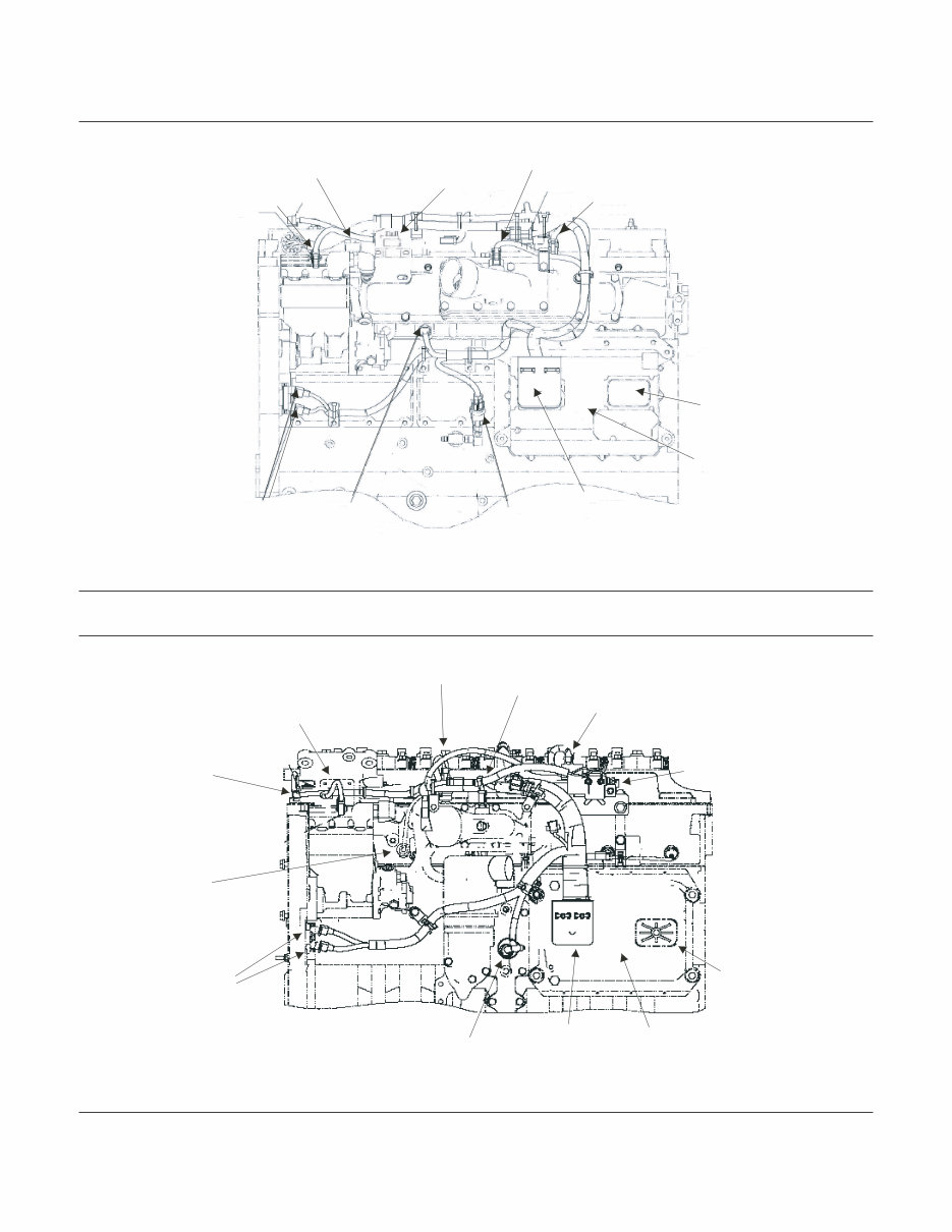
Figure 3 - C7 Sensor Locations
Figure 4 - C9 Sensor Locations
ELECTRICAL & ELECTRONIC APPLICATION AND INSTALLATION GUIDE
Caterpillar Pub # LEBT2835-02________C7 & C9 ACERT Truck Engines________EPA 2004_____ 9
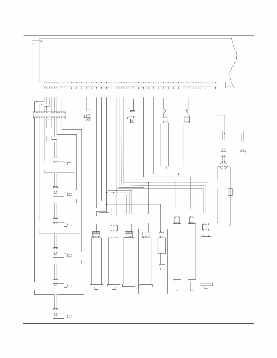
Figure 5 - C7 Engine Wiring Diagram
1
2
INJECTION ACTUATION
PRESSURE CONTROL VALVE
J500 P500
E963-BK
E964-WH
E965-BU
E966-YL
49
48
13
19
20
21
28
29
30
59
58
31
43
51
22
23
56
57
65
60
69
8
A
B
TOP CAMSHAFT
POSITION SENSOR
TOP CAMSHAFT POSITION -
TOP CAMSHAFT POSITION +
J401 P401
J402 P402
B
A
BOTTOM CAMSHAFT POSITION -
BOTTOM CAMSHAFT POSITION +
BOTTOM CAMSHAFT
POSITION SENSOR
995-BU
C967-BU
G833-PK
C
B
A
G849-BR
G829-GN
G828-WH
A746-PK
G849-BR
A747-GY
G829-GN
G828-WH
P204 J204
ENGINE ATMOSPHERIC PRESSURE
ENGINE PRESSURE SENSOR COMMON
ENGINE PRESSURE SENSOR +5V
ENGINE ATMOSPHERIC
PRESSURE
NOTE A
ENGINE INJECTION
ACTUATION
PRESSURE
ENGINE INJECTION ACTUATION PRESSURE
ENGINE PRESSURE SENSOR COMMON
ENGINE PRESSURE SENSOR +5V
P203
A747-GY
G829-GN
G828-WH
A
B
C
P200
A746-PK
G829-GN
G828-WH
SENSOR
ENGINE BOOST
PRESSURE
ENGINE BOOST PRESSURE
ENGINE PRESSURE SENSOR COMMON
ENGINE PRESSURE SENSOR +5V
GN
YL
0R
INTAKE AIR HEATER RELAY
ENGINE COOLANT TEMPERATURE
ENGINE INTAKE MANIFOLD AIR TEMP.
ENGINE TEMPERATURE SENSOR COMMON
ENGINE ATMOSPHERIC PRESSURE
ENGINE PRESSURE SENSOR COMMON
ENGINE PRESSURE SENSOR +5V
IAP CONTROL VALVE
IAP CONTROL VALVE COMMON
ENGINE BOOST PRESSURE
ENGINE INJECTION ACTUATION PRESSURE
P1 J1
ECM GROUND STRAP
G854-PK
G855-PU
TO ECM
MOUNTING
BOLT
ENGINE HARNESS CONNECTOR
VEHICLE HARNESS CONNECTOR
C987-RD
G850-BU
P648
TO CONNECTOR J648
(OEM HARNESS)
A
B
K995-OR
G850-BU
C987-RD
1
2
ENGINE TIMING CALIBRATION PROBE+
ENGINE TIMING CALIBRATION PROBE-
TO INTAKE AIR HEATER
CIRCUIT PROTECTION
(BATTERY +)
TO ENGINE CYLINDER HEAD
INTAKE AIR
HEATER
G850-BU
P2 J2
J501 P501
N/O
RELAY
32
35
7
34
26
18
10
11
12
15
16
17
24
27
41
42
50
52
53
66
9
40
25
6
33
14
3
2
B
A
INJECTOR
CYLINDER
NO.5
1
63
64
4
5
61
62
70
INJECTOR
CYLINDER
NO.6
B
A
J306 P306 J305 P305
J304 P304 J303 P303
J302 P302
L984-OR
B
A
INJECTOR
CYLINDER
NO.4
J301 P301
INJECTOR
CYLINDER
NO.1
A704-GN
B
A
A705-BU
A703-BR
A702-PU
A701-GY
L985-YL
L984-OR
A706-GY
L985-YL
L983-WH
L983-WH
INJECTOR
CYLINDER
NO.3
B
A
B
A
INJECTOR
CYLINDER
NO.2
P300 J300
L983-WH
L984-OR
L985-YL
A706-GY
A705-BU
A704-GN
A703-BR
A702-PU
A701-GY
INJECTOR COMMON CYLINDERS 1 & 2
INJECTOR COMMON CYLINDERS 3 & 4
INJECTOR COMMON CYLINDERS 5 & 6
INJECTOR CYLINDER 6
INJECTOR CYLINDER 5
INJECTOR CYLINDER 4
INJECTOR CYLINDER 3
INJECTOR CYLINDER 2
INJECTOR CYLINDER 1
44
45
46
55
54
39
38
37
36
47
67
68
12
11
10
9
8
7
6
5
4
3
2
1
SENSOR
1
2
ENGINE COOLANT
TEMPERATURE
995-BU
G833-PK
J100 P100
ENGINE COOLANT TEMPERATURE
ENGINE TEMPERATURE SENSOR COMMON
ENGINE INTAKE MANIFOLD AIR TEMPERATURE
ENGINE TEMPERATURE SENSOR COMMON
J103 P103
C967-BU
G833-PK
ENGINE INTAKE
MANIFOLD AIR
TEMPERATURE
1
2
SENSOR
SENSOR
SENSOR
NOTE A: INDICATES AN OPTIONAL COMPONENT NOT INSTALLED ON ALL ENGINES
ENGINE OIL PRESSURE
ENGINE OIL PRESSURE SENSOR COMMON
ENGINE OIL PRESSURE SENSOR +5V
P201
994-GY
G827-BU
G826-BR
994-GY
G827-BU
G826-BR
ENGINE OIL
PRESSURE
NOTE A
SENSOR
ENGINE OIL PRESSURE
ENGINE OIL PRESSURE SENSOR COMMON
ENGINE OIL PRESSURE SENSOR +5V
TOP CAMSHAFT POSITION -
TOP CAMSHAFT POSITION +
BOTTOM CAMSHAFT POSITION -
BOTTOM CAMSHAFT POSITION +
A
B
C
A
B
C
ENGINE OIL
LEVEL
SWITCH
(GMT560 Only)
G458-GY
OIL LEVEL SWITCH
1
2
M 795-WH
C211-BK
TURBO WASTEGATE SOL NEGATIVE
TURBO WASTEGATE SOL POSITIVE
TURBO WASTEGATE SOLENOID
*** Not On All Ratings ***
OIL Level -
OIL Level -
A
B
C
B
A
C991-PK
G827-BU
G826-BR
P205 J205
ENGINE FUEL PRESSURE
SENSOR COMMON
SENSOR +5V
GN
YL
0R
C991-PK
FUEL PRESSURE
FUEL TRANSFER
PUMP PRESSURE
ELECTRICAL & ELECTRONIC APPLICATION AND INSTALLATION GUIDE
10 Caterpillar Pub # LEBT2835-02________C7 & C9 ACERT Truck Engines________EPA 2004_____
A
B
J500 P500
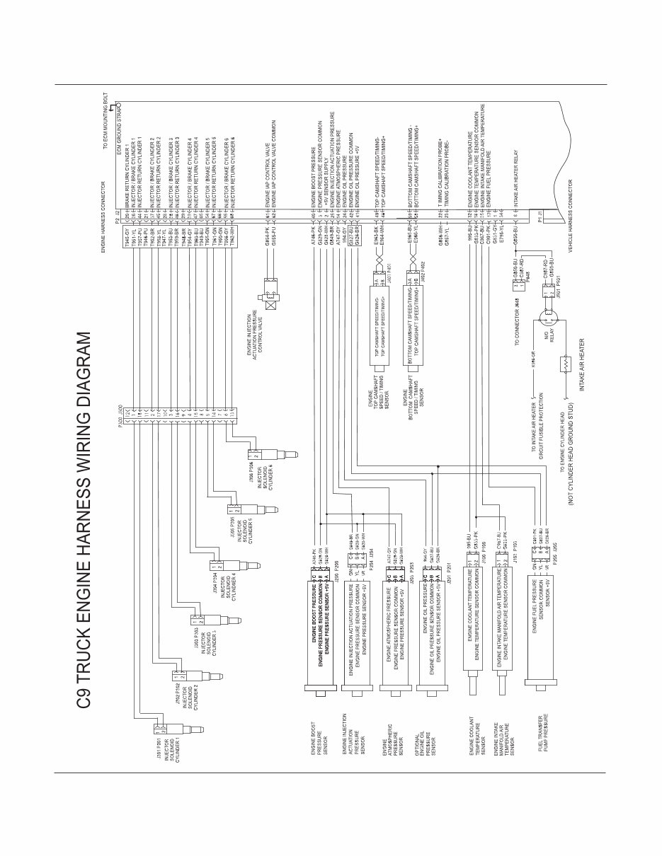
Figure 6 - C9 Engine Wiring Diagram
You're Reading a Preview
What's Included?
Fast Download Speeds
Online & Offline Access
Access PDF Contents & Bookmarks
Full Search Facility
Print one or all pages of your manual
$55.99
Viewed 58 Times Today


Secure transaction
What's Included?
Fast Download Speeds
Online & Offline Access
Access PDF Contents & Bookmarks
Full Search Facility
Print one or all pages of your manual
$55.99
Caterpillar C7 & C9 Truck Engines | Electrical and Electronic Application and Installation Guide
Serial Number Prefixes:
- FMM
- FML
- KAL
- YPG
- 9DG
- CKP
This manual provides essential information for the correct electrical and electronic application and installation of a C7 or C9 truck engine into on-highway trucks, buses, motor coaches, or vocational chassis.
The content reflects the Caterpillar design for production C7 and C9 engines built with March 2004 software.
Table of Contents:
- Introduction and Purpose
- Engine Functions
- Engine Component Overview
- Engine Monitoring
- Power and Grounding Requirements and Considerations
- Connectors and Wiring Harness Requirements
- Accelerator Pedal Position Sensors
- Vehicle Speed Input Circuit
- ECM Speedometer and Tachometer Outputs
- Lamp Outputs
- OEM Installed Sensors
- Inlet Air Heater, Lamp and Relay Operation
- Hard-wired Switch Inputs
- Cruise Control
- Idle Functions
- J1939 Based Switch Messages
- Dedicated PTO Operation
- Programmable Outputs
- Transmissions
- Governor Type
- Cooling Fan
- Idle Shutdown Timer
- Data Links
- Customer Specified Parameters
- Diagnostics, Service Tools and Service Information


