

3208 cat diesel truck engine service manual
What's Included?
Fast Download Speeds
Offline Viewing
Access Contents & Bookmarks
Full Search Facility
Print one or all pages of your manual
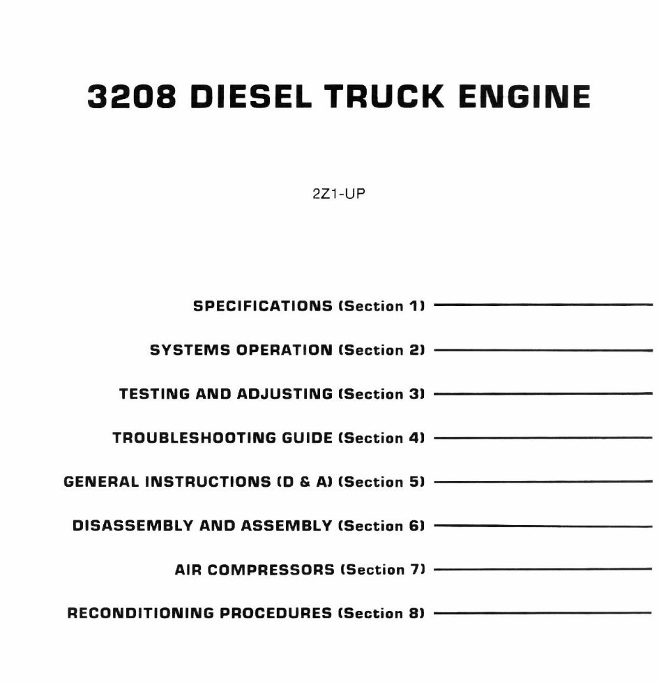
3208 DIESEL TRUCK ENGINE
2Z1-UP
SPECIFICATIONS (Section 11
SYSTEMS OPERATION (Section 21 -----------
TESTING AND ADJUSTING (Section 31
TROUBLESHOOTING GUIDE (Section 41
GENERAL INSTRUCTIONS (0 & AI (Section 51
DISASSEMBLY AND ASSEMBLY (Section 61
AIR COMPRESSORS (Section 71 ---------- -
RECONDITIONING PROCEDURES (Section 81
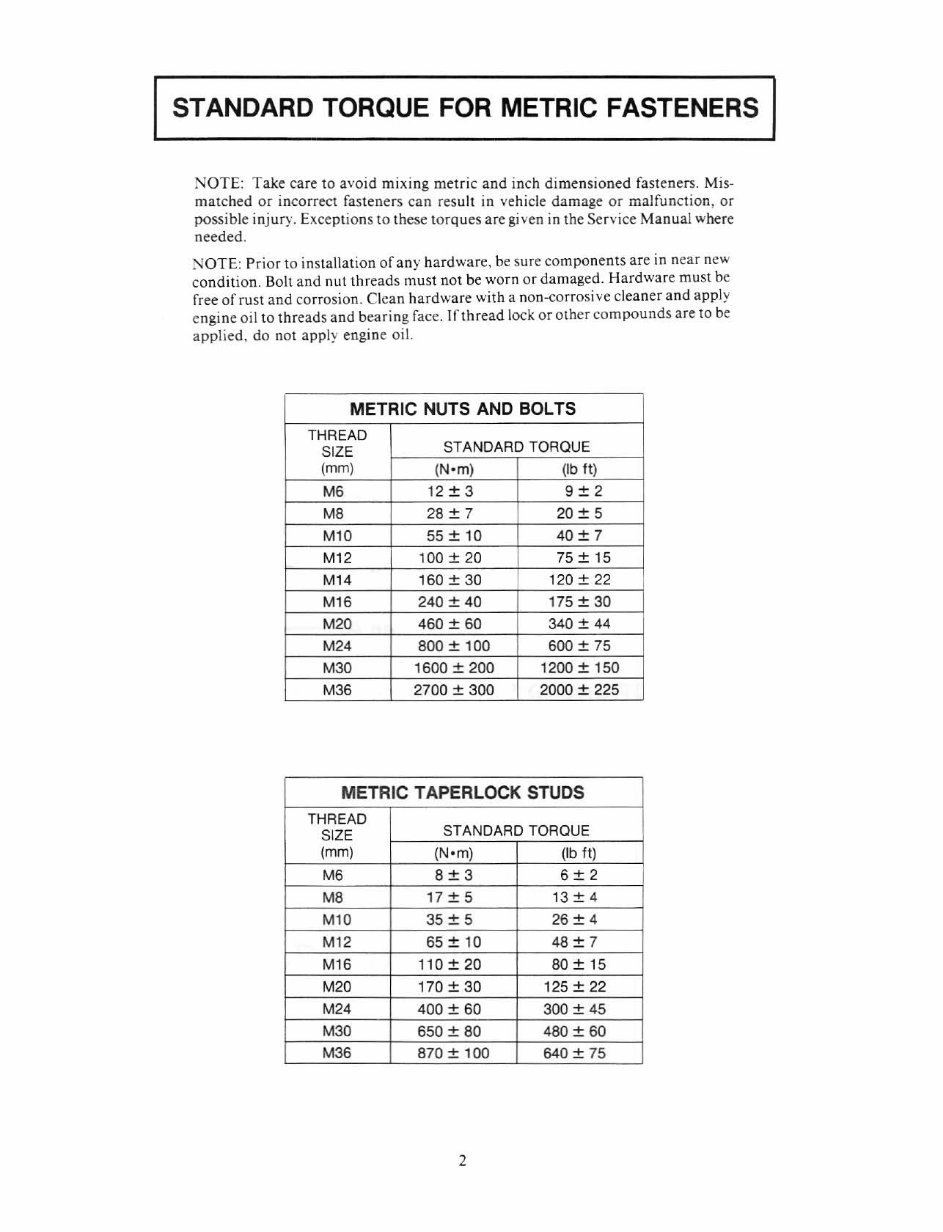
STANDARD TORQUE FOR METRIC FASTENERS
NOTE: Take care to avoid mIxing metric and inch dimensioned fasteners. Mis-
matched or Incorrect fasteners can result in vehicle damage or malfunction, or
possible injury. Exceptions to these torques are gi ven in the SeTyice Manual where
needed.
NOTE: P ri or to ins tallation of any hardware, be sure components are in near new
condition. Bolt and nut threads must not be worn or damaged. Hardware must be
free afrust and corrosion. Clean h ardware with a non-corrosive cleaner and app ly
cngine oil to threads and bea ring face. Iflhread lock or other compounds ar e to be
applied, do not app ly engine oil.
METRIC NUTS AND BOLTS
THREAD
SIZE
STANDARD TORQUE
(mm) (Nom) (Ib It)
M6 12 + 3 9+2
M8 28 ± 7 20 ± 5
M10 55 ± 10 40 ± 7
M12 100 + 20 75 + 15
M14 160 ± 30 120±22
M16 240 + 40 175 + 30
M20 460 ± 60
I
340 ± 44
M24 800 + 100 600 + 75
M30 1600 ± 200 1200±150
M36 2700 + 300 2000 + 225
METRIC TAPER LOCK STUDS
THREAD
SIZE
STANDARD TORQUE
(mm) (N om) (Ib It)
M6 8+3 6+2
M8 17 ± 5 13 ± 4
M10 35:t 5 26:t 4
M12 65 + 10 48+ 7
M16 110±20 80 ± 15
M20 170 + 30 125 + 22
M24 400 ± 60 300 ± 45
M30 650 + 80 480 + 60
M36 870 ± 100 640 ± 75
2
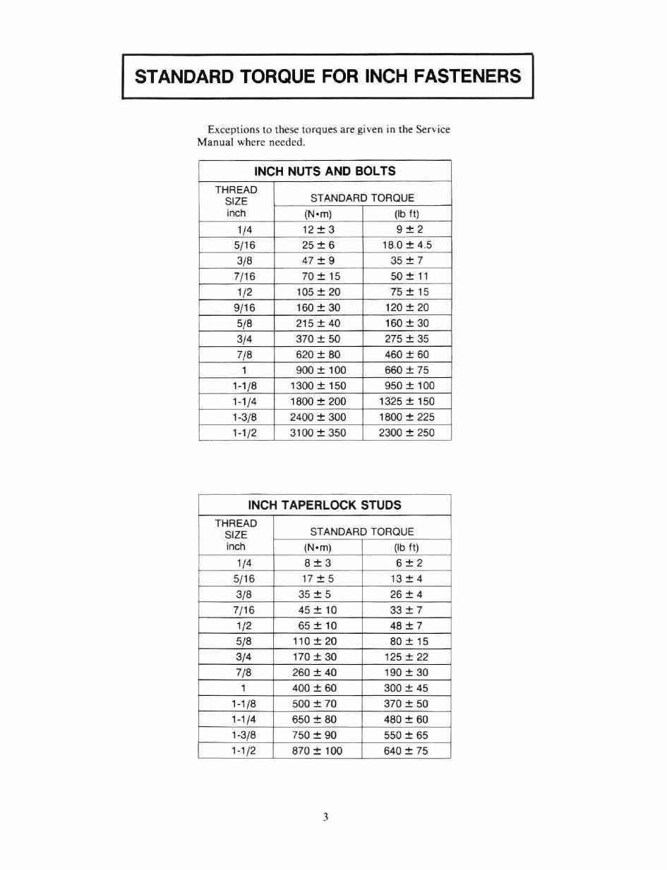
STANDARD TORQUE FOR INCH FASTENERS
Exceptions to these torques are given in the Service
Manua l where needed.
INCH NUTS AND BOLTS
THREAD
SIZE
STANDARD TORQUE
inch (N o m) (Ib II )
1/ 4 12 -+ 3 9+2
5/16 2S ± 6 18.0 ± 4 .5
3/8
47 + 9 35 + 7
7/16 70 -+ 15 50 + 11
1/ 2 105 -+ 20 75 -+ 15
9/16 160 + 30 120+20
5/8 215 ± 40 160±30
3/4 370 + 50 275 + 35
7/8 620 ± 80 460 ± 60
1 900 + 100 660 + 75
1-1 /8 1300 ± 150 950 ± 100
1-1/4 1800 + 200 1325 + 150
1-3/8 2400 + 300 1800 + 225
1-1 /2 3100 ± 350 2300 ± 250
INCH TAPERlOCK STUDS
THREAD
SIZE
5T ANDARO TORQUE
inch (Nom) lib II)
1/ 4 8±3 6±2
5/16 17 + 5 13 -+ 4
3/8 35 ± 5 26 ± 4
7/16 45 + 10 33 + 7
1/2 65 ± 10 48 + 7
5/8 110+20 80 + 15
3/4 170 + 30 125 + 22
7/8 260 + 40 190 + 30
1 400 + 60 300 + 45
1-1/8 500 ± 70 370 ± 50
1-1/4 650 + 80 480 + 60
1-3/8 750 ± 90 550 ± 65
1-1 /2 870 + 100 640 + 75
)
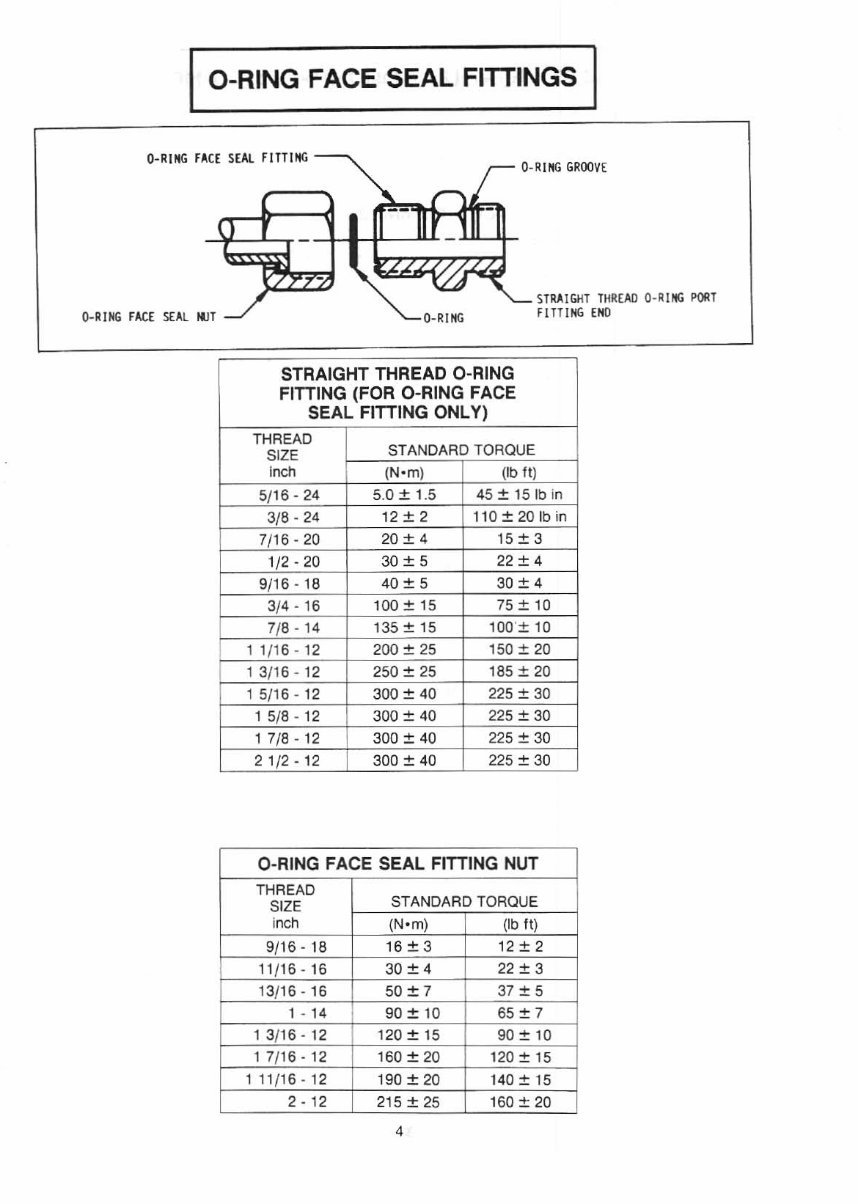
I O-RING FACE SEAL FITTINGS
O-RING FACE S EAl FITTING
O-R ING GROOVE
r-
.....
--II
-
STRAIGHT THREAD 0- """ POOT
-
O-RING FACE SEAL NUT
O -R ING FITTING END
STRAIGHT THREAD O-RING
FiniNG (FOR O-RING FACE
SEAL FiniNG ONLY)
THREAD
SIZE
STANDARD TORQUE
Inch (No m) (Ib II)
5/ 16 - 24 5.0 + 1.5 45 + lS lb in
3/8 - 24
12 + 2 110+201b in
7/16-20 20 + 4 15 + 3
1/2 - 20 30+ 5 22 + 4
9/16 - 18
40+ 5 30 + 4
3/4 - 16 100 + 15 75 + 10
7/8 - 14 135 + 15 100'+ 10
11 /1 6 - 12 200 + 25 150 + 20
13/1 6 - 12 250 + 25 185 + 20
15/16-12 300 + 40 22 5 + 30
15/ 8-12 300 + 40 225 + 30
17/8-12 300 + 40 225 + 30
21/2- 12 300 + 40 225 + 30
O-RING FACE SEAL FiniNG NUT
THREAD
SIZE
STANDARD TORQUE
inch (Nom) (Ib II)
9/16 - 18 16 + 3 12 + 2
11 /16 - 16 30 + 4 22 + 3
13/16 - 16 50 +7 37 + 5
1 - 14 90 + 10 65 + 7
13/16 - 12 120 + 15 90 + 10
17/16-12 160 + 20 120 + 15
111 /1 6 - 12 190 + 20 140 + 15
2 - 12 215 + 25 160 + 20
4

I FITTING INSTALLATION
HYDRAULIC LINE INSTALLATION
I. For a metal tube to hose insta ll ation. install the
tu be and lighten all bolts finger tight.
2. Tighten Ihe bolts al the rigid end.
3. In stall the hose and tighten all bolts finger tight.
4. Pullhc hose in a position so that it does not make
contact wi lh the mac hi ne or another hose.
5. Tighten the bolts on both connections.
6. Start the engi ne.
7. Move the implement co ntr ol levers to all
IXlsitions.
8. Look at the hose durin g movement of the imple-
me nt. Make s ur e hose is nol in contact with t he
machine or other hoses.
9. Shut off the engine.
10 . If necessary. put the hose in a new posit ion where
i! will not make co nt ac t when the implement is
moved.
ASSEMBLY OF FITIINGS WITH STRAIGHT
THREADS AND O-RING SEALS
T hi s type offit ting is used in many applications. The
tube end or the fitt ing will be di lTcrc nl in design so that
it can be used in many different app li calio ns. How·
ever, the installation proced ur e of the fitting is the
same. If the tube end o fl he fitting hody is Ihcsumc as
in t he illustration (either an elbow or a slraight body) il
will be necessary to assemble Ihe sleeve on Ihe luhe
before connecting the tube to the end.
3
--- 6
ELBOW BODY ASSSMBL Y
1. Endof fi ning body (connecl5lo tube ). 2. Fining body. 3. Lock ·
nut. 4. B8Ckup wuhet. 5. O-ring !Ie81. 6. End of fining 11181 goes
inlo other pl'Irt
5
I. Put locknut (3). backup washer (4) and O-ring seal
(5) as far back on fitting body (2) as possible. Holtl
these compo nents in this position. T urn the fitting
inlO Ihe par I it is used on until backup washer (4 )
ju st ma k es conta ct wi th the fuce of the part it IS
used on.
2. To putlhc fitting assembly in its correct position ,
turn Ihe fitting body (2) o ut (counterclockwise) a
maximum of 359°. Tighten l oc knut (3) to the
torque shown in the co rrect cha rt fo r the fitting
used.
NOTE : If the fitt ing is a connector (straight fitling),
the on the body takes the place of the locknut. To
insta ll this type filling, ti gh t en the hex against Ihe faec
of the part it goes into.
TORQUES FOR FLARED AND O-RING FITIINGS
The torques shown in the charts that follow ar c to be
used on the nut pan of 37· Flared, 45" Flared and
Inv erted Flared fittings (when used with steellubing).
O-ring plugs, O·r ing fittings and swivel nuts when used
in app li cations to 3000 psi (20 700 kPa).
HOSE CLAMP - BAND TYPE
CLAMP TORQUE ON RETIGHTENING
WIDTH NEW HOSE TORQUE
7.9 mm 0.9 ± 0.2 N· m 0.7 ± 0.2 Nom
(.312 in) 8 ± 21b in 6 ± 2 Ib in
13.5 mm 4.5 ± 0.5 Nom 3.0 ± 0.5 Nom
(.53 1 in) 40±5 1bin 25±Slbin
15.9 mm 7.5 ± 0.5 N-m 4.5 ± 0.5 Nom
(.625 in) 65±51bin 40±51bin
You're Reading a Preview
What's Included?
Fast Download Speeds
Offline Viewing
Access Contents & Bookmarks
Full Search Facility
Print one or all pages of your manual
$46.99
Viewed 16 Times Today


Secure transaction
What's Included?
Fast Download Speeds
Offline Viewing
Access Contents & Bookmarks
Full Search Facility
Print one or all pages of your manual
$46.99
A comprehensive service manual for the 3208 CAT diesel truck engine is an essential resource for both professional mechanics and DIY enthusiasts. This manual provides detailed technical information, including specifications, maintenance procedures, troubleshooting guides, and repair instructions. Whether you're performing routine maintenance or tackling more complex repairs, this manual equips you with the knowledge and guidance needed to keep the 3208 CAT diesel truck engine in optimal condition.


