

JVC HR-DVS2EA Service Manual
What's Included?
Fast Download Speeds
Online & Offline Access
Access PDF Contents & Bookmarks
Full Search Facility
Print one or all pages of your manual
SERVICE MANUAL
No. 82837
January 2001
HR-DVS2EU/EA
SPECIFICATIONS (The specifications shown pertain specifically to the model HR-DVS2EU)
Mini DV/S-VHS VIDEO CASSETTE RECORDER
Printed in Japan
VICTOR COMPANY OF JAPAN, LIMITED
VIDEO DIVISION
S40894
This service manual is printed on 100% recycled paper.
COPYRIGHT © 2001 VICTOR COMPANY OF JAPAN, LTD.
HR-DVS2EU/EA
No. 82837
625
TM
TM
T
V
P
R
+
T
V
P
R
–
T
V
–
T
V
+
1 2 3
4 5 6
7 8 9
1
2
1
2
3
VHS DV
TV
CABLE/SAT
TV/VCR
– –:– –
AUDIO
0000
START
DEBUT
STOP
FIN
DATE PR
DAILY/QTDN. VPS/PDC
AUX
WEEKLY/HEBDO
EXPRESS
LCD PROG
0
PROG
OK
3
4
4
MENU
30SEC
ENTER/ENTREE
VHS DV
A.DUB INSERT
PR
DUB
COPIE
DV VHS
START R.A.EDIT
IN/OUT
S-VHS ET
PULL-OPEN
GENERAL
Power requirement : AC 220 V – 240 V`,
50 Hz/60 Hz
Power consumption
Power on : 33 W
Power off : 7.9 W
Temperature
Operating : 5°C to 40°C
Storage : –20°C to 60°C
Operating position : Horizontal only
Dimensions (WxHxD) : 435 mm x 124 mm x 391 mm
Weight : 6.9 kg
Input/Output : 21-pin SCART connectors :
IN/OUT x 1, IN/DECODER x 1
RCA connectors:
VIDEO IN x 1, AUDIO IN x 1, AUDIO OUT x 1
S-Video connectors:
IN x 1, OUT x 1
DV connector: IN/OUT x 1
(4-pin, IEEE1394 conformity, digital input/output)
VHS DECK VIDEO/AUDIO
Signal system : PAL-type colour signal and CCIR monochrome
signal, 625 lines
50 fields
Recording system : DA4 (Double Azimuth) head helical scan system
Format : S-VHS/VHS PAL standard
Signal-to-noise ratio : 45 dB
Horizontal resolution
(SP/LP) : 250 lines (VHS)
400 lines (S-VHS)
(EP) : 220 lines (VHS)
350 lines (S-VHS)
Frequency range : 70 Hz to 10,000 Hz (Normal audio)
20 Hz to 20,000 Hz (Hi-Fi audio)
Maximum recording time
(SP) : 240 min. with E-240 video cassette
(LP) : 480 min. with E-240 video cassette
(EP) : 720 min. with E-240 video cassette
DV DECK VIDEO/AUDIO
Signal system : PAL-type colour signal, 625 lines
50 fields
Recording system : Digital Component Recording
Format : DV format (SD mode)
Cassette : Mini DV Cassette
Maximum recording time
(SP) : 60 min. with M-DV60ME cassette
(LP) : 90 min. with M-DV60ME cassette
Audio recording system
: PCM 48 kHz, 16 bit (2 ch)/
32 kHz, 12 bit (4 ch)
TUNER/TIMER
TV channel storage
capacity : 99 positions
(+AUX position)
Tuning system : Frequency synthesized tuner
Channel coverage : VHF 47 MHz – 89 MHz/
104 MHz – 300 MHz/
302 MHz – 470 MHz
UHF 470 MHz – 862 MHz
Memory backup time : Approx. 60 min.
ACCESSORIES
Provided accessories : RF cable,
21-pin SCART cable,
Satellite Controller RM-SD1,
Infrared remote control unit,
"R6" battery x 2
Specifications shown are for SP mode unless otherwise specified.
E.& O.E. Design and specifications subject to change without notice.

Important Safety Precautions
INSTRUCTIONS
1. DISASSEMBLY
1.1 HOW TO REMOVE THE MAJOR PARTS .................................................... 1-1
1.1.1 Introduction ............................................................................................ 1-1
1.2 HOW TO READ THE DISASSEMBLY AND ASSEMBLY .............................. 1-1
1.3 DISCONNECTION OF CONNECTORS (WIRES) ........................................ 1-1
1.4 SCREWS USED CABINET COMPONENTS AND BOARD ASSEMBLIES .......... 1-1
1.5 HOW TO REMOVE THE MAJOR PARTS <COM section> .......................... 1-2
1.5.1 Disassembly flow chart .......................................................................... 1-2
1.5.2 Disassembly/assembly method <COM section> ................................... 1-2
1.6 HOW TO REMOVE THE MAJOR PARTS <VHS section> ........................... 1-4
1.6.1 Disassembly flow chart .......................................................................... 1-4
1.6.2 DIsassembly/assembly method <VHS section> .................................... 1-4
1.7 HOW TO REMOVE THE MAJOR PARTS <DV section> .............................. 1-6
1.7.1 Disassembly flow chart .......................................................................... 1-6
1.7.2 Disassembly/assembly method <DV section> ....................................... 1-6
1.8 SERVICE POSITIONS .................................................................................. 1-8
1.8.1 Service position <VHS SIDE> ................................................................. 1-8
1.8.2 Service position <DV SIDE> .................................................................... 1-9
1.9 MECHANISM SERVICE MODE .................................................................. 1-10
1.9.1 How to set the "MECHANISM SERVICE MODE" ................................ 1-10
1.10 CONNECTION .......................................................................................... 1-11
1.11 EMERGENCY DISPLAY FUNCTION ........................................................ 1-13
1.11.1 Displaying the emergency information ................................................ 1-13
1.11.2 Clearing the emergency history ........................................................... 1-13
1.11.3 Emergency content description ........................................................... 1-14
1.11.4 Emergency detail information 1 .......................................................... 1-15
1.11.5 Emergency detail information 2 .......................................................... 1-16
2. MECHANISM ADJUSTMENT (VHS)
2.1 BEFORE STARTING REPAIR AND ADJUSTMENT ..................................... 2-1
2.1.1 Precautions ............................................................................................ 2-1
2.1.2 Checking for Proper Mechanical Operations ......................................... 2-1
2.1.3 Manually Removing the Cassette Tape ................................................. 2-1
2.1.4 Jigs and Tools Required for Adjustment ................................................. 2-2
2.1.5 Maintenance and Inspection .................................................................. 2-3
2.2 REPLACEMENT OF MAJOR PARTS ........................................................... 2-6
2.2.1 Before Starting Disassembling (Phase matching between
mechanical parts) ................................................................................... 2-6
2.2.2 How to Set the Mechanism Assembling Mode ....................................... 2-6
2.2.3 Cassette Holder Assembly ..................................................................... 2-6
2.2.4 Pinch Roller Arm Assembly .................................................................... 2-8
2.2.5 Guide Arm Assembly and Press Lever Assembly .................................. 2-8
2.2.6 Audio Control Head ................................................................................ 2-8
2.2.7 Loading Motor ........................................................................................ 2-8
2.2.8 Capstan Motor ....................................................................................... 2-9
2.2.9 Pole Base Assembly (supply or take-up side) ........................................ 2-9
2.2.10 Rotary Encoder .................................................................................. 2-10
2.2.11 Clutch Unit ......................................................................................... 2-10
2.2.12 Change Lever Assembly, Direct Gear, Clutch Gear and Coupling Gear ......... 2-10
2.2.13 Link Lever .......................................................................................... 2-11
2.2.14 Cassette Gear, Control Cam and Worm Gear ................................... 2-11
2.2.15 Control Plate ...................................................................................... 2-11
2.2.16 Loading Arm Gear (supply or take-up side) and Loading Arm Gear Shaft .......... 2-12
2.2.17 Take-up Lever, Take-up Head and Control Plate Guide .................... 2-13
2.2.18 Capstan Brake Assembly .................................................................. 2-13
2.2.19 Sub Brake Assembly (take-up side) .................................................. 2-13
2.2.20 Main Brake Assembly (take-up side), Reel Disk (take-up side)
and Main Brake Assembly (supply side) ............................................ 2-13
2.2.21 Tension Brake Assembly, Reel Disk (supply side) and
Tension Arm Assembly ...................................................................... 2-14
2.2.22 Idler Lever, Idler Arm Assembly ......................................................... 2-14
2.2.23 Stator Assembly ................................................................................. 2-14
2.2.24 Rotor Assembly ................................................................................. 2-14
2.2.25 Upper Drum Assembly ....................................................................... 2-15
2.3 COMPATIBILITY ADJUSTMENT ................................................................ 2-16
2.3.1 Checking/Adjustment of FM Waveform Linearity ................................. 2-16
2.3.2 Checking/Adjustment of the Height and Tilt of the Audio Control Head ........ 2-17
2.3.3 Checking/Adjustment of the Audio Control Head Phase (X-Value) ......... 2-17
2.3.4 Checking/Adjustment of the Standard Tracking Preset ....................... 2-18
2.3.5 Checking/Adjustment of the Tension Pole Position .............................. 2-18
MECHANISM ADJUSTMENT (DV)
2.9 PREPARATION ........................................................................................... 2-21
2.9.1 Precautions .......................................................................................... 2-21
2.9.2 Tools Required for Adjustments ........................................................... 2-21
2.9.3 Disassembly and Assembly Procedures .............................................. 2-21
2.9.4 Screws and Washers Used in Disassembly/Assembly of the
Mechanism Assembly .......................................................................... 2-21
2.10 DISASSEMBLY/ASSEMBLY OF THE MECHANISM ASSEMBLY ............. 2-22
2.10.1 Introduction ........................................................................................ 2-22
2.10.2 Mechanism Modes ............................................................................ 2-22
2.11 MECHANISM TIMING CHART .................................................................. 2-24
2.12 MECHANISM ASSEMBLY/DISASSEMBLY PROCEDURE TABLE ........... 2-25
2.13 DISASSEMBLY/ASSEMBLY ...................................................................... 2-27
2.14 LIST OF PROCEDURES FOR DISASSEMBLY ........................................ 2-35
2.15 MECHANISM DISASSEMBLY/ASSEMBLY SHEET .................................. 2-36
2.16 MECHANISM PHASE CHECK/ADJUSTMENT ......................................... 2-38
2.17 POSITIONING THE TENSION POLE ........................................................ 2-39
2.18 COMPATIBILITY AND ERROR RATE ADJUSTMENTS ............................ 2-40
2.18.1 Preparation ........................................................................................ 2-40
2.18.2 Adjustment ......................................................................................... 2-40
2.18.3 Linearity adjustment .......................................................................... 2-41
2.18.4 PB switching point adjustment ........................................................... 2-41
2.18.5 Error rate adjustment ......................................................................... 2-41
2.18.6 Error rate measuring method ............................................................. 2-41
2.19 TAPE EJECTION ....................................................................................... 2-42
TABLE OF CONTENTS
Section Title Page Section Title Page
3. ELECTRICAL ADJUSTMENT (VHS)
3.1 PRECAUTION .............................................................................................. 3-1
3.1.1 Required test equipments ...................................................................... 3-1
3.1.2 Required adjustment tools ..................................................................... 3-1
3.1.3 Color (colour) bar signal,Color (colour) bar pattern ............................... 3-1
3.1.4 Switch settings and standard precautions ............................................. 3-1
3.1.5 EVR Adjustment ..................................................................................... 3-1
3.2 SERVO CIRCUIT .......................................................................................... 3-2
3.2.1 Switching point ....................................................................................... 3-2
3.2.2 Slow tracking preset ............................................................................... 3-2
3.3 VIDEO CIRCUIT ........................................................................................... 3-2
3.3.1 D/A level ................................................................................................. 3-2
3.3.2 EE Y level ............................................................................................... 3-3
3.3.3 PB Y level (S-VHS / VHS) ...................................................................... 3-3
3.3.4 REC color (colour) level ......................................................................... 3-3
3.3.5 Video EQ (Frequency response) ........................................................... 3-4
3.3.6 AUTO PICTURE initial setting ............................................................... 3-4
3.3.7 DV EE Y level ......................................................................................... 3-4
3.4 AUDIO CIRCUIT ........................................................................................... 3-5
3.4.1 Audio REC FM ....................................................................................... 3-5
3.5 SYSCON CIRCUIT ....................................................................................... 3-5
3.5.1 Timer clock ............................................................................................. 3-5
ELECTRICAL ADJUSTMENT (DV)
3.6 PREPARATION ............................................................................................. 3-6
3.6.1 Precautions ............................................................................................ 3-6
3.6.2 Equipment required for adjustment ........................................................ 3-6
3.6.3 Tools required for adjustments ............................................................... 3-6
3.6.4 Setup ...................................................................................................... 3-6
4. CHARTS AND DIAGRAMS
NOTES OF SCHEMATIC DIAGRAM ................................................................... 4-1
CIRCUIT BOARD NOTES .................................................................................... 4-2
4.1 BOARD INTERCONNECTIONS ................................................................... 4-3
4.2 SWITCHING REGULATOR AND REGULATOR SCHEMATIC DIAGRAMS .......... 4-5
4.3 VIDEO/AUDIO SCHEMATIC DIAGRAM ....................................................... 4-7
4.4 SYSTEM CONTROL SCHEMATIC DIAGRAM ............................................. 4-9
4.5 SUB CPU SCHEMATIC DIAGRAM ............................................................ 4-13
4.6 TUNER SCHEMATIC DIAGRAM ................................................................ 4-15
4.7 VIDEO I/O SWITCH SCHEMATIC DIAGRAM ............................................ 4-17
4.8 AUDIO I/O SCHEMATIC DIAGRAM ........................................................... 4-19
4.9 CONNECTION SCHEMATIC DIAGRAM .................................................... 4-21
4.10 3D DIGITAL/2M SCHEMATIC DIAGRAM ................................................. 4-23
4.11 TERMINAL SCHEMATIC DIAGRAM ........................................................ 4-25
4.12 DEMODULATOR SCHEMATIC DIAGRAM .............................................. 4-27
4.13 S-SUB SCHEMATIC DIAGRAM ............................................................... 4-29
4.14 MDA SCHEMATIC DIAGRAM .................................................................. 4-31
4.15 PRE/REC SCHEMATIC DIAGRAM .......................................................... 4-33
4.16 ON SCREEN SCHEMATIC DIAGRAM ..................................................... 4-35
4.17 DISPLAY, EJECT SW, LED/SW, JACK AND JOG SCHEMATIC DIAGRAMS ......... 4-37
4.18 DV SYSTEM CONTROL SCHEMATIC DIAGRAM ................................... 4-39
4.19 DV MSD SCHEMATIC DIAGRAM ............................................................ 4-41
4.20 DV MAIN SCHEMATIC DIAGRAM ........................................................... 4-43
4.21 DV I/O SCHEMATIC DIAGRAM ............................................................... 4-45
4.22 DV V OUT SCHEMATIC DIAGRAM ......................................................... 4-47
4.23 AUDIO AD/DA SCHEMATIC DIAGRAM ................................................... 4-49
4.24 DV DSP SCHEMATIC DIAGRAM ............................................................. 4-51
4.25 SWITCHING REGULATOR AND REGULATOR CIRCUIT BOARDS .......... 4-53
4.26 3D DIGITAL/2M AND S-SUB CIRCUIT BOARDS .................................... 4-55
4.27 TERMINAL CIRCUIT BOARD .................................................................. 4-56
4.28 DISPLAY, EJECT SW, JACK, LED/SW AND JOG CIRCUIT BOARDS .... 4-57
4.29 MAIN CIRCUIT BOARD ........................................................................... 4-59
4.30 DEMODULATOR AND ON SCREEN CIRCUIT BOARDS ........................ 4-62
4.31 P/R MDA, DV MAIN CIRCUIT BOARDS .................................................. 4-63
4.32 FDP GRID ASSIGNMENT AND ANODE CONNECTION ......................... 4-69
4.33 REMOTE CONTROL SCHEMATIC DIAGRAM ........................................ 4-70
4.34 WAVEFORMS ........................................................................................... 4-71
4.35 VOLTAGE CHARTS .................................................................................. 4-73
4.36 CPU PIN FUNCTION ................................................................................ 4-76
4.37 SYSTEM CONTROL BLOCK DIAGRAM (VHS) ....................................... 4-77
4.38 VIDEO BLOCK DIAGRAM(VHS) .............................................................. 4-79
4.39 AUDIO BLOCK DIAGRAM (VHS) ............................................................. 4-83
4.40 SYSTEM CONTROL BLOCK DIAGRAM (DV) ......................................... 4-85
4.41 VIDEO BLOCK DIAGRAM (DV) ............................................................... 4-87
5. PARTS LIST
5.1 PACKING AND ACCESSORY ASSEMBLY <M1> ....................................... 5-1
5.2 FINAL ASSEMBLY <M2> ............................................................................. 5-2
5.3 MECHANISM ASSEMBLY (VHS) <M3> ...................................................... 5-4
5.4 MECHANISM ASSEMBLY (DV) <M4> ......................................................... 5-6
5.5 ELECTRICAL PARTS LIST ........................................................................... 5-8
SW REGULATOR BOARD ASSEMBLY <01> ................................................... 5-8
REGULATOR BOARD ASSEMBLY <02> .......................................................... 5-9
MAIN BOARD ASSEMBLY <03> ..................................................................... 5-10
3D DIGITAL/2M BOARD ASSEMBLY <05> ..................................................... 5-18
TERMINAL BOARD ASSEMBLY <06> ............................................................ 5-19
AUDIO CONTROL HEAD BOARD ASSEMBLY <12> ..................................... 5-21
DEMOD BOARD ASSEMBLY <14> ................................................................. 5-21
S-SUB BOARD ASSEMBLY <15> ................................................................... 5-22
DV PRE/REC MDA BOARD ASSEMBLY <16> ............................................... 5-23
ON SCREEN BOARD ASSEMBLY <17> ......................................................... 5-24
EJECT SW BOARD ASSEMBLY <27> ............................................................ 5-25
SW/DISPLAY BOARD ASSEMBLY <28> ........................................................ 5-25
JACK BOARD ASSEMBLY <36> ..................................................................... 5-26
LED/SW BOARD ASSEMBLY <47> ................................................................ 5-26
DV MAIN BOARD ASSEMBLY <50> ............................................................... 5-26
LOADING MOTOR BOARD ASSEMBLY <55> ............................................... 5-32
JOG BOARD ASSEMBLY <85> ....................................................................... 5-32
Important Safety Precautions
Prior to shipment from the factory, JVC products are strictly inspected to conform with the recognized product safety and electrical codes of the
countries in which they are to be sold. However, in order to maintain such compliance, it is equally important to implement the following precautions
when a set is being serviced.
Fig.1
1. Locations requiring special caution are denoted by labels and in-
scriptions on the cabinet, chassis and certain parts of the product.
When performing service, be sure to read and comply with these
and other cautionary notices appearing in the operation and serv-
ice manuals.
2. Parts identified by the ! symbol and shaded ( ) parts are
critical for safety.
Replace only with specified part numbers.
Note: Parts in this category also include those specified to com-
ply with X-ray emission standards for products using
cathode ray tubes and those specified for compliance
with various regulations regarding spurious radiation
emission.
3. Fuse replacement caution notice.
Caution for continued protection against fire hazard.
Replace only with same type and rated fuse(s) as specified.
4. Use specified internal wiring. Note especially:
1) Wires covered with PVC tubing
2) Double insulated wires
3) High voltage leads
5. Use specified insulating materials for hazardous live parts. Note
especially:
1) Insulation Tape 3) Spacers 5) Barrier
2) PVC tubing 4) Insulation sheets for transistors
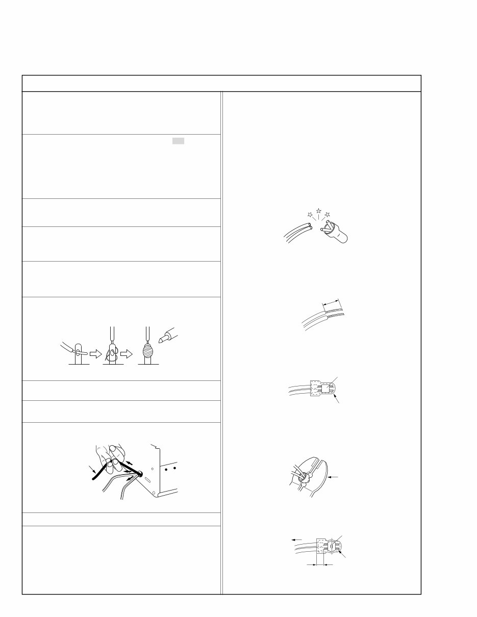
6. When replacing AC primary side components (transformers, power
cords, noise blocking capacitors, etc.) wrap ends of wires securely
about the terminals before soldering.
Power cord
Fig.2
10. Also check areas surrounding repaired locations.
11. Products using cathode ray tubes (CRTs)
In regard to such products, the cathode ray tubes themselves, the
high voltage circuits, and related circuits are specified for compli-
ance with recognized codes pertaining to X-ray emission.
Consequently, when servicing these products, replace the cath-
ode ray tubes and other parts with only the specified parts. Under
no circumstances attempt to modify these circuits.
Unauthorized modification can increase the high voltage value and
cause X-ray emission from the cathode ray tube.
12. Crimp type wire connector
In such cases as when replacing the power transformer in sets
where the connections between the power cord and power trans-
former primary lead wires are performed using crimp type connec-
tors, if replacing the connectors is unavoidable, in order to prevent
safety hazards, perform carefully and precisely according to the
following steps.
1) Connector part number : E03830-001
2) Required tool : Connector crimping tool of the proper type which
will not damage insulated parts.
3) Replacement procedure
(1) Remove the old connector by cutting the wires at a point
close to the connector.
Important : Do not reuse a connector (discard it).
Fig.7
cut close to connector
Fig.3
(2) Strip about 15 mm of the insulation from the ends of the
wires. If the wires are stranded, twist the strands to avoid
frayed conductors.
15 mm
Fig.4
(3) Align the lengths of the wires to be connected. Insert the
wires fully into the connector.
Connector
Metal sleeve
Fig.5
(4) As shown in Fig.6, use the crimping tool to crimp the metal
sleeve at the center position. Be sure to crimp fully to the
complete closure of the tool.
I
•
Precautions during Servicing
7. Observe that wires do not contact heat producing parts (heatsinks,
oxide metal film resistors, fusible resistors, etc.)
8. Check that replaced wires do not contact sharp edged or pointed
parts.
9. When a power cord has been replaced, check that 10-15 kg of
force in any direction will not loosen it.
1.25
2.0
5.5
Crimping tool
Fig.6
(5) Check the four points noted in Fig.7.
Not easily pulled free
Crimped at approx. center
of metal sleeve
Conductors extended
Wire insulation recessed
more than 4 mm
S40888-01
•
Safety Check after Servicing
Examine the area surrounding the repaired location for damage or deterioration. Observe that screws, parts and wires have been returned
to original positions, Afterwards, perform the following tests and confirm the specified values in order to verify compliance with safety
standards.
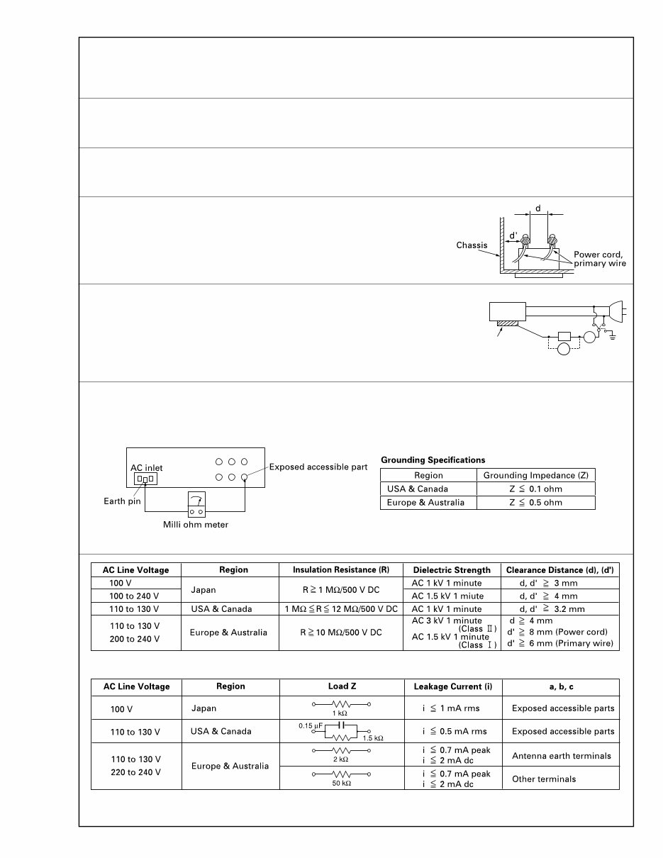
1. Insulation resistance test
Confirm the specified insulation resistance or greater between power cord plug prongs and exter-
nally exposed parts of the set (RF terminals, antenna terminals, video and audio input and output
terminals, microphone jacks, earphone jacks, etc.). See table 1 below.
2. Dielectric strength test
Confirm specified dielectric strength or greater between power cord plug prongs and exposed acces-
sible parts of the set (RF terminals, antenna terminals, video and audio input and output terminals,
microphone jacks, earphone jacks, etc.). See table 1 below.
3. Clearance distance
When replacing primary circuit components, confirm specified clearance distance (d), (d’) be-
tween soldered terminals, and between terminals and surrounding metallic parts. See table 1
below.
4. Leakage current test
Confirm specified or lower leakage current between earth ground/power cord plug prongs and
externally exposed accessible parts (RF terminals, antenna terminals, video and audio input and
output terminals, microphone jacks, earphone jacks, etc.).
Measuring Method : (Power ON)
Insert load Z between earth ground/power cord plug prongs and externally exposed accessible
parts. Use an AC voltmeter to measure across both terminals of load Z. See figure 9 and following
table 2.
5. Grounding (Class 1 model only)
Confirm specified or lower grounding impedance between earth pin in AC inlet and externally exposed accessible parts (Video in, Video out,
Audio in, Audio out or Fixing screw etc.).
Measuring Method:
Connect milli ohm meter between earth pin in AC inlet and exposed accessible parts. See figure 10 and grounding specifications.
Fig. 10
Fig. 9
Fig. 8
Table 1 Specifications for each region
Table 2 Leakage current specifications for each region
Note: These tables are unofficial and for reference only. Be sure to confirm the precise values for your particular country and locality.
II
S40888-01
a b
c
V
A
Externally
exposed
accessible part
Z

1-1
SECTION 1
DISASSEMBLY
1.1 HOW TO REMOVE THE MAJOR PARTS
1.1.1 Introduction
This set is a double-deck video recorder integrating a Mini DV
deck and a VHS deck. Its internal structure is divided into three
sections that include the power supply, VHS and DV sections.
Therefore, the removal of major parts will also be described
under three separate sections as listed below.
1. COMMON section
2. VHS section
3. DV section
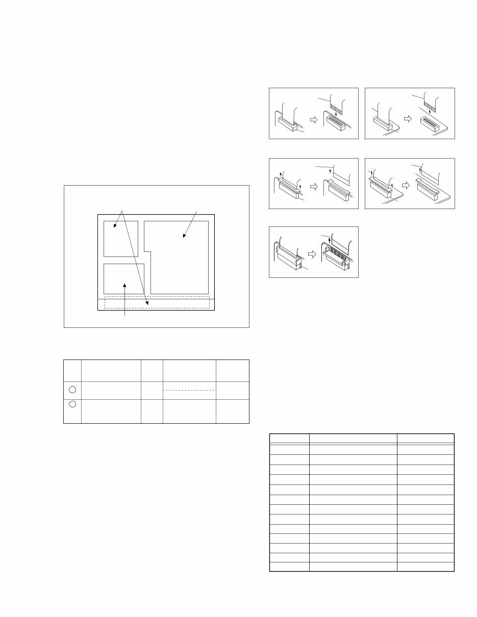
1.2 HOW TO READ THE DISASSEMBLY AND ASSEMBLY
3. DV section
1. COMMON section 2. VHS section
< TOP VIEW >
(1) Order of steps in Procedure
When reassembling, perform the step(s) in the reverse order.
These numbers are also used as the identification (location) No.
of parts Figures.
(2) Part name to be removed or installed.
(3) Fig. No. showing procedure or part location.
(4) Identification of part to be removed, unhooked, unlocked,
released, unplugged, unclamped or unsoldered.
P= Spring, W= Washer, S= Screw, L= Locking tab, SD= Solder,
CN**(WR**)= Remove the wire (WR**) from the connector
(CN**).
Note:
• The bracketed ( ) WR of the connector symbol are as-
signed nos. in priority order and do not correspond to
those on the spare parts list.
(5) Adjustment information for installation
Fig. 1-1-1
§ § § § §
(1) (2) (3) (4) (5)
Step/
Loc No.
Fig. No. Point Note Part name
Top cover, Bracket COM1
4(S1), 3(S2), 2(L1), (L2)
2(S3)
1 —
Front panel
assembly
COM2 8(L3),
CN7507(WR1),
CN3011(WR2)
<Note
1,2,3,4>
2
1.3 DISCONNECTION OF CONNECTORS (WIRES)
CONNECTOR
FPC
CONNECTOR
FPC
Fig. 1-3-1 Fig. 1-3-2
Fig. 1-3-3 Fig. 1-3-4
CONNECTOR
FPC
Fig. 1-3-5
CONNECTOR
FPC
CONNECTOR
FPC
1.4 SCREWS USED CABINET COMPONENTS AND
BOARD ASSEMBLIES
Table 1-4-1 below shows the symbols, shapes, colors and
part numbers of screw that are used in the cabinet compo-
nents and board assemblies and are appearing in the disas-
sembling/reassembling diagrams in this manual.
When screwing them again in reassembling, be sure to use
them correctly referring to the following table.
Notes:
• Screw that are asterisked (marked with*) in the shape col-
umn are fixed with screw lock agent. If such the screw is
once removed, never use it again.
• The Screw symbols are assigned nos. in priority order and
do not correspond to those on the spare parts list.
SYMBOL PARTS NO. COLOR
S1 QYTDST3006R SILVER BLACK
S4 QYTDSF2606Z GOLD
S8 PQ21623-2-5 GOLD
S5 QYTDST3006Z GOLD
S2 QYTDST3006M BLACK
S6 QYTDSF3008M BLACK
S3 QYTDSF3010Z GOLD
S7 QYTDST2610Z GOLD
S11 QYTDSP2004Z GOLD
S12 QYTDST2004Z GOLD
S13 YQ43893 SILVER
S9 PQ40413 BLACK
S10 LP40700-001A BLACK
Table 1-4-1
1-2
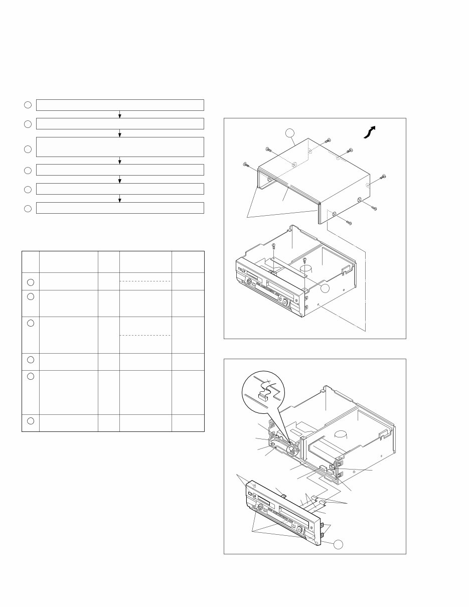
1.5 HOW TO REMOVE THE MAJOR PARTS <COM section>
1.5.1 Disassembly flow chart
This flowchart shows the disassembly procedure for the ex-
terior parts and electrical parts.
Basically, reverse this procedure when assembling them.
1 Top cover, Bracket
2 Front panel assembly
Display board assembly, Display/SW board assembly,
3
SW board assembly, LED1, 2 board assembly
4 SW REG board assembly
5 Regulator board assembly
6 Rear cover
<Note 1>
When attaching the FPC, be sure to connect it in the cor-
rect orientation.
<Note 2>
When attaching the front panel assy, make sure that the
door openers of both decks (DV, VHS) are in the down
position.
<Note 3>
When attaching the front panel assy, be careful not to dam-
age the DV terminals.
<Note 4>
When attaching the FPC take care that it is not caught.
Pass the DV-side FPC between the base (2) and DV Main
board assy.
Pass the two VHS-side FPCs below the base (1).
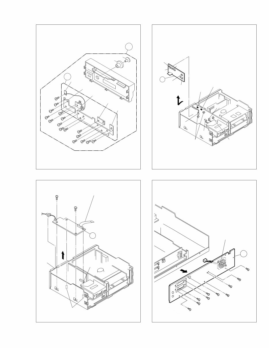
1.5.2 Disassembly/assembly method <COM section>
<Note 5>
When removing the SW REG board assembly or Regula-
tor board assembly, unhook the several spacers connect-
ing it with pliers from the top side.
<Note 6>
Perform the work by leaving fan motor attached to the rear
cover except when replacing the fan motor.
When attaching the rear cover, please be careful with the
wiring.
Fig. COM1
Top cover
7
(S2)
5
(S2)
4
(S1)
3
(S1)
6
(S2)
2
(S1)
1
(S1)
1
(L1)
(L2)
1
8
(S3)
9
(S3)
Bracket
(L3)
(L3)
<Note 4>
FPC
DV Main board
assembly
WR2
WR1
<Note 4>
<Note 1>
Supporting
tape side
<Note 2>
DV SIDE
<Note 2>
VHS SIDE
Base (2)
Base (1)
<Note 3>
CN7507
CN3011
2
(L3)
(L3)
Fig. COM2
Step/
Loc No.
Fig. No. Point Note Part name
Top cover, Bracket COM1
4(S1), 3(S2), 2(L1), (L2)
2(S3)
1 —
—
Front panel
assembly
COM2 8(L3),
CN7507(WR1),
CN3011(WR2)
<Note
1,2,3,4>
<Note 1,
5>
2
SW REG board
assembly
4
COM3 10(S4)
6(S4), Knob(Jog),
Knob(Shuttle),
3
Display board assembly,
LED/SW board assembly,
Eject SW board assembly,
Jack board assembly,
Jog board assembly
COM4 2(S5), 2(L4), (L5)
CN5301(WR3),
<Note 1,
5>
Regulator board
assembly
5
COM5 3(L6),
CN5322(WR4),
CN5321(WR5),
CN5325(WR6),
CN5324(WR7),
CN5323(WR8)
<NOTE 6> Rear cover
6
COM6 4(S2), 6(S6),
Fan motor
1-3
Fig. COM3
Fig. COM4
Fig. COM5
Fig. COM6
<Note 6>
Fan Motor
6
28
(S2)
29
(S2)
33
(S6)
32
(S6)
35
(S6)
34
(S6)
36
(S6)
37
(S6)
30
(S2)
31
(S2)
9
(S4)
20
(S4)
22
(S4)
24
(S4)
25
(S4)
16
(S4)
15
(S4) 14
(S4)
18
(S4)
13
(S4)
17
(S4)
12
(S4)
11
(S4)
10
(S4)
23
(S4)
23
(S4)
21
(S4)
Display board
assembly
LED/SW board
assembly
Jog board assembly
Jack board
assembly
Eject SW
board assembly
Knob (Jog)
Knob (Shuttle)
3
2
5
CN5325
CN5324
WR8
WR5
Foil side
<Note 1>
WR4
Foil side
<Note 1>
WR6
WR7
CN5321
CN5322
(L6)
Spacer
<Note 5>
(L6)
Spacer
<Note 5>
CN5323
4
27
(S5)
WR3
Supporting
tape side
<Note 1>
(L4)
Spacer
<Note 5>
(L5)
CN5301
26
(S5)
1-4
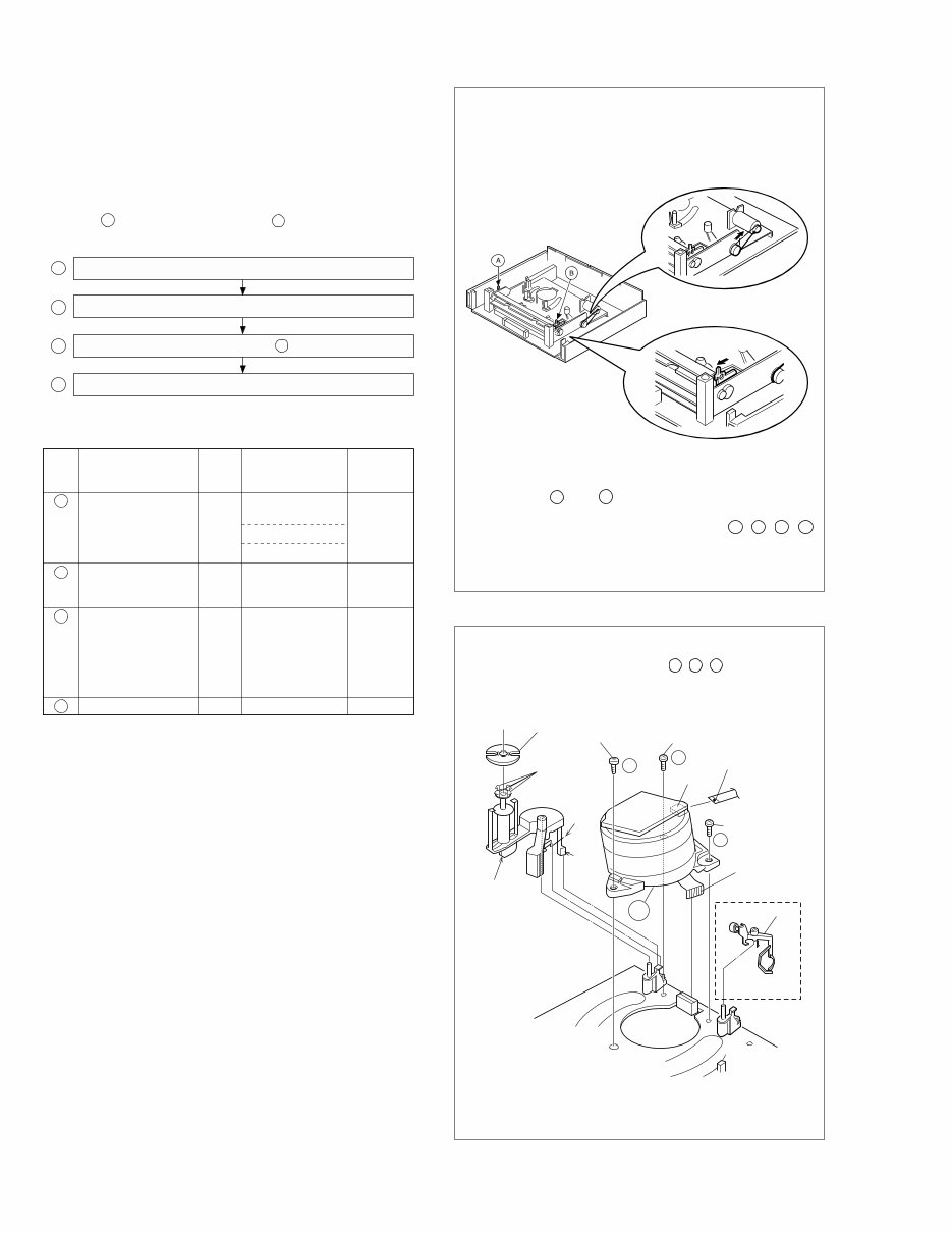
1.6 HOW TO REMOVE THE MAJOR PARTS <VHS section>
1.6.1 Disassembly flow chart
This flowchart shows the disassembly procedure for the ex-
terior parts and electrical parts.
Basically, reverse this procedure when assembling them.
However, it is required to remove the common section parts
as far as 1 “Top cover Bracket” and 2 “Front panel assem-
bly” in advance. (See section 1.5.)
1 Drum assembly
2 Mechanism assembly
3 Main board assembly / 4 Base (1)
4 Base (1)
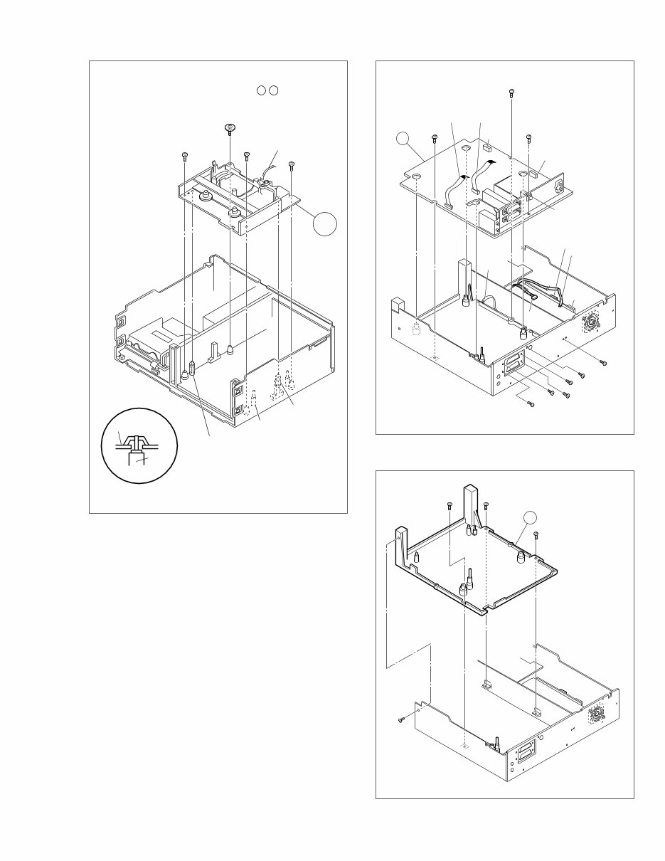
1.6.2 DIsassembly/assembly method <VHS section>
<Note 1>
When attaching or removing the FPC, take care not to dis-
connect any of the wires.
<Note 2>
When attaching the FPC, be sure to connect it in the cor-
rect orientation.
<Note 3>
When attaching wires, connect them in the correct orien-
tation.
<Note 4>
• When it is required to remove the screws (S8) retaining the
Mechanism assembly, please refer to the “Procedures for
Lowering the Cassette holder assembly”(See on page 1-5).
• When removing the Mechanism assembly only, unhook the
two spacers connecting it with the Main board assembly with
pliers from the back side of the Main board assembly first,
and then remove the Mechanism assembly.
• When reattaching the Mechanism assembly to the Main
board assembly, take care not to damage the sensors on
the Main board assembly (D3001: LED, Q3002: Start sen-
sor, Q3003: End sensor, S3002: S cassette switch).
Fig. 1
Fig. 2
Fig. 3
Procedures for Lowering the Cassette holder assembly
As the mechanism of this unit is integrated with the Housing
assembly, the holder must be lowered and the two screws un-
screwed when removing the Mechanism assembly.
Procedures for Lowering the Cassette holder assembly
Turn the loading motor pulley in the direction as indicated by
Fig.2. As both A and B levers are lodged twice, push the
levers in the direction as indicated by Fig.3 to release them.
When pushing the levers, do it in the order of A , B , B , A .
When the holder has been lowered, turn the pulley until the
cassette holder is securely in place without allowing any up/
down movement.
Fig. V1
1
CN1
a
c
CON1
b
WR9
Foil side
<Note 2>
(L1)
(L2)
(P1)
Roller arm
assy
Inertia plate
WR10
Foil side
<Note 1,2>
Cleaner assy
Not use
1
(S7)
3
(S7)
2
(S7)
Note: When installing the Drum assembly, secure the
screws (S7) in the order of a , b , c .
Step/
Loc No.
Fig. No. Point Note Part name
Drum assembly
(Inertia plate)
(Roller arm assy)
V1 3(S7), CON1(WR9),
CN1(WR10)
4(L1)
(P1), (L2)
1 <Note 1,2>
Mechanism
assembly
V2 2(S8), (S9), (S10),
(L3), (L4),
CN1(WR11),
2 <Note 2,4>
Main board
assembly
V3 6(S6), 2(S3), (S5),
CN5321(WR12),
CN5322(WR13),
CN3014(WR14),
CN703(WR15),
CN2601(WR16)
3 <Note 2>
Base (1) V4 (S3), 3(S5) 4 —
1-5
Fig. V2
Fig. V3
<Note 4>
Spacer
Mechanism assy
(L3)
Spacer
<Note 4>
S3002
S cassette switch
<Note 4>
(L4)
Spacer
<Note 4>
5
(S8)
<Note 4>
4
(S8)
<Note 4>
WR11
Foil side
<Note 2>
6
(S9)
7
(S10)
2
14
(S3)
16
(S5)
15
(S3)
9
(S6)
8
(S6)
11
(S6)
10
(S6)
12
(S6)
13
(S6)
WR14
Foil side
<Note 2>
CN5322
CN703
WR13
CN2601
CN3014
WR4
Foil side
<Note 2>
WR5
Foil side
<Note 2>
WR12
Foil side
<Note 2>
CN5321
3
Fig. V4
17
(S3)
18
(S5)
19
(S5)
20
(S5)
4
Note: When installing the Mechanism assembly, secure
the screws (S8) in the order of a , b .
You're Reading a Preview
What's Included?
Fast Download Speeds
Online & Offline Access
Access PDF Contents & Bookmarks
Full Search Facility
Print one or all pages of your manual
$28.99
Viewed 70 Times Today


Secure transaction
What's Included?
Fast Download Speeds
Online & Offline Access
Access PDF Contents & Bookmarks
Full Search Facility
Print one or all pages of your manual
$28.99
The JVC HR-DVS2EA Service Manual is an essential resource for anyone involved in car repair and maintenance. This comprehensive manual provides detailed technical information, diagrams, and instructions for servicing and repairing the JVC HR-DVS2EA model. Whether you are a professional mechanic or a DIY enthusiast, this manual equips you with the knowledge needed to effectively troubleshoot and fix issues with the JVC HR-DVS2EA. With its clear and concise documentation, this manual is an invaluable tool for ensuring the optimal performance and longevity of the JVC HR-DVS2EA.


