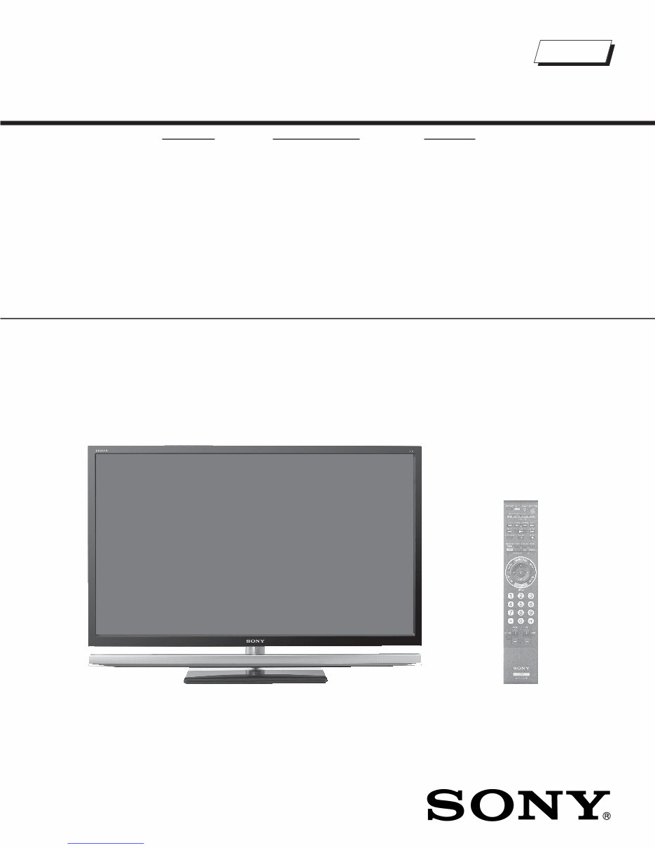
LCD DIGITAL COLOR TELEVISION SERVICE MANUAL EX1 CHASSIS MODEL NAME REMOTE COMMANDER DESTINATION 9-883-802-01 KDL-40XBR6 RM-YD024 US/CND KDL-40XBR6 RM-YD024 MX/LATIN AMERICA KDL-46XBR6 RM-YD024 US/CND KDL-46XBR6 RM-YD024 MX/LATIN AMERICA KDL-52XBR6 RM-YD024 US/CND KDL-52XBR6 RM-YD024 MX/LATIN AMERICA HISTORY INFORMATION FOR THE FOLLOWING MANUAL: ORIGINAL MANUAL ISSUE DATE: 8/2008 REVISION DATE SUBJECT 8/2008 No revisions or updates are applicable at this time. Downloaded from www.Manualslib.com manuals search engine
LCD DIGITAL COLOR TELEVISION SERVICE MANUAL EX1 CHASSIS MODEL NAME REMOTE COMMANDER DESTINATION 9-883-802-01 KDL-40XBR6 RM-YD024 US/CND KDL-40XBR6 RM-YD024 MX/LATIN AMERICA KDL-46XBR6 RM-YD024 US/CND KDL-46XBR6 RM-YD024 MX/LATIN AMERICA KDL-52XBR6 RM-YD024 US/CND KDL-52XBR6 RM-YD024 MX/LATIN AMERICA Self Diagnosis Supported model KDL-46XBR6 RM-YD024 Downloaded from www.Manualslib.com manuals search engine
3 KDL-40XBR6/46XBR6/52XBR6 KDL-40XBR6/46XBR6/52XBR6 TABLE OF CONTENTS SECTION TITLE PAGE SECTION TITLE PAGE Specifications ................................................................................. 4 Warnings and Cautions - English ................................................... 6 Warnings and Cautions - French .................................................... 7 Safety-Related Component Warning .............................................. 8 Safety Check-Out ......................................................................... 10 Self-Diagnostic Function................................................................ 11 SECTION 1: DISASSEMBLY............................................................... 13 1-1. Rear Cover and Switch Unit (Contains H1 Board) Removal 13 1-1-1. KDL-40XBR6/46XBR6 Only .................................... 13 1-1-2. KDL-52XBR6 Only ................................................... 13 1-2. Woofer Box Removal ........................................................... 14 1-2-1. KDL-40XBR6/46XBR6 Only .................................... 14 1-2-2. KDL-52XBR Only ..................................................... 14 1-3. AWF Board, BU Board, G Board and D Board Removal ..... 15 1-3-1. KDL-40XBR6/46XBR6 Only .................................... 15 1-3-2. KDL-52XBR6 Only ................................................... 15 1-4. Table-Top Stand and Under Cover Removal........................ 16 1-5. Structural Frames, Brackets and AC Inlet Removal ............. 17 1-5-1. KDL-40XBR6/46XBR6 Only .................................... 17 1-5-2. KDL-52XBR6 Only ................................................... 18 1-6. Speaker Cover and Speaker Box Removal ........................ 19 1-7. H3R Board and H4R Board Removal .................................. 20 1-8. LCD Panel, Illumination Module and Logo Holder Removal 20 1-8-1. Cleaning the LCD Panel .......................................... 20 1-9. Inverter Board Removal ....................................................... 21 1-9-1. KDL-40XBR6/46XBR6 Only .................................... 21 1-9-2. KDL-52XBR6 Only ................................................... 22 WIRE DRESSING ........................................................................ 23 SECTION 2: SERVICE ADJUSTMENTS ............................................. 24 2-1. Viewing Service Adjustment Data ........................................ 24 2-2. Accessing Service Adjustment Mode ................................... 24 2-3. Viewing the Service Menus .................................................. 24 2-4. Using the Remote Commander to View Service Data ......... 25 2-5. Resetting to Factory Defaults ............................................... 25 SECTION 3: DIAGRAMS ..................................................................... 26 3-1. Circuit Boards Location ........................................................ 26 3-2. Printed Wiring Boards and Schematic Diagrams Information ......................................... 26 3-3. Block Diagram ...................................................................... 28 3-4. Schematics and Supporting Information .............................. 29 AWF Board Schematic Diagram .......................................... 29 BU Board Schematic Diagram (1 of 12) ............................... 32 BU Board Schematic Diagram (2 of 12) ............................... 33 BU Board Schematic Diagram (3 of 12) ............................... 34 BU Board Schematic Diagram (4 of 12) ............................... 35 BU Board Schematic Diagram (5 of 12) ............................... 36 BU Board Schematic Diagram (6 of 12) ............................... 37 BU Board Schematic Diagram (7 of 12) ............................... 38 BU Board Schematic Diagram (8 of 12) ............................... 39 BU Board Schematic Diagram (9 of 12) ............................... 40 BU Board Schematic Diagram (10 of 12) ............................. 41 BU Board Schematic Diagram (11 of 12) ............................. 42 BU Board Schematic Diagram (12 of 12) ............................. 43 D3 Board Schematic Diagram (KDL-40XBR6/46XBR6 Only) .................................. 45 D4 Board Schematic Diagram (KDL-52XBR6 Only) ............ 47 D5 Board Schematic Diagram (KDL-52XBR6 Only) ............ 49 G5 Board Schematic Diagram (KDL-52XBR6 Only) ............ 51 G6 Board Schematic Diagram (1 of 2) (KDL-40XBR6/46XBR6 Only) ................................. 54 G6 Board Schematic Diagram (2 of 2) (KDL-40XBR6/46XBR6 Only) ................................. 55 H3R Board Schematic Diagram ........................................... 58 H4R Board Schematic Diagram ........................................... 60 3-5. Semiconductors ................................................................... 62 SECTION 4: EXPLODED VIEWS ........................................................ 63 4-1. Rear Cover Assembly and Table-Top Assembly ................. 63 4-2. Chassis (KDL-40XBR6/46XBR6 Only)................................. 64 4-3. Chassis (KDL-52XBR6 Only) ............................................... 65 4-4. Connectors (KDL-40XBR6/46XBR6 Only) ........................... 66 4-5. Connectors (KDL-52XBR6 Only) ......................................... 67 4-6. Bezel Assembly and LCD Panel (KDL-40XBR6/46XBR6 Only) .............................................. 68 4-7. Bezel Assembly and LCD Panel (KDL-52XBR6 Only) ......... 69 4-5. Screw Legend ...................................................................... 70 SECTION 5: ELECTRICAL PARTS LIST ............................................ 71 APPENDIX A: ENCRYPTION KEY COMPONENTS .......................... A-1 Downloaded from www.Manualslib.com manuals search engine
4 KDL-40XBR6/46XBR6/52XBR6 KDL-40XBR6/46XBR6/52XBR6 SPECIFICATIONS Design and specifications are subject to change without notice. 120V AC, 60Hz 225W (KDL-40XBR6 Only) 285W (KDL-46XBR6 Only) 295W (KDL-52XBR6 Only) Less than 0.2W VIDEO (IN) 1/2/3: S Video (4-Pin Mini DIN (VIDEO 1 Only) Y: 1.0 Vp-p, 75 ohms unbalanced, sync negative C: 0.286 Vp-p (Burst signal), 75 ohms Video 1.0 Vp-p, 75 ohms unbalanced, sync negative Audio 500 mVrms (Typical) Impedance:47 kilohms COMPONENT IN 1/2: YP B P R (Component Video) Y:1.0 Vp-p, 75 ohms unbalanced, sync negative P B :0.7 Vp-p, 75 ohms P R :0.7 Vp-p, 75 ohms Signal format: 480i, 480p, 720p, 1080i, 1080p AUDIO 500 mVrms (Typical) Impedance: 47 kilohms Power Requirements Power Consumption (W) In Use (Max) In Standby HDMI IN 1/2/3/4: HDMI: Video: 480i, 480p, 720p, 1080i,1080p, 1080/24p Audio: Two channel linear PCM 32, 44.1 and 48 kHz, 16, 20 and 24 bits, Dolby Digital AUDIO (for HDMI IN 4): 500 mVrms (Typical) (Fixed) Impedance: 47 kilohms AUDIO OUT: 500 mVrms (Typical) DIGITAL AUDIO OUT (OPTICAL): PCM/Dolby Digital optical signal PC IN: D-sub 15-pin, analog RGB, 0.7 Vp-p, 75 ohms, positive PC AUDIO INPUT: Stereo mini jack, 500 mVrms (Typical) Impedance: 47 kilohms LAN (10/100): 10 BASE-T/100 BASE-TX Connector DMPORT: VIDEO: 1.0 Vp-p, 75 ohms unbalanced, sync negative AUDIO: 500 mVrms (Typical)/Impedance: 47 kilohms USB: Hi-Speed USB Downloaded from www.Manualslib.com manuals search engine
5 KDL-40XBR6/46XBR6/52XBR6 KDL-40XBR6/46XBR6/52XBR6 Television system NTSC American TV Standard ATSC (8VSB terrestrial) ATSC compliant 8VSB QAM on cable ANSI/SCTE 07 2000 Channel coverage Analog 2-69 Terrestrial 1-135 Cable Digital 2-69 Terrestrial 1-135 Cable Antenna 75-ohm external terminal for RF inputs Panel System LCD (Liquid Crystal Display) Panel Display Resolution (horizontal x vertical) 1,920 dots x 1,080 lines Screen Size (measured diagonally) approx. 40 inches (KDL-40XBR6 Only) approx. 46 inches (KDL-46XBR6 Only) approx. 52 inches (KDL-52XBR6 Only) Supplied Accessories Remote Commander RM-YD024 Two Size AA (R6) Batteries AC Power Cord Cable Holder (1 attached to the TV) Operating Instructions Quick Setup Guide Warranty Card Safety and Regulatory Booklet Attaching the Table-Top Stand (KDL-40XBR6/46XBR6 Only) Screws (4) (KDL-40XBR6/46XBR6 Only) Optional Accessories Connecting Cables Suport Belt Kit Colour Variation Unit Wall-Mount Bracket SU-WL500 TV-Stand WS-S10LS SU-FL71M (KDL-40XBR6/46XBR6 Only) Speaker/Front (2) mm in Tweater (2) mm in Assist Woofer mm 55 x 120 in 2 1/8 x 4 3/4 Dimensions (W x H x D) with stand mm 983 x 684 x 279 mm 1,089 x 765 x 307 mm 1,257 x 874 x 346 mm in 37 5/8 x 27 x 11 in 42 7/8 x 30 1/8 x 12 1/8 in 49 1/2 x 34 1/2 x 13 5/8 in without stand mm 953 x 645 x 103 mm 1,089 x 723 x 104 mm 1,257 x 831 x 127 mm in 37 5/8 x 25 1/2 x 4 1/8 in 42 7/8 x 28 1/2 x 4 1/8 in 49 1/2 x 32 3/4 x 5 in wall-mount hole pattern (mm) Mass with stand kg 23.5 kg 28 kg 42.5 kg lbs 52 lbs 62 lbs 94 lbs without stand kg 20 kg 23.5 kg 35.5 kg lbs 45 lbs 52 lbs 79 lbs All measurements are approximations. wall-mount screw size (mm) KDL-52XBR6 KDL-46XBR6 KDL-40XBR6 300 x 300 mm 8W(L)+8W(R)+11W (Assist Woofer) 10W(L)+10W(R)+15W (Assist Woofer) Speaker Output M6 X 8 -12 50 x 100 2 x 4 34 x 104 1 3/8 x 4 1/8 30 1 1/8 x 1 Downloaded from www.Manualslib.com manuals search engine
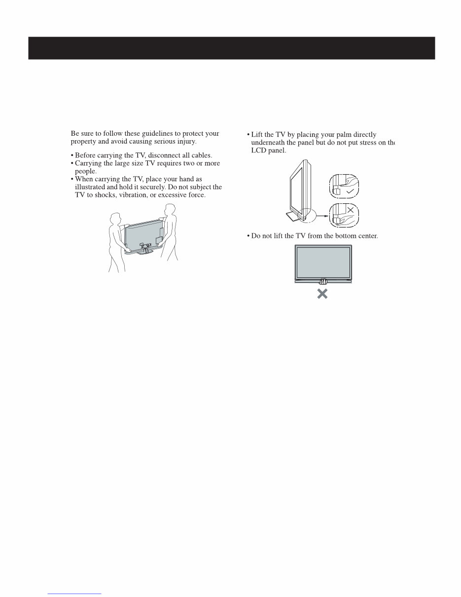
6 KDL-40XBR6/46XBR6/52XBR6 KDL-40XBR6/46XBR6/52XBR6 WARNINGS AND CAUTIONS - ENGLISH CAUTION These servicing instructions are for use by qualified service personnel only. To reduce the risk of electric shock, do not perform any servicing other than that contained in the operating instructions unless you are qualified to do so. CARRYING THE TV WARNING!! An isolation transformer should be used during any service to avoid possible shock hazard, because of live chassis. The chassis of this receiver is directly connected to the ac power line. ! SAFETY-RELATED COMPONENT WARNING!! Components identified by shading and ! mark on the schematic diagrams, exploded views, and in the parts list are critical for safe operation. Replace these components with Sony parts whose part numbers appear as shown in this manual or in supplements published by Sony. Circuit adjustments that are critical for safe operation are identified in this manual. Follow these procedures whenever critical components are replaced or improper operation is suspected. Downloaded from www.Manualslib.com manuals search engine
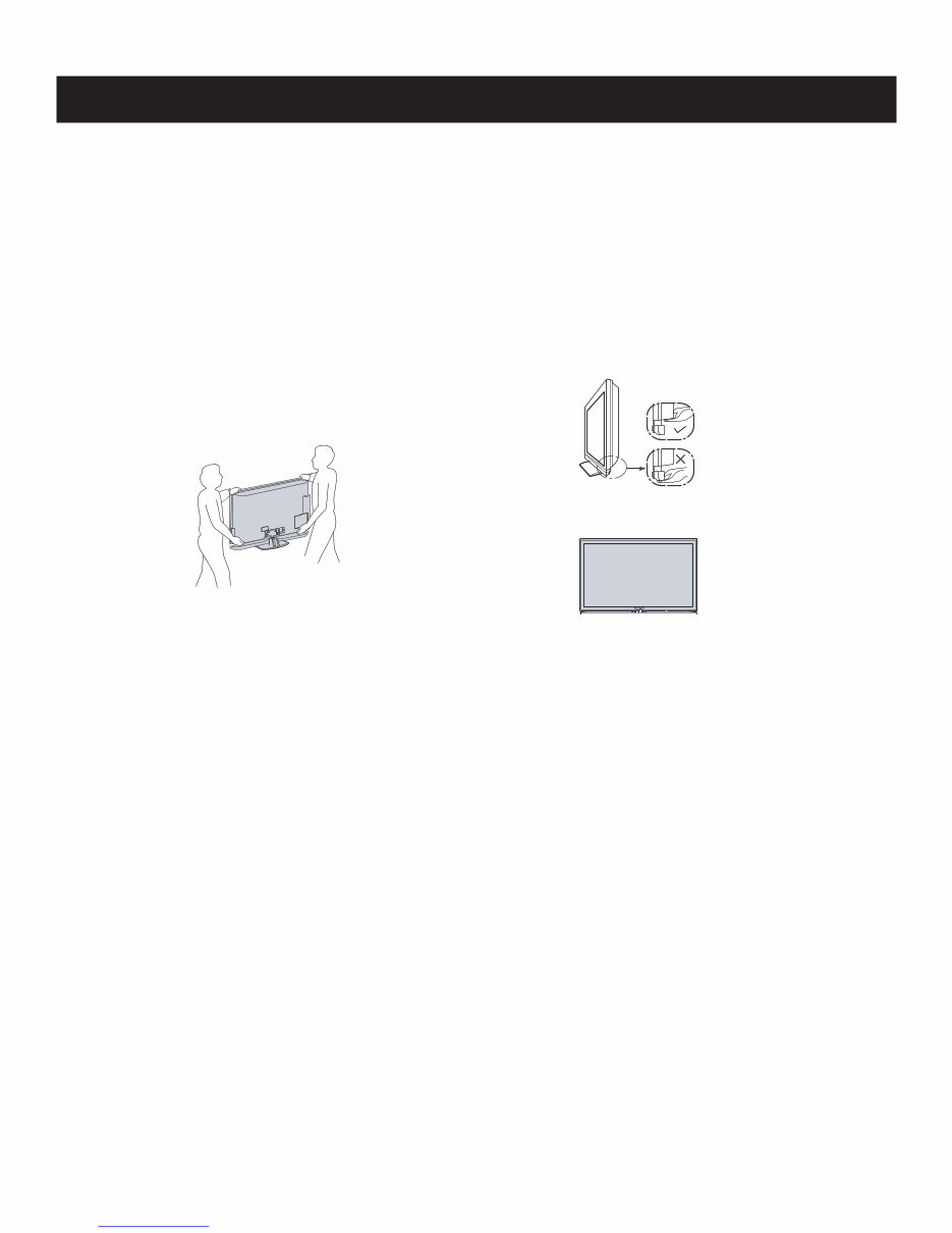
7 KDL-40XBR6/46XBR6/52XBR6 KDL-40XBR6/46XBR6/52XBR6 WARNINGS AND CAUTIONS - FRENCH ATTENTION!! Ces instructions de service sont à l’usage du personnel de service qualifié seulement. Pour prévenir le risque de choc électrique, ne pas faire l’entretien autre que celui contenu dans le Mode d’emploi à moins que vous soyez qualifié faire ainsi. POUR TRANSPORTER LE TÉLÉVISEUR Assurez-vous de suivre les consignes suivantes pour protéger votre bien et éviter les blessures graves. • Avant de transporter le téléviseur, débranchez tous les câbles. • Le transport d’un téléviseur de grande taille doit être effectué par au moins deux personnes. • Lorsque vous transportez le téléviseur, placez vos mains tel qu’illustré et tenez solidement l’appareil. Ne soumettez pas le téléviseur à des chocs ou à des vibrations, ni à une force excessive. • Soulevez le téléviseur en plaçant la paume de votre main directement en dessous du panneau, mais : • n’appuyez pas sur la région de la grille de haut-parleur • ne placez pas vos doigts dans le sillon au- dessus de la région de la grille de haut-parleur • n’imposez pas de charge sur le panneau ACL. • ne soulevez pas le téléviseur en plaçant vos mains en dessous au centre. Afin d’eviter tout risque d’electrocution provenant d’un chássis sous tension, un transformateur d’isolement doit etre utilisé lors de tout dépannage. Le chássis de ce récepteur est directement raccordé à l’alimentation du secteur. ! ATTENTION AUX COMPOSANTS RELATIFS A LA SECURITE!! Les composants identifies par une trame et par une marque ! sur les schemas de principe, les vues explosees et les listes de pieces sont d’une importance critique pour la securite du fonctionnement. Ne les remplacer que par des composants Sony dont le numero de piece est indique dans le present manuel ou dans des supplements publies par Sony. Les reglages de circuit dont l’importance est critique pour la securite du fonctionnement sont identifies dans le present manuel. Suivre ces procedures lors de chaque remplacement de composants critiques, ou lorsqu’un mauvais fonctionnement suspecte. Downloaded from www.Manualslib.com manuals search engine
8 KDL-40XBR6/46XBR6/52XBR6 KDL-40XBR6/46XBR6/52XBR6 SAFETY-RELATED COMPONENT WARNING There are critical components used in LCD color TVs that are important for safety. These components are identified with shading and ! mark on the schematic diagrams and the electrical parts list. It is essential that these critical parts be replaced only with the part number specified in the electrical parts list to prevent electric shock, fire, or other hazard. NOTE: Do not modify the original design without obtaining written permission from the manufacturer or you will void the original parts and labor guarantee. USE CAUTION WHEN HANDLING THE LCD PANEL When repairing the LCD panel, be sure you are grounded by using a wrist band. When installing the LCD panel on a wall, the LCD panel must be secured using the 4 mounting holes on the rear cover. To avoid damaging the LCD panel: do not press on the panel or frame edge to avoid the risk of electric shock. do not scratch or press on the panel with any sharp objects. do not leave the module in high temperatures or in areas of high humidity for an extended period of time. do not expose the LCD panel to direct sunlight. avoid contact with water. It may cause a short circuit within the module. disconnect the AC adapter when replacing the backlight (CCFL) or inverter circuit. (High voltage occurs at the inverter circuit at 650Vrms.) always clean the LCD panel with a soft cloth material. use care when handling the wires or connectors of the inverter circuit. Damaging the wires may cause a short. protect the panel from ESD to avoid damaging the electronic circuit (C-MOS). LEAKAGE CURRENT HOT CHECK CIRCUIT Downloaded from www.Manualslib.com manuals search engine
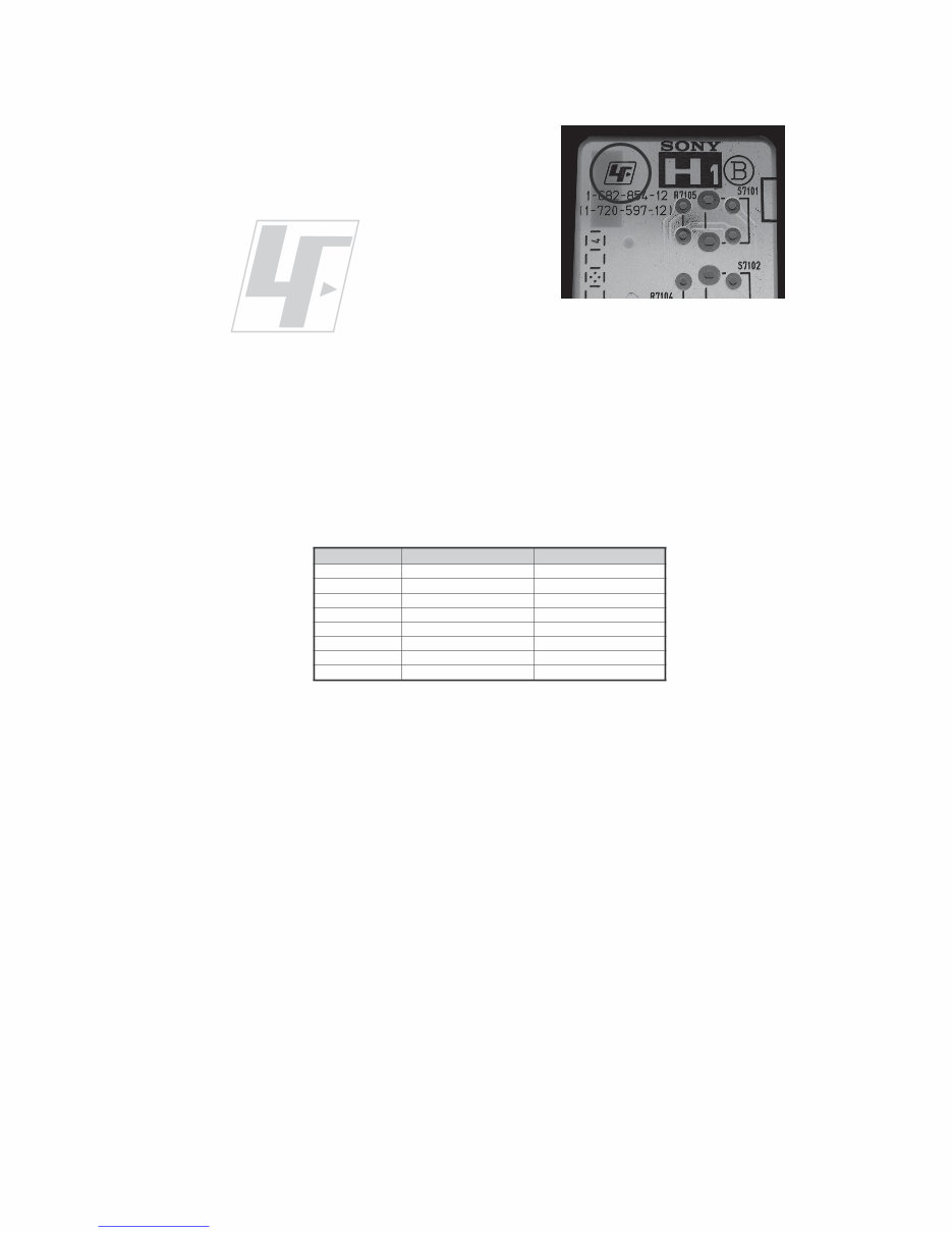
9 KDL-40XBR6/46XBR6/52XBR6 KDL-40XBR6/46XBR6/52XBR6 The circuit boards used in these models have been processed using Lead Free Solder. The boards are identified by the LF logo located close to the board designation e.g. H1 etc [ see example ]. The servicing of these boards requires special precautions to be taken as outlined below. example 1 It is strongly recommended to use Lead Free Solder material in order to guarantee optimal quality of new solder joints. Lead Free Solder is available under the following part numbers : Due to the higher melting point of Lead Free Solder the soldering iron tip temperature needs to be set to 370 degrees centigrade. This requires soldering equipment capable of accurate temperature control coupled with a good heat recovery characteristics. For more information on the use of Lead Free Solder, please refer to http://www.sony-training.com r e b m u n t r a P r e t e m a i D s k r a m e R 9 1 - 5 0 0 - 0 4 6 - 7 m m 3 . 0 g K 5 2 . 0 0 2 - 5 0 0 - 0 4 6 - 7 m m 4 . 0 g K 0 5 . 0 1 2 - 5 0 0 - 0 4 6 - 7 m m 5 . 0 g K 0 5 . 0 2 2 - 5 0 0 - 0 4 6 - 7 m m 6 . 0 g K 5 2 . 0 3 2 - 5 0 0 - 0 4 6 - 7 m m 8 . 0 g K 0 0 . 1 4 2 - 5 0 0 - 0 4 6 - 7 m m 0 . 1 g K 0 0 . 1 5 2 - 5 0 0 - 0 4 6 - 7 m m 2 . 1 g K 0 0 . 1 6 2 - 5 0 0 - 0 4 6 - 7 m m 6 . 1 g K 0 0 . 1 Downloaded from www.Manualslib.com manuals search engine
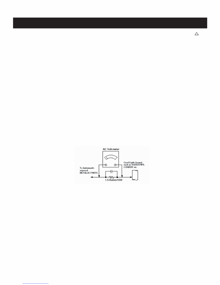
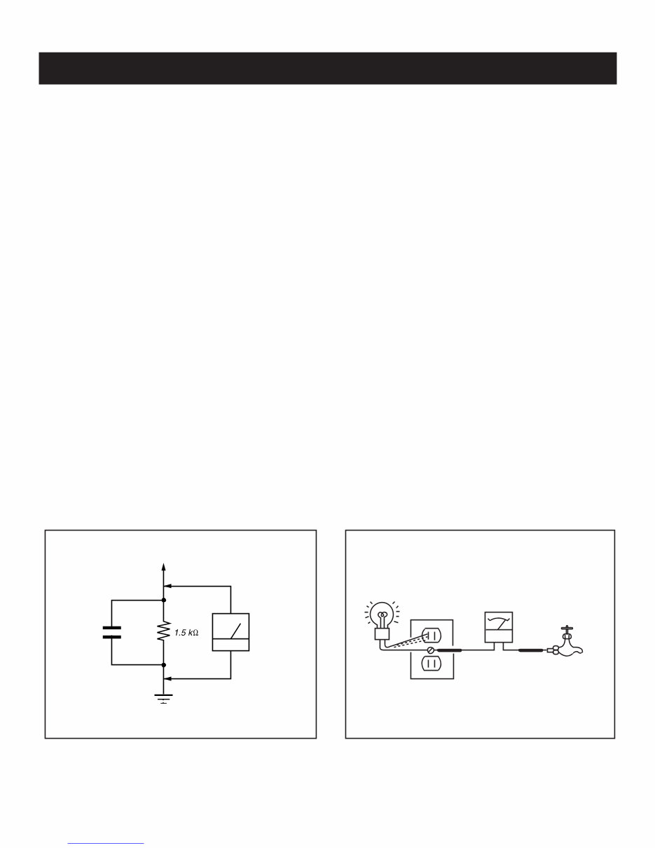
10 KDL-40XBR6/46XBR6/52XBR6 KDL-40XBR6/46XBR6/52XBR6 SAFETY CHECK-OUT After correcting the original service problem, perform the following safety checks before releasing the set to the customer: 1. Check the area of your repair for unsoldered or poorly soldered connections. Check the entire board surface for solder splashes and bridges. 2. Check the interboard wiring to ensure that no wires are “pinched” or touching high-wattage resistors. 3. Check that all control knobs, shields, covers, ground straps, and mounting hardware have been replaced. Be absolutely certain that you have replaced all the insulators. 4. Look for unauthorized replacement parts, particularly transistors, that were installed during a previous repair. Point them out to the customer and recommend their replacement. 5. Look for parts which, though functioning, show obvious signs of deterioration. Point them out to the customer and recommend their replacement. 6. Check the line cords for cracks and abrasion. Recommend the replacement of any such line cord to the customer. 7. Check the antenna terminals, metal trim, “metallized” knobs, screws, and all other exposed metal parts for AC leakage. Check leakage as described below. Leakage Test The AC leakage from any exposed metal part to earth ground and from all exposed metal parts to any exposed metal part having a return to chassis, must not exceed 0.5 mA (500 microamperes). Leakage current can be measured by any one of three methods. 1. A commercial leakage tester, such as the Simpson 229 or RCA WT-540A. Follow the manufacturers’ instructions to use these instructions. 2. A battery-operated AC milliampmeter. The Data Precision 245 digital multimeter is suitable for this job. 3. Measuring the voltage drop across a resistor by means of a VOM or battery-operated AC voltmeter. The “limit” indication is 0.75 V, so analog meters must have an accurate low voltage scale. The Simpson’s 250 and Sanwa SH-63TRD are examples of passive VOMs that are suitable. Nearly all battery-operated digital multimeters that have a 2 VAC range are suitable (see Figure A). How to Find a Good Earth Ground A cold-water pipe is a guaranteed earth ground; the cover-plate retaining screw on most AC outlet boxes is also at earth ground. If the retaining screw is to be used as your earth ground, verify that it is at ground by measuring the resistance between it and a cold-water pipe with an ohmmeter. The reading should be zero ohms. If a cold-water pipe is not accessible, connect a 60- to 100-watt trouble- light (not a neon lamp) between the hot side of the receptacle and the retaining screw. Try both slots, if necessary, to locate the hot side on the line; the lamp should light at normal brilliance if the screw is at ground potential (see Figure B). To Exposed Metal Parts on Set 0.15 F Earth Ground AC Voltmeter (0.75V) Trouble Light AC Outlet Box Ohmmeter Cold-water Pipe Figure A. Using an AC voltmeter to check AC leakage. Figure B. Checking for earth ground. Downloaded from www.Manualslib.com manuals search engine
Are you experiencing issues with your Sony Television? Why spend a lot on repairs when you can easily do it yourself? This comprehensive service and repair manual is utilized by certified Sony technicians and is equally beneficial for professional mechanics and DIY enthusiasts.
With this manual, you will gain insights into safety precautions, product specifications, disassembly and reassembly, exploded views, block diagrams, printed wiring boards, schematic diagrams, and replacement parts list. It is meticulously detailed and includes illustrated pictures and step-by-step instructions for effective device repair and servicing.
It's important to note that this is the official service and repair manual in PDF format, ensuring the highest resolution for quality prints. Upon payment, you will have instant access without any shipping delays, allowing you to commence repairs promptly.
Language: English
Format: PDF
Pages: 107
Platform: Windows & MAC
If you are in search of a specific service manual, feel free to reach out to us. With one of the largest service manual databases, we have a good chance of assisting you with your request.