

Sony KDL 32EX301 32EX400,40EX400,40EX401 LCD TV Service & Repair Manual
What's Included?
Fast Download Speeds
Online & Offline Access
Access PDF Contents & Bookmarks
Full Search Facility
Print one or all pages of your manual
SERVICE MANUAL SERVICE MANUAL
LCD Digital Color TV
AZ1-K Chassis
9-883-840-03
Version Date Subject
1.0 12/16/2009 No revisions or updates
2.0 1/8/2010 Corrected Sec. 2 Service Adjustment data. Replaced page 17.
Corrected Sec. 1 Disassembly/Part Number Information. Added Canada/Mexico destination PN’s.
Replaced page 14.
Corrected AC Power Cord PN (-11 to -21). Replaced page 16.
3.0 4/19/2010 Added Safety Related Warning. Replaced page 5.
Added instructions for Accessing Factory Mode. Added page 18, Replaced pages 19-22.
ORIGINAL MANUAL ISSUE DATE: 12/2009
HISTORY INFORMATION FOR THE FOLLOWING MANUAL:
SERVICE MANUAL SERVICE MANUAL
LCD Digital Color TV
AZ1-K Chassis
9-883-840-03
Self Diagnosis
Supported model
MODEL LIST
MODEL COMMANDER DESTINATION MODEL COMMANDER DESTINATION
9-883-840-03
KDL-32EX301 RM-YD035 CND
KDL-32EX301 RM-YD035 LATIN AMERICA
KDL-32EX301 RM-YD035 MEXICO
KDL-32EX301 RM-YD035 US
KDL-32EX400 RM-YD035 CND
KDL-32EX400 RM-YD035 LATIN AMERICA
KDL-32EX400 RM-YD035 MEXICO
KDL-32EX400 RM-YD035 US
KDL-40EX400 RM-YD035 CND
KDL-40EX400 RM-YD035 LATIN AMERICA
KDL-40EX400 RM-YD035 MEXICO
KDL-40EX400 RM-YD035 US
KDL-40EX401 RM-YD035 CND
KDL-40EX401 RM-YD035 LATIN AMERICA
KDL-40EX401 RM-YD035 MEXICO
KDL-40EX401 RM-YD035 US

KDL-32EX301/32EX400/40EX400/40EX401 i
Specifications.................................................................................................................................................................................. 1
Warnings and Cautions .................................................................................................................................................................. 3
Safety-Related Warning.................................................................................................................................................................. 5
Safety Check-Out ............................................................................................................................................................................ 6
Self Diagnosis Functions ............................................................................................................................................................... 8
SEC 1. Disassembly/Part Number Information .......................................................................................................................... 12
1-1. Table-Top Stand Assembly Removal .............................................................................................................................. 12
1-2. Rear Cover and Loudspeakers Removal ....................................................................................................................... 13
1-3. Switch Unit, Power (G2HE/G2LE) Board, A Board, LCD Panel, and H2 Board Removal .............................................. 14
1-4. Cleaning the LCD Panel ................................................................................................................................................. 15
1-5. Screw Legend and Connectors ...................................................................................................................................... 15
1-6. Accessories & Packing ................................................................................................................................................... 16
1-7. Miscellaneous ................................................................................................................................................................. 16
1-8. Remote Commander ...................................................................................................................................................... 16
SEC 2. Service Adjustments ........................................................................................................................................................ 17
2-1. Accessing Service Adjustment Mode ............................................................................................................................. 17
2-1-1. Accessing Service Mode............................................................................................................................................................ 17
2-1-2. Accessing Factory Mode............................................................................................................................................................ 18
SEC 3. Diagrams ........................................................................................................................................................................... 19
3-1. Circuit Boards Location .................................................................................................................................................. 19
3-2. Block Diagram ................................................................................................................................................................ 20
TABLE OF CONTENTS
KDL-32EX301/32EX400/40EX400/40EX401 1
SPECIFICATIONS
System
Television system NTSC: American TV standard
ATSC (8VSB terrestrial): ATSC compliant 8VSB
QAM on cable: ANSI/SCTE 07 2000 (Does not include CableCARD functionality)
Channel coverage Analog terrestrial: 2 - 69 / Digital terrestrial: 2 - 69
Analog Cable: 1 - 135 / Digital Cable: 1 - 135
Panel system LCD (Liquid Crystal Display) Panel
Speaker output
10 W + 10 W
Input/Output jacks
CABLE/ANTENNA 75-ohm external terminal for RF inputs
VIDEO IN 1/2 VIDEO: 1 Vp-p, 75 ohms unbalanced, sync negative
AUDIO: 500 mVrms (Typical) / Impedance: 47 kilohms
COMPONENT IN 1/2 YPBPR (Component Video): Y: 1.0 Vp-p, 75 ohms unbalanced, sync negative / PB: 0.7 Vp-p, 75 ohms
PR: 0.7 Vp-p, 75 ohms / Signal format: 480i, 480p, 720p, 1080i, 1080p
AUDIO: 500 mVrms (Typical) / Impedance: 47 kilohms
HDMI IN 1/2/3/4 HDMI: Video: 480i, 480p, 720p, 1080i, 1080p, 1080/24p
Audio: Two channel linear PCM 32, 44.1 and 48 kHz, 16, 20 and 24bits, Dolby Digital
AUDIO OUT 500 mVrms (typical)
DIGITAL AUDIO OUT
(OPTICAL)
PCM/Dolby Digital optical signal
PC IN D-sub 15-pin, analog RGB, 0.7 Vp-p, 75 ohms, positive
PC/HDMI IN 1 AUDIO INPUT Stereo mini jack, 500 mVrms, (Typical) / Impedance: 47 kilohms
Licensing Information
Macintosh is a trademark of Apple Inc., registered in the U.S. and
other countries.
HDMI, the HDMI logo and High-Definition Multimedia Interface
are trademarks or registered trademarks of HDMI Licensing, LLC.
Fergason Patent Properties, LLC:
U.S. Patent No. 5,717,422
U.S. Patent No. 6,816,141
Manufactured under license from Dolby Laboratories. Dolby, Pro
Logic, and the double-D symbol are trademarks of Dolby
Laboratories.
Blu-ray Disc is a trademark.
“BRAVIA” and , Motionflow, BRAVIA Sync, and
are trademarks or registered marks of Sony Corporation.
“PlayStation” is a registered trademark and “PS3” is a trademark of
Sony Computer Entertainment Inc.
Your BRAVIA TV is ENERGY STAR
®
qualified
in the “Home” mode. It meets strict energy
efficiency guidelines set by the U.S.
Environmental Protection Agency and
Department of Energy.
ENERGY STAR is a joint program of these
government agencies, designed to promote energy
efficient products and practices. Changes to certain features,
settings, and functionalities of this TV (i.e. Picture/Sound, Power
Savings) can increase or change the power consumption. Depending
upon such changed settings, the power consumption may exceed the
limits required for the ENERGY STAR qualification in the “Home”
mode.
KDL-32EX301/32EX400/40EX400/40EX401 2
SPECIFICATIONS
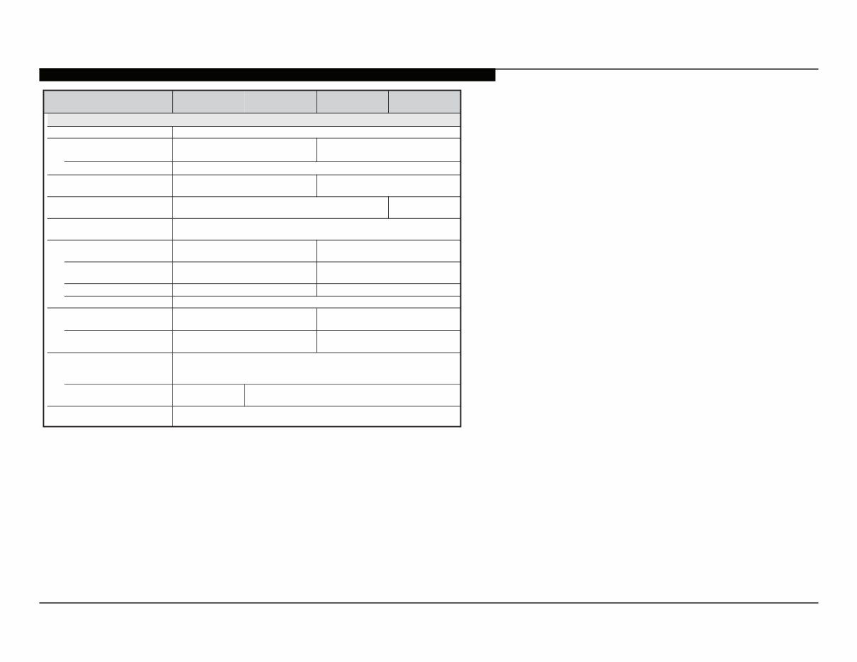
•Optional accessories availability depends on its stock.
•Design and specifications are subject to change without notice.
Model name KDL- 40EX400
40EX401
32EX400 32EX301
Power requirement 110-240 V AC, 50/60 Hz (U.S.A./Canada 120 V AC, 60 Hz)
Power consumption
135 W
in use
in standby Less than 0.23 W with 120 V AC and with 240 V AC less than 0.4 W
Screen size
(inches measured diagonally)
40
31.5
(32 class)
Display resolution 1,920 dots (horizontal) × 1,080 lines (vertical) 1,366 dots (horiz)
× 768 lines (vert)
Speaker/Full range (2) (mm)
(inches)
45 × 130
(1
13
/16 × 5
1
/8)
Dimensions with stand (mm)
(inches)
992 × 635 × 250
39
1
/8 × 25 × 9
7
/8
800 × 532 × 220
31
1
/2 × 21 × 8
3
/4
without stand (mm)
(inches)
992 × 598 × 100
39
1
/8 × 23
5
/8 × 4
800 × 497 × 97
31
1
/2 × 19
5
/8 × 3
7
/8
wall-mount hole pattern (mm) 0 0 3 × 0 0 3
) m m ( e z i s w e r c s t n u o m - l l a w
Mass with stand (kg)
(lb.)
15.9
35.1
11.0
24.3
without stand (kg)
(lb.)
13.9
30.7
9.5
21.0
(1)/Quick Setup Guide (1)/Warranty Card (1)/Safety and Regulatory Booklet
(1)/Software License (1)/Stand installation guide (1)/Table-Top Stand (1 set)
common to all models
) 7 ( w e r c S ) 4 ( w e r c S s l e d o m l a u d i v i d n i
Optional accessories Connecting cables / Support Belt Kit / Wall-Mount Bracket: SU-WL500
Supplied accessories Remote control RM-YD035 (1)/Size AAA batteries (2)/Operating Instructions
170 W
0 0 2 × 0 0 2
M6
KDL-32EX301/32EX400/40EX400/40EX401 3
CAUTION
These servicing instructions are for use by qualified service personnel only. To reduce the risk of electric shock, do not perform any servicing
other than that contained in the operating instructions unless you are qualified to do so.
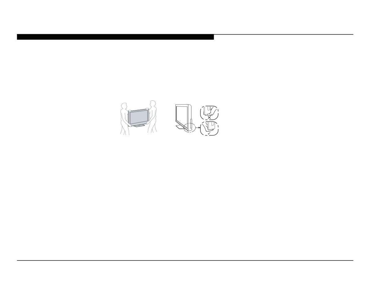
CARRYING THE TV
•Carry the TV with the adequate number of people; larger size TVs require two or more people.
•Correct hand placement while carrying the TV is very important for safety and to avoid
damage.
WARNING!!
An isolation transformer should be used during any service to avoid possible shock hazard, because of live chassis. The chassis of this
receiver is directly connected to the AC power line.
! SAFETY-RELATED COMPONENT WARNING!!
Components identified by shading and ! mark on the exploded views are critical for safe operation.
Replace all components with Sony parts whose part numbers appear as shown in this manual or in supplements published by Sony. It is
essential that all critical parts be replaced only with the part number specified in this manual to prevent electric shock, fire, or other hazard.
Circuit adjustments that are critical for safe operation are identified in this manual.
Follow these procedures whenever critical components are replaced or improper operation is suspected.
NOTE: Do not modify the original design without obtaining written permission from the manufacturer or you will void the original parts and
labor guarantee.
WARNINGS AND CAUTIONS
KDL-32EX301/32EX400/40EX400/40EX401 4
ATTENTION!!
Ces instructions de service sont à l’usage du personnel de service qualifié seulement. Pour prévenir le risque de choc électrique, ne pas faire
l’entretien autre que celui contenu dans le Mode d’emploi à moins que vous soyez qualifié faire ainsi.
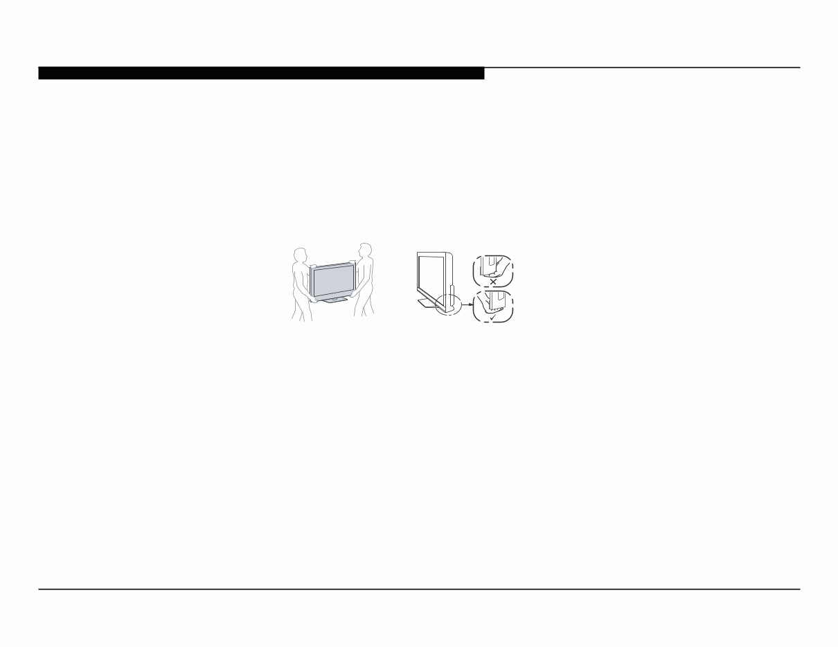
POUR TRANSPORTER LE TÉLÉVISEUR
•Transportez le téléviseur avec le nombre de personnes approprié ; un téléviseur de grande
taille doit être transporté par au moins deux personnes.
•Lors du transport du téléviseur, l’emplacement des mains est très important pour votre
sécurité, ainsi que pour éviter de causer des dommages.
ALERTE!!
Afin d’eviter tout risque d’electrocution provenant d’un chássis sous tension, un transformateur d’isolement doit etre utilisé lors de tout
dépannage. Le chássis de ce récepteur est directement raccordé à l’alimentation du secteur.
! ATTENTION AUX COMPOSANTS RELATIFS A LA SECURITE!!
Les composants identifies par une trame et par une marque ! sur les schemas de principe, les vues explosees et les listes de pieces sont
d’une importance critique pour la securite du fonctionnement. Ne les remplacer que par des composants Sony dont le numero de piece est
indique dans le present manuel ou dans des supplements publies par Sony. Les reglages de circuit dont l’importance est critique pour la
securite du fonctionnement sont identifies dans le present manuel. Suivre ces procedures lors de chaque remplacement de composants
critiques, ou lorsqu’un mauvais fonctionnement suspecte.
WARNING AND CAUTIONS
KDL-32EX301/32EX400/40EX400/40EX401 5
SAFETY-RELATED WARNING
USE CAUTION WHEN HANDLING THE LCD PANEL
When repairing the LCD panel, be sure you are grounded by using a wrist band.
When installing the LCD panel on a wall, the LCD panel must be secured using the 4 mounting holes on the rear cover.
1) Do not press on the panel or frame edge to avoid the risk of electric shock.
2) Do not scratch or press on the panel with any sharp objects.
3) Do not leave the module in high temperatures or in areas of high humidity for an extended period of time.
4) Do not expose the LCD panel to direct sunlight.
5) Avoid contact with water. It may cause a short circuit within the module.
6) Disconnect the AC power when replacing the inverter circuit.
(High voltage occurs at the inverter circuit at 650Vrms.)
7) Always clean the LCD panel with a soft cloth material.
8) Use care when handling the wires or connectors of the inverter circuit. Damaging the wires may cause a short.
9) Protect the panel from ESD to avoid damaging the electronic circuit (C-MOS).
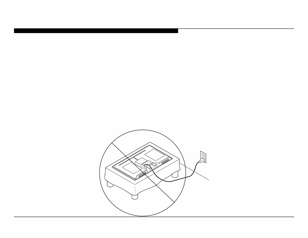
10) During the repair, DO NOT leave the Power On for more than 1 hour while the TV is face down on a cloth.
KDL-32EX301/32EX400/40EX400/40EX401 6
After correcting the original service problem, perform the following safety checks before releasing the set to the customer:
SAFETY CHECK-OUT
1. Check the area of your repair for unsoldered or poorly soldered connections.
Check the entire board surface for solder splashes and bridges.
2. Check the interboard wiring to ensure that no wires are “pinched” or touching
high-wattage resistors.
3. Check that all control knobs, shields, covers, ground straps, and mounting
hardware have been replaced. Be absolutely certain that you have replaced
all the insulators.
4. Look for unauthorized replacement parts, particularly transistors, that were
installed during a previous repair. Point them out to the customer and
recommend their replacement.
5. Look for parts which, though functioning, show obvious signs of deterioration.
Point them out to the customer and recommend their replacement.
6. Check the line cords for cracks and abrasion. Recommend the replacement
of any such line cord to the customer.
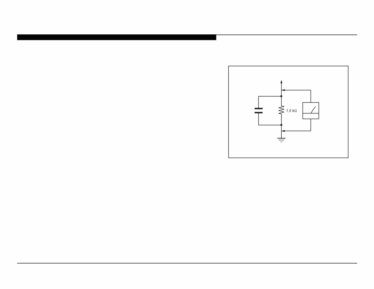
7. Check the antenna terminals, metal trim, “metallized” knobs, screws, and
all other exposed metal parts for AC leakage. Check leakage as described
below.
To Exposed Metal
Parts on Set
0.15 μF
Earth Ground
AC
Voltmeter
(0.75V)
Figure A. Using an AC voltmeter to check AC leakage.
You're Reading a Preview
What's Included?
Fast Download Speeds
Online & Offline Access
Access PDF Contents & Bookmarks
Full Search Facility
Print one or all pages of your manual
$31.99
Viewed 80 Times Today


Secure transaction
What's Included?
Fast Download Speeds
Online & Offline Access
Access PDF Contents & Bookmarks
Full Search Facility
Print one or all pages of your manual
$31.99
These digital manuals cover the following models:
- KDL-32EX301
- KDL-32EX400
- KDL-40EX400
- KDL-40EX401
The manuals include information on self-diagnosis functions, disassembly/part number details, service adjustments, circuit board locations, and block diagrams.
Manual Details:
- Format: .PDF
- Pages: 25
- Language: English
- Compatibility: Windows/Mac
- Printable Pages: Yes


