

Sharp LC-19SK24U LC-19SB14U LCD TV Service Manual
What's Included?
Fast Download Speeds
Online & Offline Access
Access PDF Contents & Bookmarks
Full Search Facility
Print one or all pages of your manual
In the interests of user-safety (Required by safety regulations in some countries) the set should be re-
stored to its original condition and only parts identical to those specified should be used.
MODEL
This document has been published to be used for
after sales service only.
The contents are subject to change without notice.
LCD COLOR TELEVISION
CONTENTS
ネ IMPORTANT SERVICE SAFETY PRECAUTION .......................................................................................... 2
ネ SPECIFICATIONS ......................................................................................................................................... 5
ネ OPERATION MANUAL .................................................................................................................................. 7
ネ DIMENSIONS .............................................................................................................................................. 11
ネ REMOVING OF MAJOR PARTS ................................................................................................................. 13
ネ ADJUSTING PROCEDURE OF EACH SECTION ...................................................................................... 18
ネ PUBLIC MODE SETTING PROCEDURE ................................................................................................... 43
ネ TROUBLESHOOTING TABLE ..................................................................................................................... 48
ネ MAJOR IC INFORMATIONS ....................................................................................................................... 56
ネ BLOCK DIAGRAM....................................................................................................................................... 58
ネ OVERALL WIRING DIAGRAM .................................................................................................................... 60
ネ DESCRIPTION OF SCHEMATIC DIAGRAM .............................................................................................. 62
ネ SCHEMATIC DIAGRAM
RC/LED Unit .............................................................................................................................................. 63
MAIN Unit .................................................................................................................................................. 64
SUB Unit .................................................................................................................................................... 82
POWER_INVERTER Unit .......................................................................................................................... 86
KEY Unit .................................................................................................................................................... 88
ネ PRINTED WIRING BOARD ASSEMBLIES ................................................................................................. 89
ネ REPLACEMENT PARTS LIST................................................................................................................... 109
ネ PACKING OF THE SET ............................................................................................................................. 126
Page
N87B1LC19K24U
LC-19SK24U
LC-19SK24U-W
LC-19SB24U
LC-19SB24U-W
LC-19SB14U
LC-19D44U
LC-19SK4U/U-W
LC-19SB4U/U-W
LC-19SB14U
LC-19D44U
A V
CAUTION: FOR CONTINUED
PROTECTION AGAINST A RISK OF
FIRE REPLACE ONLY WITH SAME
TYPE F7501 (5A, 250V) AND F7502
(2.5A, 250V) FUSE.
SAFETY NOTICE
Many electrical and mechanical parts in LCD television
have special safety-related characteristics.
These characteristics are often not evident from
visual inspection, nor can protection afforded by
them be necessarily increased by using replacement
components rated for higher voltage, wattage, etc.
Replacement parts which have these special safety
characteristics are identified in this manual; electrical
components having such features are identified by "!"
IMPORTANT SERVICE SAFETY PRECAUTION
Service work should be performed only by qualified service technicians who are thor-
oughly familiar with all safety checks and the servicing guidelines which follow:
and shaded areas in the Replacement Parts Lists and
Schematic Diagrams.
For continued protection, replacement parts must be
identical to those used in the original circuit.
The use of substitute replacement parts which do not
have the same safety characteristics as the factory
recommended replacement parts shown in this service
manual, may create shock, fire or other hazards.
WARNING
1. For continued safety, no modification of any circuit
should be attempted.
2. Disconnect AC power before servicing.
BEFORE RETURNING THE RECEIVER
(Fire & Shock Hazard)
Before returning the receiver to the user, perform
the following safety checks:
1. Inspect all lead dress to make certain that leads are
not pinched, and check that hardware is not lodged
between the chassis and other metal parts in the
receiver.
2. Inspect all protective devices such as non-metallic
control knobs, insulation materials, cabinet backs,
adjustment and compartment covers or shields,
isolation resistor-capacitor networks, mechanical
insulators, etc.
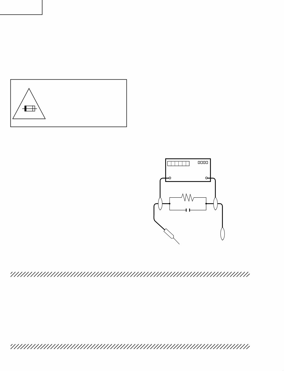
3. To be sure that no shock hazard exists, check for
leakage current in the following manner.
• Plug the AC cord directly into a 120 volt AC outlet,
and connect the DC power cable into the receiver's
DC jack. (Do not use an isolation transformer for this
test).
• Using two clip leads, connect a 1.5k ohm, 10 watt
resistor paralleled by a 0.15µF capacitor in series
with all exposed metal cabinet parts and a known
earth ground, such as electrical conduit or electrical
ground connected to an earth ground.
• Use an AC voltmeter having with 5000 ohm per volt,
or higher, sensitivity or measure the AC voltage drop
across the resistor.
• Connect the resistor connection to all exposed metal
parts having a return to the chassis (antenna, metal
cabinet, screw heads, knobs and control shafts,
escutcheon, etc.) and measure the AC voltage drop
across the resistor.
All checks must be repeated with the AC cord plug
connection reversed. (If necessary, a nonpolarized
adaptor plug must be used only for the purpose of
completing these checks.)
Any reading of 0.75V peak (this corresponds to 0.5
mA. peak AC.) or more is excessive and indicates
a potential shock hazard which must be corrected
before returning the monitor to the owner.
DVM
AC SCALE
1.5k ohm
10W
TO EXPOSED
METAL PARTS
CONNECT TO
KNOWN EARTH
GROUND
0.15 µF
TEST PROBE
LC-19SK4U/U-W
LC-19SB4U/U-W
LC-19SB14U
LC-19D44U
PRECAUTION: POUR LA
PROTECTION CONTINUE
CONTRE LES RISQUES
D'INCENDIE, REMPLACER LE
FUSIBLE PAR UN FUSIBLE DE
MEME TYPE F7501 (5A, 250V) et
F7502 (2.5A, 250V).
AVIS POUR LA SECURITE
De nombreuses pièces, électriques et mécaniques,
dans les téléviseurs de l' afficharge à cristaux liquides
présentent des caractéristiques spéciales relatives à la
sécurité.
Ces caracténstiques ne sont souvent pas évidentes
à vue. Le degré de protection ne peut pas être
nécessairement augmentée en utilisant des pièces de
remplacement étalonnées pour haute tension, puissance,
etc.
Les pièces de remplacement qui présentent ces
caractéristiques sont identifiées dans ce manuel; les
pièces électriques qui présentent ces particularités sont
identifiées par la marque "!" et hachurées dans la
liste des pièces de remplacement et les diagrammes
schématiques.
Pour assurer la protection, ces pièces doivent être
identiques à celles utilisées dans le circuit d'origine.
L'utilisation de pièces qui n'ont pas les mêmes
caractéristiques que les pièces recommandées par
l'usine, indiquées dans ce manuel, peut provoquer des
électrocutions, incendies ou autres accidents.
PRECAUTIONS A PRENDRE LORS DE LA REPARATION
La réparation ne peut être effectuée que par un technicien spécialisé qui s'est
parfaitement accoutumé à toute vérification de sécurité et aux conseils suivants.
AVERTISSEMENT
1. Pour la sécurité continue, n'entreprendre aucune
modification de tout circuit.
2. Débrancher l'alimentation CA avant la réparation.
AVANT DE RENDRE LE RECEPTEUR A L’UTI-
LISATEUR (Incendie et choc électrique)
Avant de rendre le récepteur à l'utilisateur, effectuer
les vérifications suivantes.
1. Inspecter tous les faisceaux de câbles pour s'assurer
que les fils ne soient pas pincés ou qu'un outil ne
soit pas placé entre le châssis et les autres pièces
métalliques du récepteur.
2. Inspecter tous les dispositifs de protection comme
les boutons de commande non-métalliques,
les isolants, le dos du coffret, les couvercles ou
blindages de réglage et de compartiment, les
réseaux de résistance-capacité, les isolateurs
mécaniques, etc.
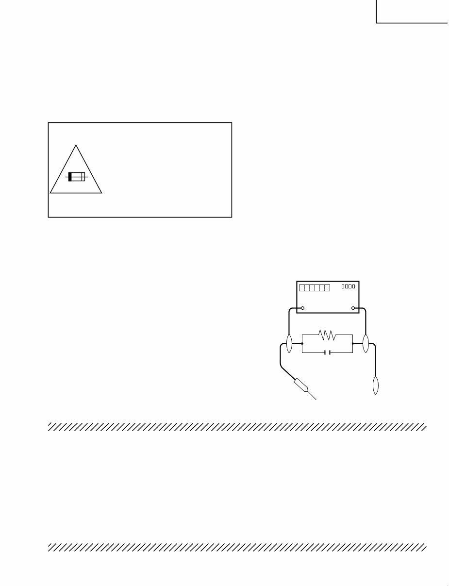
3. S'assurer qu'il n'y ait pas de danger d'électrocution
en vérifiant la fuite de courant, de la facon suivante:
• Brancher le cordon d'alimentation directem-ent à
une prise de courant de 120V. (Ne pas utiliser de
transformateur d'isolation pour cet essai).
• A l'aide de deux fils à pinces, brancher une
résistance de 1.5kΩ 10 watts en parallèle avec un
condensateur de 0.15µF en série avec toutes les
pièces métalliques exposées du coffret et une terre
connue comme une conduite électrique ou une prise
de terre branchée à la terre.
• Utiliser un voltmètre CA d'une sensibilité d'au moins
5000Ω/V pour mesurer la chute de tension CA en
travers de la résistance.
• Toucher avec la sonde d'essai les pièces métalliques
exposées qui présentent une voie de retour au
châssis (antenne, coffret métallique, tête des vis,
arbres de commande et des boutons, écusson,
etc.) et mesurer la chute de tension CA en travers
de la résistance. Toutes les vérifications doivent
être refaites après avoir inversé la fiche du cordon
d'alimentation. (Si nécessaire, une prise d'adpatation
non polarisée doit être utilisée dans le but de
terminer ces vérifications.)
La tension de pointe mesurèe ne doit pas dépasser
0.75V (correspondante au courant CA de pointe de
0.5mA). Dans le cas contraire, il y a une possibilité
de choc électrique qui doit être supprimée avant de
rendre le récepteur au client.
A V
DVM
AC SCALE
1.5k ohm
10W
TO EXPOSED
METAL PARTS
CONNECT TO
KNOWN EARTH
GROUND
0.15 µF
TEST PROBE
4
LC-19SK24U/U-W
LC-19SB24U/U-W
LC-19SB14U
LC-19D44U
Precautions for using lead-free solder
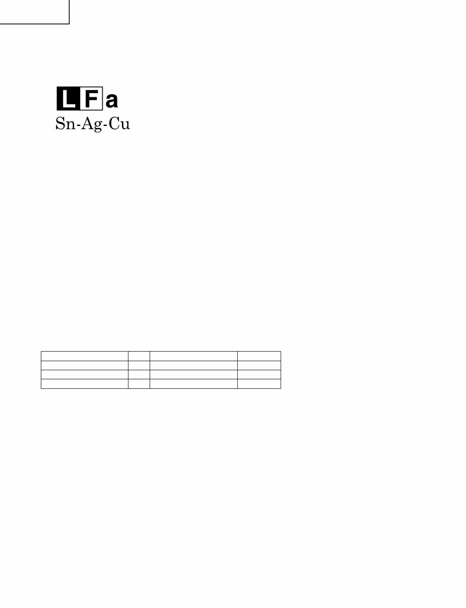
1 Employing lead-free solder
"All PWBs" of this model employs lead-free solder. The LF symbol indicates lead-free solder, and is attached on
the PWBs and service manuals. The alphabetical character following LF shows the type of lead-free solder.
Example:
2 Using lead-free wire solder
When fixing the PWB soldered with the lead-free solder, apply lead-free wire solder. Repairing with conventional
lead wire solder may cause damage or accident due to cracks.
As the melting point of lead-free solder (Sn-Ag-Cu) is higher than the lead wire solder by 40°C, we recommend
you to use a dedicated soldering bit, if you are not familiar with how to obtain lead-free wire solder or soldering
bit, contact our service station or service branch in your area.
Soldering
As the melting point of lead-free solder (Sn-Ag-Cu) is about 220°C which is higher than the conventional lead
solder by 40°C, and as it has poor solder wettability, you may be apt to keep the soldering bit in contact with the
PWB for extended period of time. However, Since the land may be peeled off or the maximum heat-resistance
temperature of parts may be exceeded, remove the bit from the PWB as soon as you confirm the steady
soldering condition.
Lead-free solder contains more tin, and the end of the soldering bit may be easily corroded. Make sure to turn
on and off the power of the bit as required.
If a different type of solder stays on the tip of the soldering bit, it is alloyed with lead-free solder. Clean the bit
after every use of it.
When the tip of the soldering bit is blackened during use, file it with steel wool or fine sandpaper.
Be careful when replacing parts with polarity indication on the PWB silk.
Indicates lead-free solder of tin, silver and copper.
Lead-free wire solder for servicing
Part No, ★ Description Code
ZHNDAi123250E J φ0.3mm 250g(1roll) BL
ZHNDAi126500E J φ0.6mm 500g(1roll) BK
ZHNDAi12801KE J φ1.0mm 1kg(1roll) BM
LC-19SK24U/U-W
LC-19SB24U/U-W
LC-19SB14U
LC-19D44U
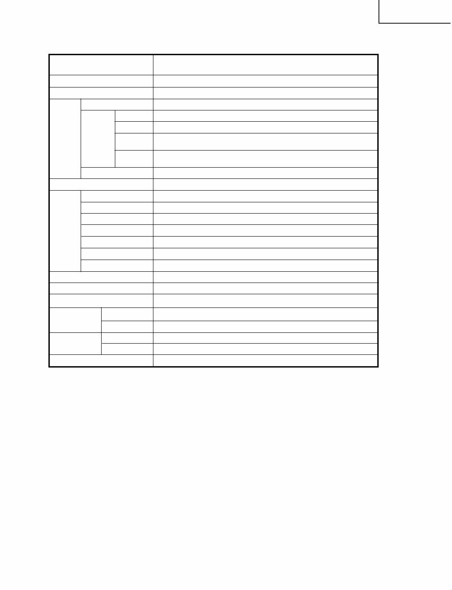
SPECIFICATIONS
*1
Emergency alert messages via Cable are unreceivable.
*2
The dimensional drawings are shown on the inside back cover.
• As part of policy of continuous improvement, SHARP reserves the right to make design and specification changes for product
improvement without prior notice. The performance specification figures indicated are nominal values of production units.
There may be some deviations from these values in individual units.
LCD panel
Item Model: LC-19SK24U/LC-19SK24U-W/LC-19SB24U/LC-19SB24U-W/LC-19SB14U
18.5o Active Matrix type a-Si TN LCD ( Screen size 18
1
/
2
o measured diagonally)
2W g 2
Number of dots
TV
Function
TV-standard (CCIR)
Receiving
Channel
VHF/UHF
CATV(analog)
Digital Terrestrial
Broadcast (8VSB)
Audio multiplex
Audio out
Terminals INPUT 1
INPUT 2
INPUT 3
INPUT 4
ANTENNA
DIGITAL AUDIO OUTPUT
OSD language
Power Requirement
Power Consumption
Weight
Dimension
*2
(W g H g D)
Operating temperature
3,147,264 dots (1366 g 768 g 3 dots)
American TV Standard ATSC/NTSC System
VHF 2-13ch, UHF 14-69ch
1-125ch (STD, HRC, IRC)
2-69ch
BTSC System
COMPONENT in
AV in, S-VIDEO in
HDMI in with HDCP(480P, 720P/60Hz, 1080I/60Hz, VGA), HDMI Analog Audio in
15 pin mini D-sub female connector, PC Audio in (Ø 3.5 mm jack)
75 q Unbalance, F Type g 1 for Analog (VHF/UHF/CATV) and Digital (AIR/CABLE)
Optical Digital audio output g 1 (Dolby Digital)
English/French/Spanish
AC 120 V, 60 Hz
e32°F to e104°F (0°C to e40°C)
TV only
TV + stand
TV + stand
TV only
45 W (0.5 W Standby with AC 120V)
11.4 lbs./5.2 kg
10.3 lbs./4.7 kg
18
3
/
16
g 12
19
/
32
g 2
61
/
64
inch
18
3
/
16
g 14
11
/
64
g 7
63
/
64
inch
Digital Cable
*1
(64/256 QAM)
1-135ch
Headphone Ø 3.5 mm jack (Audio Output)
LC-19SK24U/U-W
LC-19SB24U/U-W
LC-19SB14U
LC-19D44U
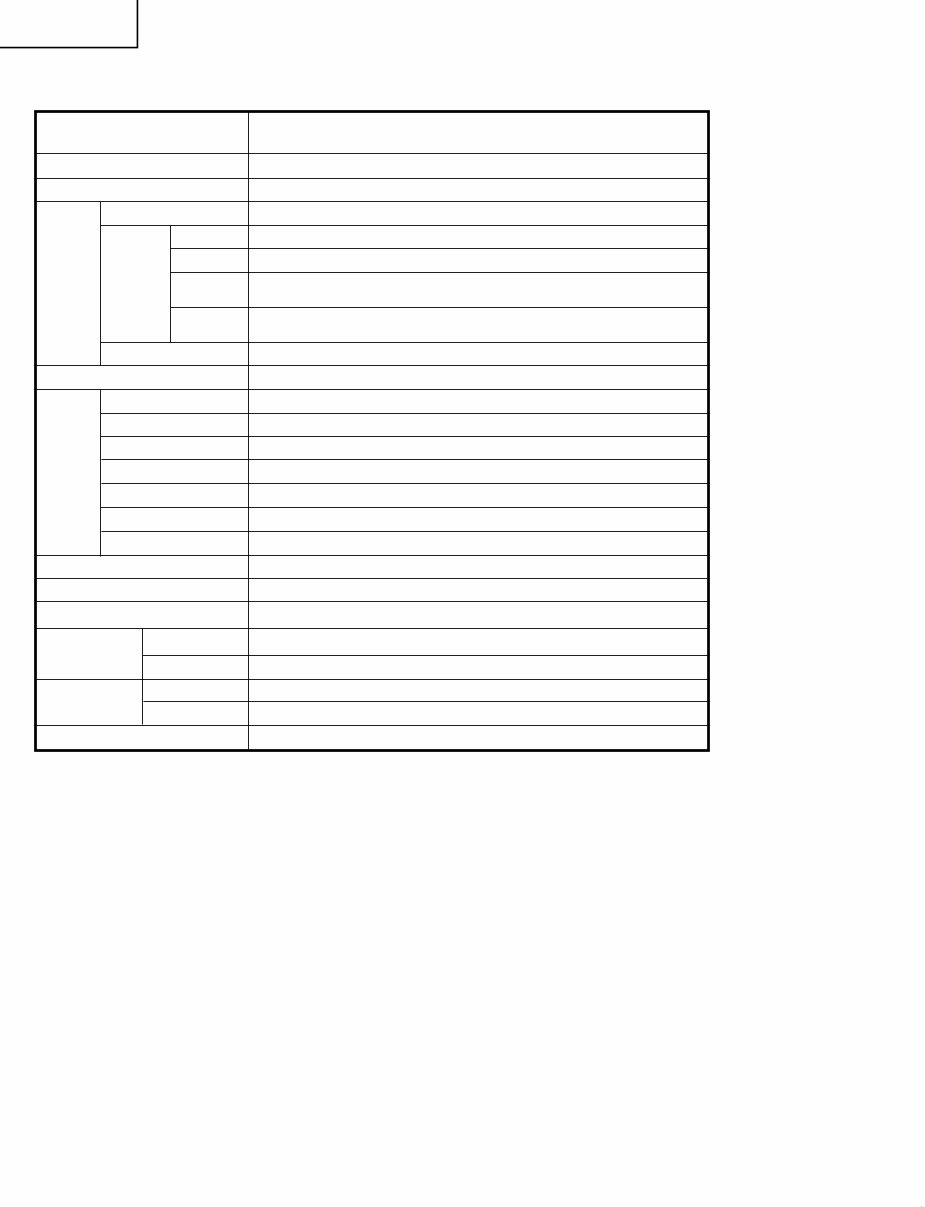
SPECIFICATIONS(Continued)
*1
Emergency alert messages via Cable are unreceivable.
*2
The dimensional drawings are shown on the inside back cover.
• As part of policy of continuous improvement, SHARP reserves the right to make design and specification changes for product
improvement without prior notice. The performance specification figures indicated are nominal values of production units.
There may be some deviations from these values in individual units.
LCD panel
Item Model: LC-19D44U
18.5o Active Matrix type a-Si TN LCD ( Screen size 18
1
/
2
o measured diagonally)
2W g 2
Number of dots
TV
Function
TV-standard (CCIR)
Receiving
Channel
VHF/UHF
CATV(analog)
Digital Terrestrial
Broadcast (8VSB)
Audio multiplex
Audio out
Terminals INPUT 1
INPUT 2
INPUT 3
INPUT 4
ANTENNA
DIGITAL AUDIO OUTPUT
OSD language
Power Requirement
Power Consumption
Weight
Dimension
*2
(W g H g D)
Operating temperature
3,147,264 dots (1366 g 768 g 3 dots)
American TV Standard ATSC/NTSC System
VHF 2-13ch, UHF 14-69ch
1-125ch (STD, HRC, IRC)
2-69ch
BTSC System
COMPONENT in
AV in, S-VIDEO in
HDMI in with HDCP(480P, 720P/60Hz, 1080I/60Hz, VGA), HDMI Analog Audio in
15 pin mini D-sub female connector, PC Audio in (Ø 3.5 mm jack)
75 q Unbalance, F Type g 1 for Analog (VHF/UHF/CATV) and Digital (AIR/CABLE)
Optical Digital audio output g 1 (Dolby Digital)
English/French/Spanish
AC 120 V, 60 Hz
e32°F to e104°F (0°C to e40°C)
TV only
TV + stand
TV + stand
TV only
45 W (0.5 W Standby with AC 120V)
11.9 lbs./5.4 kg
10.1 lbs./4.5 kg
18
3
/
16
g 12
19
/
32
g 3
1
/
32
inch
18
3
/
16
g 14
11
/
64
g 7
63
/
64
inch
Digital Cable
*1
(64/256 QAM)
1-135ch
Headphone Ø 3.5 mm jack (Audio Output)
LC-19SK24U/U-W
LC-19SB24U/U-W
LC-19SB14U
LC-19D44U
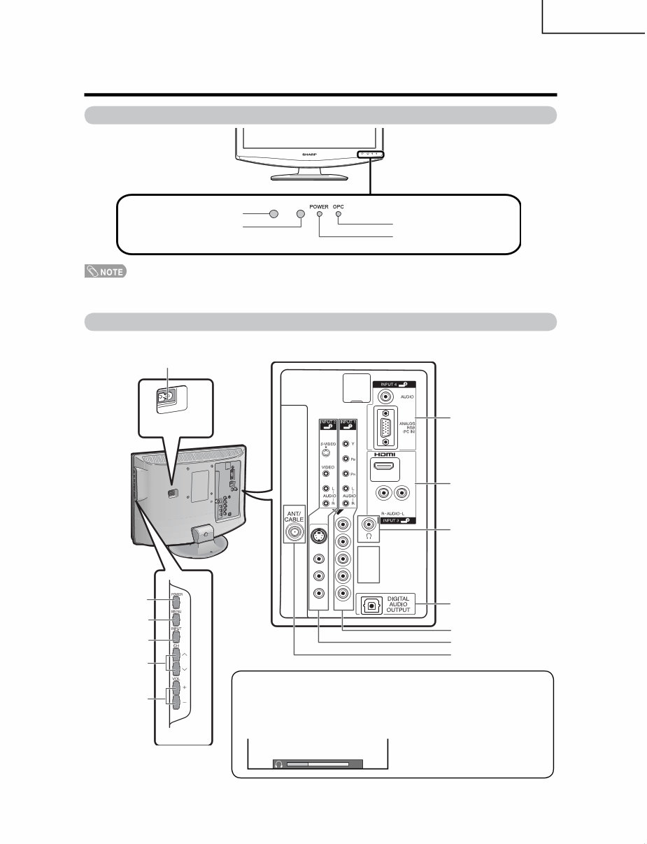
OPERATION MANUAL
Part names
POWER
button
TV (Front)
Channel
buttons
(CHr/s)
Volume
buttons
( VOLk/ l)
INPUT
button
POWER indicator
OPC sensor*
Remote control sensor
*OPC: Optical Picture Control
OPC indicator
TV (Side/Rear)
INPUT 4 terminals
(PC IN)
INPUT 1 terminals
DIGITAL AUDIO OUTPUT
terminal
Antenna/Cable in
AC INPUT
terminal
INPUT 2 terminals
MENU
button
INPUT 3 terminals
(HDMI)
HEADPHONE terminal
Regarding the headphone jack
• Use headphones with a stereo mini plug (Ø 3.5 mm).
• Be sure to unplug headphones from the jack when they are not in use.
• The speakers do not output volume when headphones are plugged in.
• You can set the volume to different levels for each input source.
Volume display when
headphones are plugged in
20
LC-19SK24U/U-W
LC-19SB24U/U-W
LC-19SB14U
LC-19D44U
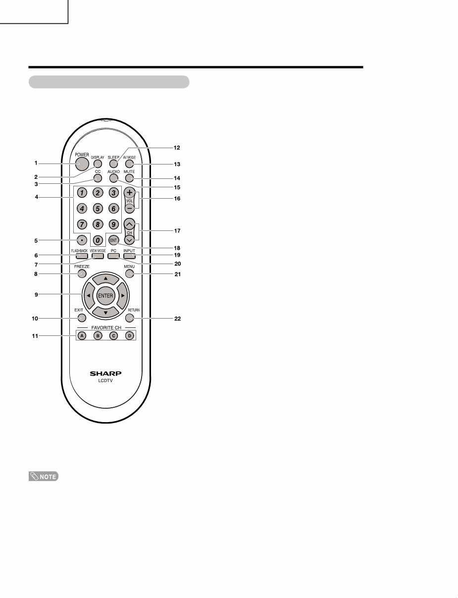
1 POWER: Switch the TV power on or enters standby.
2 DISPLAY: Display the channel information.
3 CC: Display captions from a closed-caption source.
4 0 – 9: Set the channel.
5 • (DOT)
6 FLASHBACK: Return to the previous channel or
external input mode.
7 VIEW MODE: Select the screen size.
8 FREEZE: Set the still image. Press again to return to
normal screen.
9 a/b/c/d/ENTER: Select a desired item on the
screen.
10 EXIT: Turn off the menu screen.
11 FAVORITE CH
A, B, C, D: Select 4 preset favorite channels in 4
different categories.
While watching, you can toggle the selected channels
by pressing A, B, C and D.
12 SLEEP: Set the sleep timer.
13 AV MODE: Select an audio or video setting. (When
the input source is TV, INPUT 1 or 2: STANDARD,
MOVIE, GAME, USER, DYNAMIC (Fixed), DYNAMIC.
When the input source is INPUT 3: STANDARD,
MOVIE, GAME, PC, USER, DYNAMIC (Fixed),
DYNAMIC. When the input source is INPUT 4:
STANDARD, PC, USER)
14 MUTE: Mute the sound.
15 AUDIO: Selects the MTS/SAP or the audio mode
during multi-channel audio broadcasts.
16 VOL k/l: Set the volume.
17 CHr/s: Select the channel.
18 ENT: Jumps to a channel after selecting with the 0–9
buttons.
19 INPUT: Select a TV input source. (TV, INPUT 1,
INPUT 2, INPUT 3, INPUT 4)
20 PC: Quickly access to PC mode.
21 MENU: Display the menu screen.
22 RETURN: Return to the previous menu screen.
Remote control unit
• When using the remote control unit, point it at the TV.
Part names
9
LC-19SK24U/U-W
LC-19SB24U/U-W
LC-19SB14U
LC-19D44U
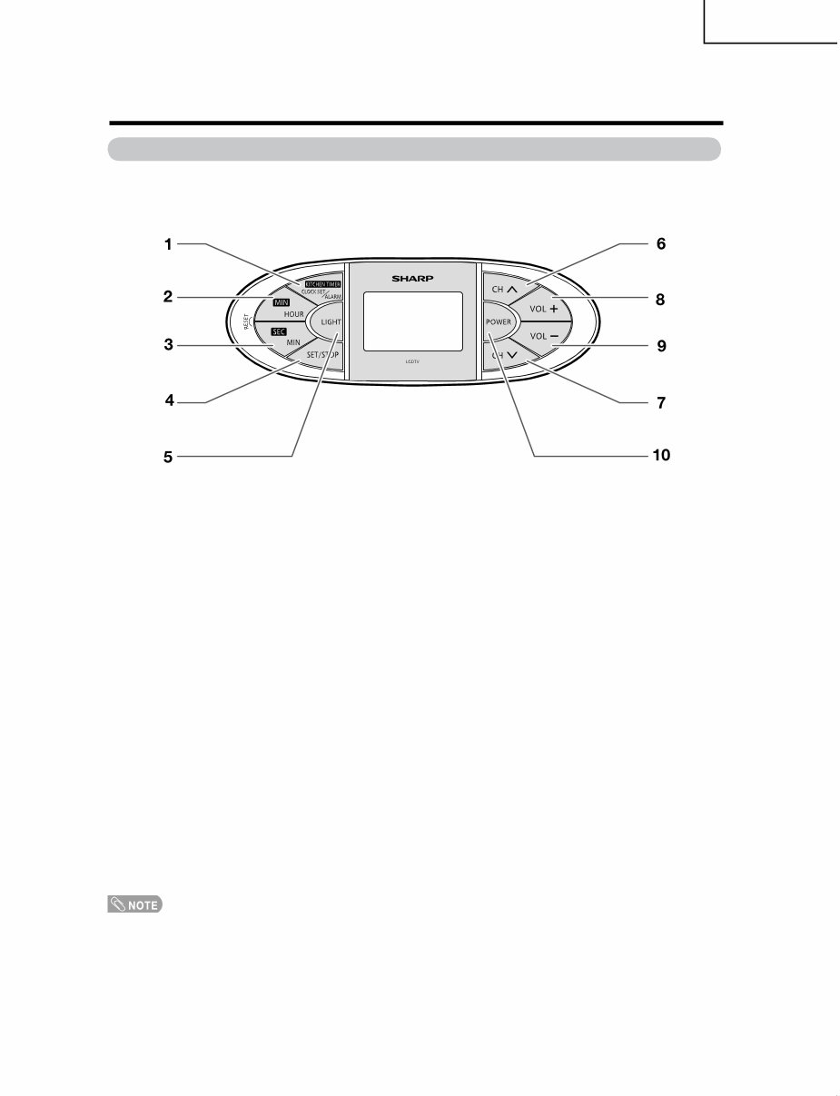
Kitchen Remote control unit (LC-19SK24U/LC-19SK24U-W/LC-19D44U)
1 KITCHEN TIMER/CLOCK SET/ALARM:
Set the kitchen timer, clock or alarm.
2 MIN/HOUR :
Set the minute of kitchen timer and the hour of clolck or alarm.
3 SEC/MIN :
Set the second of kitchen timer and the minute of clock or alarm.
4 SET/STOP :
Confirm setting or stop beeper sound.
5 LIGHT :
Light on the remote control LCD backlight.
6,7 CHr/CHs :
Select the channel.
8 VOL+ :
To increase the volume.
9 VOL- :
To decrease the volume.
10 POWER :
Switch the TV power on or enters standby.
• The method of using the Kitchcen Remote control unit, please see page 50~52 of operation manual.
Part names
10
LC-19SK24U/U-W
LC-19SB24U/U-W
LC-19SB14U
LC-19D44U
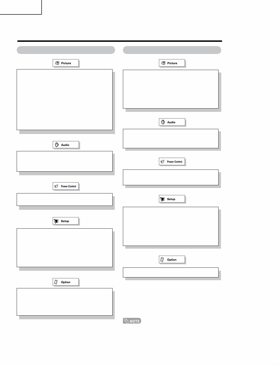
Menu items for TV/INPUT 1/2 Menu items for HDMI/PC-IN
Treble
Bass
Balance
Reset
• Some menu items may not be displayed depending on the
selected input source.
OPC
Backlight
Contrast
Brightness
Color
Tint
Sharpness
Advanced
C.M.S
Color Temp.
Film Mode
3D-Y/C
Monochrome
I/P Setting
Reset
Treble
Bass
Balance
Reset
OPC
Backlight
Contrast
Brightness
Advanced
C.M.S
Color Temp.
Monochrome
Reset
No Signal Off
No Operation Off
No Signal Off
No Operation Off
Power Management
EZ Setup
CH Setup
Antenna Setup-DIGITAL
Input Label
Parental CTRL
Position
Rotate
Language
Reset
Input Label
Parental CTRL
Position
PC Setup
HDMI Audio Select
HDMI Auto View
Rotate
Language
Reset
Audio Only
DNR
Audio Only
Digital Audio
Color System
Digital Caption Setup
Favorite CH
Basic adjustment settings
You're Reading a Preview
What's Included?
Fast Download Speeds
Online & Offline Access
Access PDF Contents & Bookmarks
Full Search Facility
Print one or all pages of your manual
$31.99
Viewed 11 Times Today


Secure transaction
What's Included?
Fast Download Speeds
Online & Offline Access
Access PDF Contents & Bookmarks
Full Search Facility
Print one or all pages of your manual
$31.99
This LCD TV Service Manual is an essential resource for both professional mechanics and DIY enthusiasts. It covers a range of models including LC-19SK24U, LC-19SB14U, LC-19SB24U, LC-19SB24U-W, and LC-19D44U. The manual includes important service safety precautions, detailed specifications, operation manual, dimensions, and procedures for removing major parts and adjusting each section. It also provides troubleshooting tables, information on major ICs, block diagrams, overall wiring diagrams, and detailed schematic diagrams for RC/LED Unit, Main Unit, Sub Unit, Power Inverter Unit, and Key Unit. Additionally, it includes information on printed wiring board assemblies, a replacement parts list, and packing of the set.
- Language: English
- Pages: 128
- Format: PDF
- Platform: Windows and MAC


