Technical Specifications, Connections, and Chassis Overview EN 2 LC8.1U LA 1. 1. Technical Specifications, Connections, and Chassis Overview Index of this chapter: 1.1 Technical Specifications 1.2 Connection Overview 1.3 Chassis Overview Notes: • Figures can deviate due to the different set executions. • Specifications are indicative (subject to change). 1.1 Technical Specifications 1.1.1 Vision Display type : LCD Screen size : 32" (82 cm), 16:9 : 42" (107 cm), 16:9 : 47" (120 cm), 16:9 : 52" (132 cm), 16:9 Resolution (H × V pixels) : 1366×768 (32") : 1366×768(42PFL34x) : 1920×1080 (rest) Dyn. contrast ratio : 26000:1 (32" and 42PFL34x) : 29000:1 (rest 42" & 47") : 33000:1 (52") Min. light output (cd/m 2 ) : 500 Typ. response time (ms) : 2 ~ 8 (depending on model number) Viewing angle (H × V degrees) : 178 × 178 (rest) : 160 × 160 (52") Tuning system : PLL Presets/channels : 100 presets Tuner bands : VHF, UHF, S, H TV Color systems : ATSC : NTSC Video playback : NTSC Cable : Unscrambled digital cable - QAM Supported computer formats (60Hz) : 640 × 480 : 800 × 600 : 1024 × 768 : 1280 × 1024 : 1280 × 768 : 1360 × 768 : 1920 × 1080i : 1920 × 1080p (only for full HD sets) Supported video formats (60Hz) : 480i : 480p : 720p : 1080i : 1080p (only for full HD sets) 1.1.2 Sound Sound systems : Stereo : BBE ® : Dolby Digital ® Maximum power (W RMS ) : 20 ~ 30 (depending on model number) 1.1.3 Miscellaneous Power supply: - Mains voltage (V AC ) : 90 - 240 - Mains frequency (Hz) : 50 / 60 Ambient conditions: - Temperature range (°C) : +5 to +40 - Maximum humidity : 90% R.H. Power consumption (values are indicative) - Normal operation (W) : ≈ 240 - Stand-by (W) : < 1 Dimensions (W × H × D inch) - 32" : 32.3 × 20.4 × 3.6 - 42" : 40.7 × 26.2 × 3.5 - 47" : 44.8 × 28.5 × 4.0 - 52" : 51.2 × 31.4 × 4.7 Weight without stand (lb.) - 32" : 31.9 - 42" : 45.1 - 47" : 60.5 - 52" : 83.8
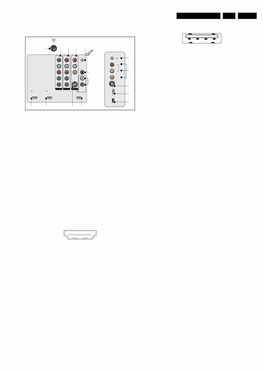
Technical Specifications, Connections, and Chassis Overview EN 3 LC8.1U LA 1. 1.2 Connection Overview Figure 1-1 Side and rear I/O connections Note: The following connector color abbreviations are used (acc. to DIN/IEC 757): Bk= Black, Bu= Blue, Gn= Green, Gy= Grey, Rd= Red, Wh= White, and Ye= Yellow. 1.2.1 Side Connections Head phone - Out (12) Bk - Head phone 32 - 600 ohm / 10 mW rt Cinch: Video CVBS - In, Audio - In (13) Ye - Video CVBS 1 V PP / 75 ohm jq Wh - Audio L 0.5 V RMS / 10 kohm jq Rd - Audio R 0.5 V RMS / 10 kohm jq S-Video (Hosiden): Video Y/C - In (14) 1 - Ground Y Gnd H 2 - Ground C Gnd H 3 - Video Y 1 V PP / 75 ohm j 4 - Video C 0.3 V PP / 75 ohm j HDMI4: Digital Video, Digital Audio - In (15) Figure 1-2 HDMI (type A) connector 1 - D2+ Data channel j 2 - Shield Gnd H 3 - D2- Data channel j 4 - D1+ Data channel j 5 - Shield Gnd H 6 - D1- Data channel j 7 - D0+ Data channel j 8 - Shield Gnd H 9 - D0- Data channel j 10 - CLK+ Data channel j 11 - Shield Gnd H 12 - CLK- Data channel j 13 - n.c. 14 - n.c. 15 - DDC_SCL DDC clock j 16 - DDC_SDA DDC data jk 17 - Ground Gnd H 18 - +5V j 19 - HPD Hot Plug Detect j 20 - Ground Gnd H USB2.0 (16) Figure 1-3 USB (type A) 1 - +5V k 2 - Data (-) jk 3 - Data (+) jk 4 - Ground Gnd H 1.2.2 Rear Connections HDMI1, 2 & 3: Digital Video, Digital Audio - In (9, 10, 11) 1 - D2+ Data channel j 2 - Shield Gnd H 3 - D2- Data channel j 4 - D1+ Data channel j 5 - Shield Gnd H 6 - D1- Data channel j 7 - D0+ Data channel j 8 - Shield Gnd H 9 - D0- Data channel j 10 - CLK+ Data channel j 11 - Shield Gnd H 12 - CLK- Data channel j 13 - n.c. 14 - n.c. 15 - DDC_SCL DDC clock j 16 - DDC_SDA DDC data jk 17 - Ground Gnd H 18 - +5V j 19 - HPD Hot Plug Detect j 20 - Ground Gnd H HDMI3: Cinch: DVI Audio - In (7) Rd - Audio - R 0.5 V RMS / 10 kohm jq Wh - Audio - L 0.5 V RMS / 10 kohm jq Aerial - In (1) - - F-type (US) Coax, 75 ohm D AV1 & 2: Cinch: Video YPbPr - In, Audio - In (2, 3) Gn - Video Y 1 V PP / 75 ohm jq Bu - Video Pb 0.7 V PP / 75 ohm jq Rd - Video Pr 0.7 V PP / 75 ohm jq Wh - Audio L 0.5 V RMS / 10 kohm jq Rd - Audio R 0.5 V RMS / 10 kohm jq AV3: Cinch: Video CVBS - In, Audio - In (4) Ye - Video CVBS 1 V PP / 75 ohm jq Wh - Audio L 0.5 V RMS / 10 kohm jq Rd - Audio R 0.5 V RMS / 10 kohm jq AV3: S-Video (Hosiden): Video Y/C - In (8) 1 - Ground Y Gnd H 2 - Ground C Gnd H 3 - Video Y 1 V PP / 75 ohm j 4 - Video C 0.3 V PP P / 75 ohm j Service Connector UART (5) 1 - UART_TX Transmit k 2 - Ground Gnd H 3 - UART_RX Receive j Cinch: S/PDIF - Out (6) Bk - Coaxial 0.4 - 0.6V PP / 75 ohm kq I_17741_001.eps 230408 SERV. U SPDIF OUT VIDEO S-VIDEO DVI AUDIO IN HDMI 3 HDMI 1 HDMI 2 AV 3 AV 1 AV 2 Y Pb Pr L R L R L R Y Pb Pr L R TV ANTENNA HDMI 4 S-VIDEO VIDEO L AUDIO R USB 1 2 3 4 5 6 7 10 11 12 13 14 15 16 9 8 Service Connector UART 19 1 18 2 E_06532_017.eps 250505 1 2 3 4 E_06532_022.eps 300904
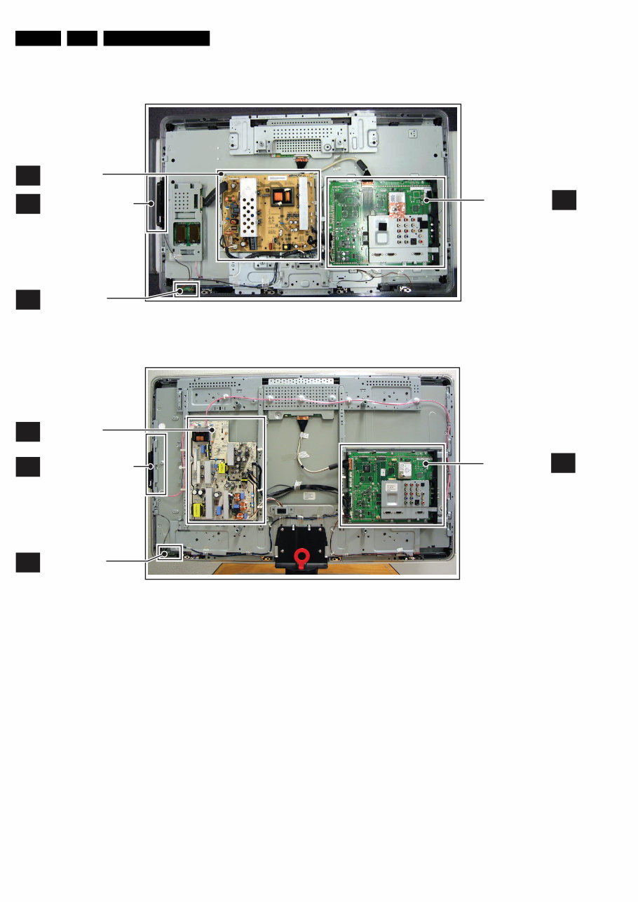
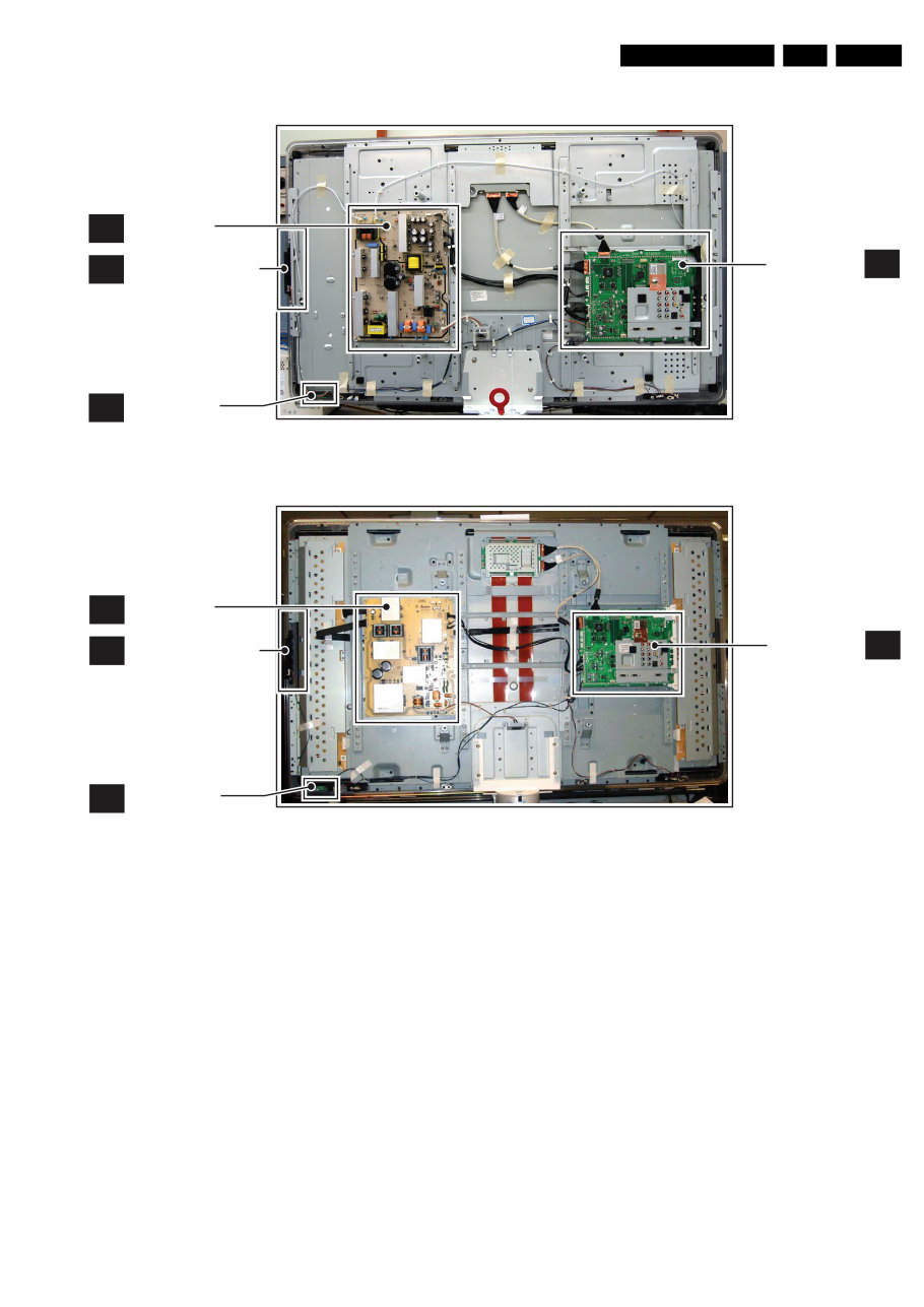
Technical Specifications, Connections, and Chassis Overview EN 4 LC8.1U LA 1. 1.3 Chassis Overview Figure 1-4 PWB/CBA locations 32" models Figure 1-5 PWB/CBA locations 42" models I_17741_016.eps 280108 B MAIN SUPPLY PANEL SMALL SIGNAL BOARD J IR & LED PANEL E A KEYBOARD & CONTROL PANEL H_17650_083.eps 160108 H_17740_041.eps 240108 B MAIN SUPPLY PANEL SMALL SIGNAL BOARD J IR & LED PANEL E A KEYBOARD & CONTROL PANEL
Technical Specifications, Connections, and Chassis Overview EN 5 LC8.1U LA 1. Figure 1-6 PWB/CBA locations 47" models Figure 1-7 PWB/CBA locations 52" models I_17741_017.eps 280108 B MAIN SUPPLY PANEL SMALL SIGNAL BOARD J IR & LED PANEL E A KEYBOARD & CONTROL PANEL I_17741_018.eps 280108 B MAIN SUPPLY PANEL SMALL SIGNAL BOARD J IR & LED PANEL E A KEYBOARD & CONTROL PANEL
Safety Instructions, Warnings, and Notes EN 6 LC8.1U LA 2. 2. Safety Instructions, Warnings, and Notes Index of this chapter: 2.1 Safety Instructions 2.2 Warnings 2.3 Notes 2.1 Safety Instructions Safety regulations require the following during a repair: • Connect the set to the Mains/AC Power via an isolation transformer (> 800 VA). • Replace safety components, indicated by the symbol h, only by components identical to the original ones. Any other component substitution (other than original type) may increase risk of fire or electrical shock hazard. Safety regulations require that after a repair, the set must be returned in its original condition. Pay in particular attention to the following points: • Route the wire trees correctly and fix them with the mounted cable clamps. • Check the insulation of the Mains/AC Power lead for external damage. • Check the strain relief of the Mains/AC Power cord for proper function. • Check the electrical DC resistance between the Mains/AC Power plug and the secondary side (only for sets that have a Mains/AC Power isolated power supply): 1. Unplug the Mains/AC Power cord and connect a wire between the two pins of the Mains/AC Power plug. 2. Set the Mains/AC Power switch to the “on” position (keep the Mains/AC Power cord unplugged!). 3. Measure the resistance value between the pins of the Mains/AC Power plug and the metal shielding of the tuner or the aerial connection on the set. The reading should be between 4.5 Mohm and 12 Mohm. 4. Switch “off” the set, and remove the wire between the two pins of the Mains/AC Power plug. • Check the cabinet for defects, to prevent touching of any inner parts by the customer. 2.2 Warnings • All ICs and many other semiconductors are susceptible to electrostatic discharges (ESD w). Careless handling during repair can reduce life drastically. Make sure that, during repair, you are connected with the same potential as the mass of the set by a wristband with resistance. Keep components and tools also at this same potential. • Be careful during measurements in the high voltage section. • Never replace modules or other components while the unit is switched “on”. • When you align the set, use plastic rather than metal tools. This will prevent any short circuits and the danger of a circuit becoming unstable. 2.3 Notes 2.3.1 General • Measure the voltages and waveforms with regard to the chassis (= tuner) ground (H), or hot ground (I), depending on the tested area of circuitry. The voltages and waveforms shown in the diagrams are indicative. Measure them in the Service Default Mode (see chapter 5) with a color bar signal and stereo sound (L: 3 kHz, R: 1 kHz unless stated otherwise) and picture carrier at 475.25 MHz for PAL, or 61.25 MHz for NTSC (channel 3). • Where necessary, measure the waveforms and voltages with (D) and without (E) aerial signal. Measure the voltages in the power supply section both in normal operation (G) and in stand-by (F). These values are indicated by means of the appropriate symbols. • Manufactured under license from Dolby Laboratories. “Dolby”, “Pro Logic” and the “double-D symbol”, are trademarks of Dolby Laboratories. 2.3.2 Schematic Notes • All resistor values are in ohms, and the value multiplier is often used to indicate the decimal point location (e.g. 2K2 indicates 2.2 kohm). • Resistor values with no multiplier may be indicated with either an “E” or an “R” (e.g. 220E or 220R indicates 220 ohm). • All capacitor values are given in micro-farads (μ= × 10 -6 ), nano-farads (n= × 10 -9 ), or pico-farads (p= × 10 -12 ). • Capacitor values may also use the value multiplier as the decimal point indication (e.g. 2p2 indicates 2.2 pF). • An “asterisk” (*) indicates component usage varies. Refer to the diversity tables for the correct values. • The correct component values are listed in the Spare Parts List. Therefore, always check this list when there is any doubt. 2.3.3 BGA (Ball Grid Array) ICs BGA Temperature Profiles For BGA-ICs, you must use the correct temperature-profile, which is coupled to the 12NC. For an overview of these profiles, contact your local Service organization. 2.3.4 Lead-free Soldering Due to lead-free technology some rules have to be respected by the workshop during a repair: • Use only lead-free soldering tin Philips SAC305 with order code 0622 149 00106. If lead-free solder paste is required, please contact the manufacturer of your soldering equipment. In general, use of solder paste within workshops should be avoided because paste is not easy to store and to handle. • Use only adequate solder tools applicable for lead-free soldering tin. The solder tool must be able: – To reach a solder-tip temperature of at least 400°C. – To stabilize the adjusted temperature at the solder-tip. – To exchange solder-tips for different applications. • Adjust your solder tool so that a temperature of around 360°C - 380°C is reached and stabilized at the solder joint. Heating time of the solder-joint should not exceed ~ 4 sec. Avoid temperatures above 400°C, otherwise wear-out of tips will increase drastically and flux-fluid will be destroyed. To avoid wear-out of tips, switch “off” unused equipment or reduce heat. • Mix of lead-free soldering tin/parts with leaded soldering tin/parts is possible but PHILIPS recommends strongly to avoid mixed regimes. If this cannot be avoided, carefully clear the solder-joint from old tin and re-solder with new tin.
Directions for Use EN 7 LC8.1U LA 3. 2.3.5 Alternative BOM identification The third digit in the serial number (example: AG2B0335000001) indicates the number of the alternative B.O.M. (Bill Of Materials) that has been used for producing the specific TV set. In general, it is possible that the same TV model on the market is produced with e.g. two different types of displays, coming from two different suppliers. This will then result in sets which have the same CTN (Commercial Type Number; e.g. 28PW9515/12) but which have a different B.O.M. number. By looking at the third digit of the serial number, one can identify which B.O.M. is used for the TV set he is working with. If the third digit of the serial number contains the number “1” (example: AG1B033500001), then the TV set has been manufactured according to B.O.M. number 1. If the third digit is a “2” (example: AG2B0335000001), then the set has been produced according to B.O.M. no. 2. This is important for ordering the correct spare parts! For the third digit, the numbers 1...9 and the characters A...Z can be used, so in total: 9 plus 26= 35 different B.O.M.s can be indicated by the third digit of the serial number. Identification: The bottom line of a type plate gives a 14-digit serial number. Digits 1 and 2 refer to the production center (e.g. AG is Bruges), digit 3 refers to the B.O.M. code, digit 4 refers to the Service version change code, digits 5 and 6 refer to the production year, and digits 7 and 8 refer to production week (in example below it is 2006 week 17). The 6 last digits contain the serial number. Figure 2-1 Serial number (example) 2.3.6 Board Level Repair (BLR) or Component Level Repair (CLR) If a board is defective, consult your repair procedure to decide if the board has to be exchanged or if it should be repaired on component level. If your repair procedure says the board should be exchanged completely, do not solder on the defective board. Otherwise, it cannot be returned to the O.E.M. supplier for back charging! 2.3.7 Practical Service Precautions • It makes sense to avoid exposure to electrical shock. While some sources are expected to have a possible dangerous impact, others of quite high potential are of limited current and are sometimes held in less regard. • Always respect voltages. While some may not be dangerous in themselves, they can cause unexpected reactions that are best avoided. Before reaching into a powered TV set, it is best to test the high voltage insulation. It is easy to do, and is a good service precaution. 3. Directions for Use You can download this information from the following websites: http://www.philips.com/support http://www.p4c.philips.com E_06532_024.eps 260308 MODEL : PROD.NO: ~ S 32PF9968/10 MADE IN BELGIUM 220-240V 50/60Hz 128W AG 1A0617 000001 VHF+S+H+UHF BJ3.0E LA
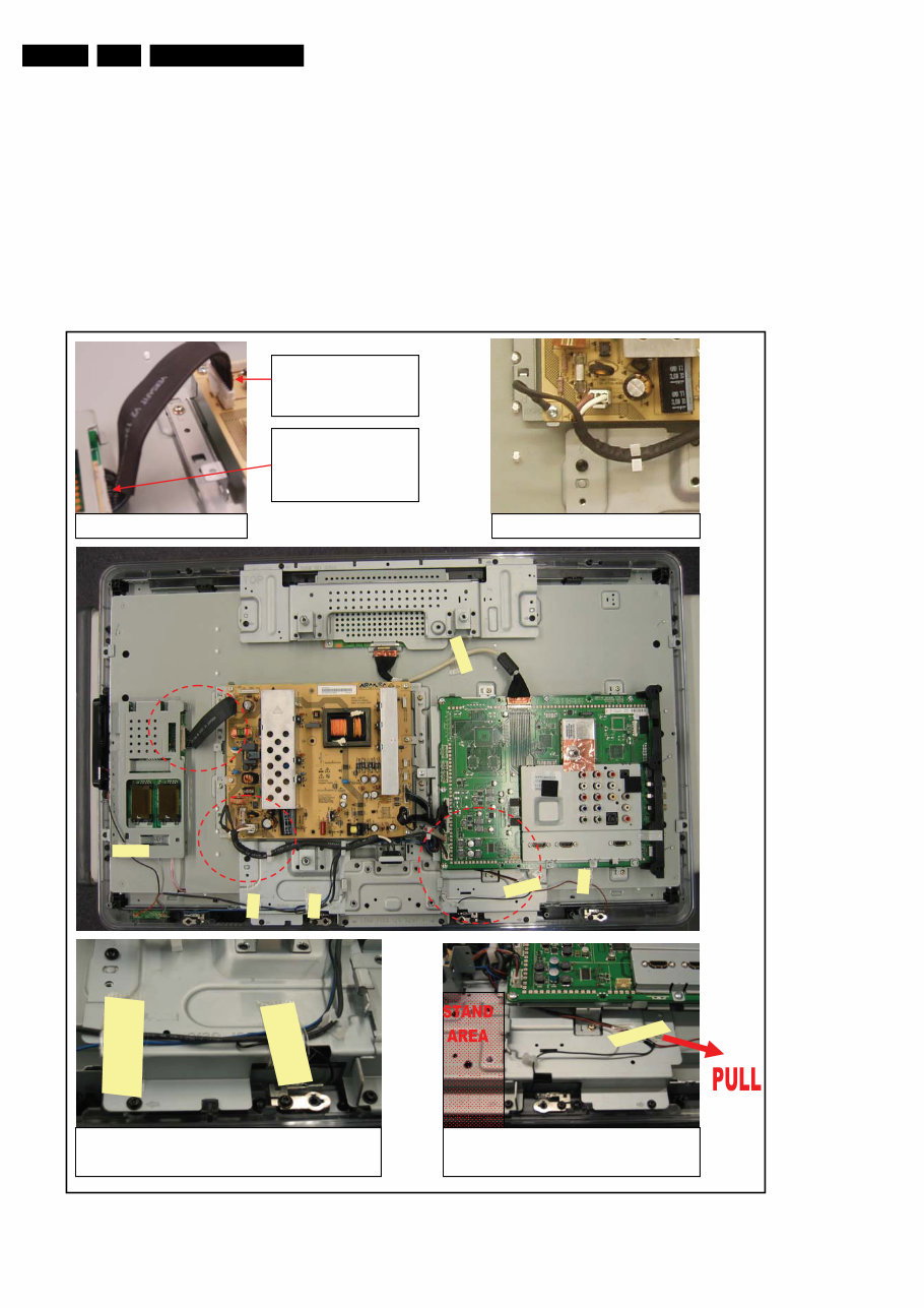
Mechanical Instructions EN 8 LC8.1U LA 4. 4. Mechanical Instructions Index of this chapter: 4.1 Cable Dressing 4.2 Service Positions 4.3 Assy/Panel Removal ME8 Styling 4.4 Set Re-assembly Notes: • Figures below can deviate slightly from the actual situation, due to the different set executions. • Follow the disassemble instructions in described order. • Please pay special attention to the speaker wires when re- assembling the set. Place the cable tapes as shown in next figures. 4.1 Cable Dressing Figure 4-1 Cable dressing (32" models, ME8 styling) CONNECTOR WITH LOCK INSERTED TO PSU CONNECTOR WITHOUT LOCK INSERTED TO PANEL Speaker cable dressing: Pull cable taut underneath SSB Plate before taping to keep out of stand area Inverter Cable AC Mains Cable Speaker and IR cable dressing: Tape to keep out of speaker terminals I_17741_009.eps 280408
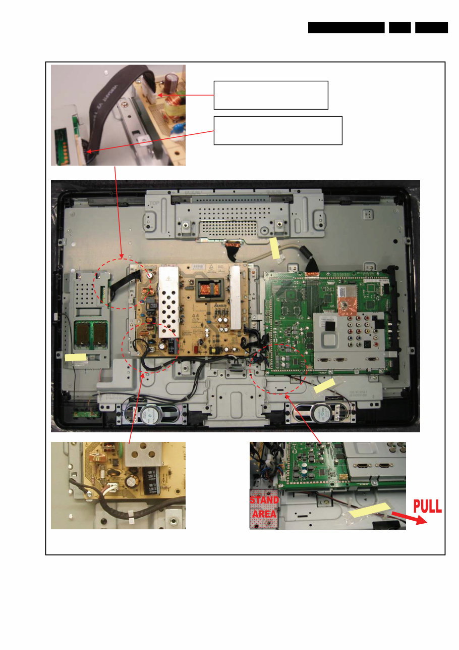
Mechanical Instructions EN 9 LC8.1U LA 4. Figure 4-2 Cable dressing (32" models, MG8 styling) AC Mains Shield wire to be grounded to Detailed view of speaker cable dressing: bottom corner of PSU with screw Pull cable taut underneath SSB Plate before CONNECTOR WITH LOCK INSERTED TO PSU CONNECTOR WITHOUT LOCK INSERTED TO PANEL I_17741_008.eps 240408
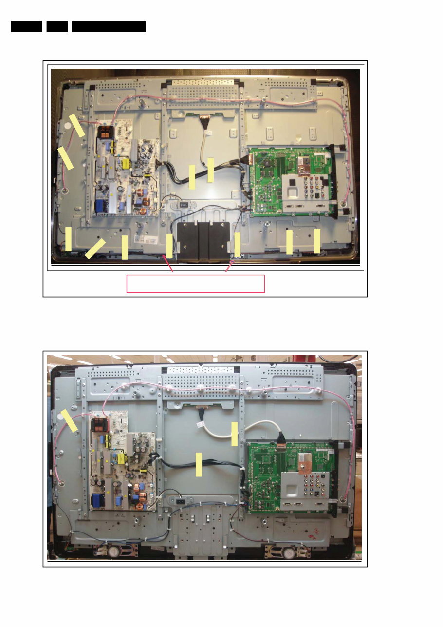
Mechanical Instructions EN 10 LC8.1U LA 4. Figure 4-3 Cable dressing (42" models, ME8 styling) Figure 4-4 Cable dressing (42" models, MG8 styling) Tape tweeter wire to metal frame (both ends) to keep away from tweeter terminal I_17741_010.eps 240408 I_17741_011.eps 240408
Why replace when you can upgrade or repair? This service and repair manual is used by the Official Certified Philips Technicians. It will help you to troubleshoot and repair your LCD TV!
You will learn about:
Product Operations & Technical Specifications
Mechanical Instructions
Disassembly Instructions
Service Modes & Error Codes
Troubleshooting
Alignments
Software Upgrading
Block Diagram
Circuit Diagram
IC Data Sheets & PWB Layouts
Exploded Views
This service manual is very detailed and illustrated with pictures and step-by-step instructions on how to repair/service this device the best way there is! Please note this is the OFFICIAL and COMPLETE service repair manual in .PDF format, no scanned-in or bootlegged copy. This manual is made in the highest resolution, so when you print the pages you need it is all in great quality!
You can easily print this service manual from any printer and any computer!
***INSTANT access*** After your payment, you will have instant access to your manual. No shipping fee, no waiting on postal delivery, you can start doing your repairs today!
Specifications
Language: English
Format: .PDF
Platform: Windows and MAC
Looking for a service manual but can't find it anywhere? Please contact us with your request! As you can see we've got the largest & most comprehensive service manual database out there, so a good chance we can help you out!





 Lifetime Access




