

© Panasonic Corporation 2012.
Unauthorized copying and distribution is a violation
of law.
ORDER NO.MTNC120424CE
B34 Canada: B62
55 inch Class 1080p Plasma HDTV
Model No. TC-P55VT50
GPF15DU Chassis
For detailed troubleshooting information and circuit explanations,
refer to the "QSM/Service Hints/Troubleshooting Information(TI)" and Seminar/Training Manual/Technical
Guide(TG) documents posted on the TSN web site.
For information about this model, type TC-P2012 in the model box under "Direct Search".

2
TABLE OF CONTENTS
PAGE PAGE
1 Safety Precautions ----------------------------------------------- 3
1.1. General Guidelines ----------------------------------------3
2 Warning -------------------------------------------------------------- 4
2.1. Prevention of Electrostatic Discharge (ESD)
to Electrostatically Sensitive (ES) Devices ----------4
2.2. About lead free solder (PbF) ----------------------------5
3 Service Navigation------------------------------------------------ 6
3.1. PCB Layout--------------------------------------------------6
4 Specifications ------------------------------------------------------ 7
5 Technical Descriptions ------------------------------------------ 8
5.1. Specification of KEY for DTCP-IP, WMDRM
and Widevine------------------------------------------------8
6 Service Mode ------------------------------------------------------- 9
6.1. How to enter into Service Mode ------------------------9
6.2. Option - Mirror--------------------------------------------- 11
6.3. Service tool mode ---------------------------------------- 11
6.4. Hotel mode------------------------------------------------- 12
6.5. Data Copy by SD Card --------------------------------- 13
7 Troubleshooting Guide---------------------------------------- 16
8 Service Fixture & Tools --------------------------------------- 17
8.1. SC jig -------------------------------------------------------- 17
9 Disassembly and Assembly Instructions --------------- 18
9.1. Disassembly Flow Chart for the Unit ---------------- 18
9.2. Disassembly Procedure for the Unit----------------- 19
10 Measurements and Adjustments -------------------------- 26
10.1. Adjustment------------------------------------------------- 26
11 Block Diagram --------------------------------------------------- 29
11.1. Main Block Diagram ------------------------------------- 29
11.2. Block (1/4) Diagram ------------------------------------- 30
11.3. Block (2/4) Diagram ------------------------------------- 31
11.4. Block (3/4) Diagram ------------------------------------- 32
11.5. Block (4/4) Diagram ------------------------------------- 33
12 Wiring Connection Diagram --------------------------------- 35
12.1. Caution statement.--------------------------------------- 35
12.2. Wiring (1)--------------------------------------------------- 35
12.3. Wiring (2)--------------------------------------------------- 36
12.4. Wiring (3)--------------------------------------------------- 37
12.5. Wiring (4)--------------------------------------------------- 37
12.6. Wiring (5)--------------------------------------------------- 38
12.7. Wiring (6)--------------------------------------------------- 38
12.8. Wiring (7)--------------------------------------------------- 39
13 Schematic Diagram
14 Printed Circuit Board
15 Exploded View
3
1 Safety Precautions
1.1. General Guidelines
1. When conducting repairs and servicing, do not attempt to modify the equipment, its parts or its materials.
2. When wiring units (with cables, flexible cables or lead wires) are supplied as repair parts and only one wire or some of the
wires have been broken or disconnected, do not attempt to repair or re-wire the units. Replace the entire wiring unit instead.
3. When conducting repairs and servicing, do not twist the Fasten connectors but plug them straight in or unplug them straight
out.
4. When servicing, observe the original lead dress. If a short circuit is found, replace all parts which have been overheated or
damaged by the short circuit.
5. After servicing, see to it that all the protective devices such as insulation barriers, insulation papers shields are properly
installed.
6. After servicing, make the following leakage current checks to prevent the customer from being exposed to shock hazards.
1.1.1. Leakage Current Cold Check
1. Unplug the AC cord and connect a jumper between the
two prongs on the plug.
2. Measure the resistance value, with an ohmmeter,
between the jumpered AC plug and each exposed
metallic cabinet part on the equipment such as
screwheads, connectors, control shafts, etc. When the
exposed metallic part has a return path to the chassis, the
reading should be between 1Mohm and 5.2Mohm.
When the exposed metal does not have a return path to
the chassis, the reading must be .
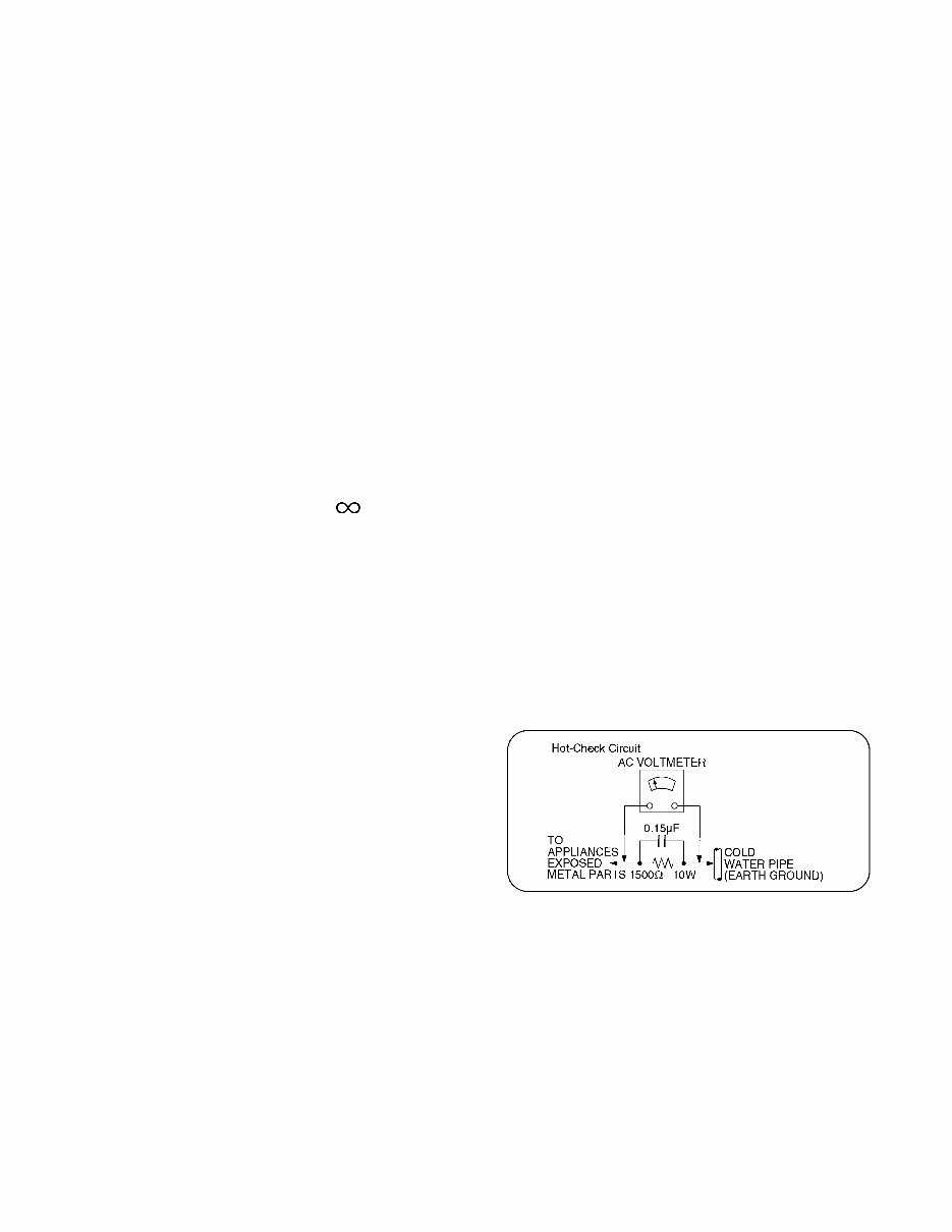
1.1.2. Leakage Current Hot Check (See
Figure 1.)
1. Plug the AC cord directly into the AC outlet. Do not use
an isolation transformer for this check.
2. Connect a 1.5kohm, 10 watts resistor, in parallel with a
0.15μF capacitors, between each exposed metallic part
on the set and a good earth ground such as a water pipe,
as shown in Figure 1.
3. Use an AC voltmeter, with 1000 ohms/volt or more
sensitivity, to measure the potential across the resistor.
4. Check each exposed metallic part, and measure the
voltage at each point.
5. Reverse the AC plug in the AC outlet and repeat each of
the above measurements.
6. The potential at any point should not exceed 0.75 volts
RMS. A leakage current tester (Simpson Model 229 or
equivalent) may be used to make the hot checks, leakage
current must not exceed 1/2 milliamp. In case a
measurement is outside of the limits specified, there is a
possibility of a shock hazard, and the equipment should
be repaired and rechecked before it is returned to the
customer.
Figure 1

4
2 Warning
2.1. Prevention of Electrostatic Discharge (ESD) to Electrostatically
Sensitive (ES) Devices
Some semiconductor (solid state) devices can be damaged easily by static electricity. Such components commonly are called
Electrostatically Sensitive (ES) Devices. Examples of typical ES devices are integrated circuits and some field-effect transistors and
semiconductor [chip] components. The following techniques should be used to help reduce the incidence of component damage
caused by electrostatic discharge (ESD).
1. Immediately before handling any semiconductor component or semiconductor-equipped assembly, drain off any ESD on your
body by touching a known earth ground. Alternatively, obtain and wear a commercially available discharging ESD wrist strap,
which should be removed for potential shock reasons prior to applying power to the unit under test.
2. After removing an electrical assembly equipped with ES devices, place the assembly on a conductive surface such as
aluminum foil, to prevent electrostatic charge buildup or exposure of the assembly.
3. Use only a grounded-tip soldering iron to solder or unsolder ES devices.
4. Use only an anti-static solder removal device. Some solder removal devices not classified as [anti-static (ESD protected)] can
generate electrical charge sufficient to damage ES devices.
5. Do not use freon-propelled chemicals. These can generate electrical charges sufficient to damage ES devices.
6. Do not remove a replacement ES device from its protective package until immediately before you are ready to install it. (Most
replacement ES devices are packaged with leads electrically shorted together by conductive foam, aluminum foil or
comparable conductive material).
7. Immediately before removing the protective material from the leads of a replacement ES device, touch the protective material
to the chassis or circuit assembly into which the device will be installed.
Caution
Be sure no power is applied to the chassis or circuit, and observe all other safety precautions.
8. Minimize bodily motions when handling unpackaged replacement ES devices. (Otherwise ham less motion such as the
brushing together of your clothes fabric or the lifting of your foot from a carpeted floor can generate static electricity (ESD)
sufficient to damage an ES device).
5
2.2. About lead free solder (PbF)
Note: Lead is listed as (Pb) in the periodic table of elements.
In the information below, Pb will refer to Lead solder, and PbF will refer to Lead Free Solder.
The Lead Free Solder used in our manufacturing process and discussed below is (Sn+Ag+Cu).
That is Tin (Sn), Silver (Ag) and Copper (Cu) although other types are available.
This model uses Pb Free solder in it's manufacture due to environmental conservation issues. For service and repair work, we'd
suggest the use of Pb free solder as well, although Pb solder may be used.
PCBs manufactured using lead free solder will have the PbF within a leaf Symbol PbF stamped on the back of PCB.
Caution
• Pb free solder has a higher melting point than standard solder. Typically the melting point is 50 ~ 70 °F (30~40 °C) higher. Please
use a high temperature soldering iron and set it to 700 ± 20 °F (370 ± 10 °C).
• Pb free solder will tend to splash when heated too high (about 1100 °F or 600 °C).
If you must use Pb solder, please completely remove all of the Pb free solder on the pins or solder area before applying Pb
solder. If this is not practical, be sure to heat the Pb free solder until it melts, before applying Pb solder.
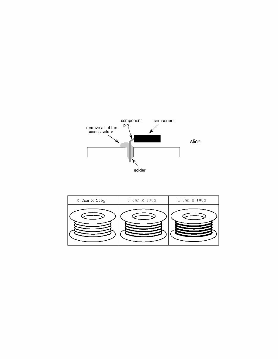
• After applying PbF solder to double layered boards, please check the component side for excess solder which may flow onto the
opposite side. (see figure below)
Suggested Pb free solder
There are several kinds of Pb free solder available for purchase. This product uses Sn+Ag+Cu (tin, silver, copper) solder.
However, Sn+Cu (tin, copper), Sn+Zn+Bi (tin, zinc, bismuth) solder can also be used.
6
3 Service Navigation
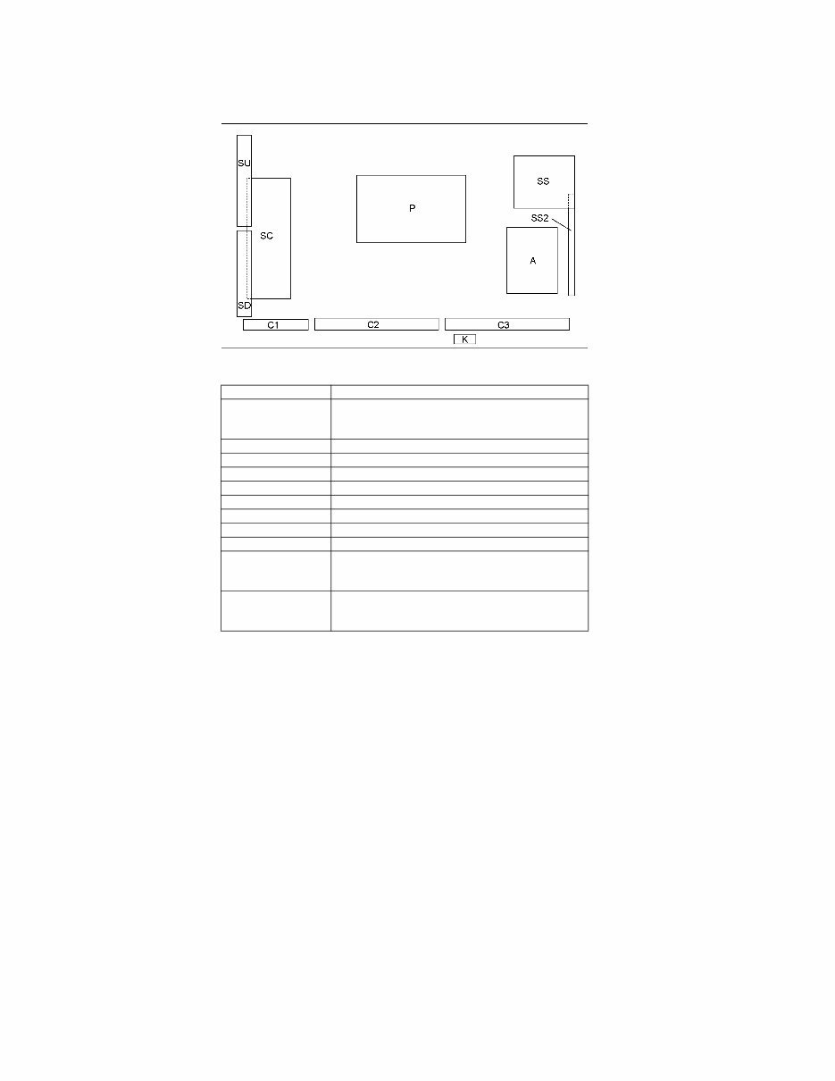
3.1. PCB Layout
Board Name Function
P Power Supply
Non serviceable.
P-Board should be exchanged for service.
A Main AV input, processing
K Remote receiver, Power LED, C.A.T.S sensor
C1 Data Driver (Lower Right)
C2 Data Driver (Lower Center)
C3 Data Driver (Lower Left)
SC Scan Drive
SS Sustain Drive
SS2 Sustain out (Lower)
SU Scan out (Upper)
Non serviceable.
SU-Board should be exchanged for service.
SD Scan out (Lower)
Non serviceable.
SD-Board should be exchanged for service.

7
4 Specifications
TV
Wireless LAN
Bluetooth
Note
Design and Specifications are subject to change without notice. Mass and Dimensions shown are approximate.
Power Source AC 120 V, 60 Hz
Power Consumption
Rated Power 469 W
Standby Power 0.2 W
Display Panel
Panel System Plasma Display panel
Screen size 55 inch class (55.1 inches measured diagonally)
W × H × Diagonal 48.0 inch × 27.0 inch × 55.1 inch (1,221 mm × 686 mm × 1,401 mm)
Number of pixels 1920 × 1080
Speaker Output 18 W [4 W + 4 W + 10 W] (10 % THD)
Channel Capability (Digital/Analog) VHF/ UHF: 2 - 69, CATV: 1 - 135
Operating Conditions
Temperature: 32 °F - 104 °F (0 °C - 40 °C)
Humidity: 20 % - 80 % RH (non-condensing)
Connection Terminals
VIDEO IN RCA PIN (VIDEO, AUDIO-L, AUDIO-R)
COMPONENT IN RCA PIN (Y, PB, PR, AUDIO-L, AUDIO-R)
HDMI IN 1/2/3/4 TYPE A Connector (supports [HDAVI Control 5] function)
USB 1/2/3 USB2.0 Type A connector
DIGITAL AUDIO OUT PCM / Dolby Digital, Fiber Optic
PC IN D-SUB 15 PIN (VGA, SVGA, WVGA, XGA, SXGA, WXGA)
OTHERS SD CARD slot, ETHERNET (10BASE-T/100BASE-TX)
Dimensions (W × H × D)
Including pedestal 50.7 inch × 32.3 inch × 14.1 inch (1,286 mm × 819 mm × 357 mm)
TV Set only 50.7 inch × 30.4 inch × 2.0 inch (1,286 mm × 771 mm × 50 mm)
Mass
Including pedestal 79.4 lb. (36.0 kg) NET
TV Set only 69.5 lb. (31.5 kg) NET
Standard Compliance and
Frequency Range *
1,
*
2
IEEE 802.11a/n :
5.15 GHz - 5.35 GHz, 5.47 GHz - 5.85 GHz
IEEE 802.11b/g/n :
2.400 GHz - 2.4835 GHz
Access Mode Infrastructure mode
Security WPA2-PSK (TKIP/AES)
WPA-PSK (TKIP/AES)
WEP (64bit/128bit)
*
1
The frequency and channel differ depending on the country.
*
2
802.11b/g/n CH1 ~ CH11 only use for United States and Canada.
Standard Compliance
Bluetooth
®
3.0
Frequency Range 2.402GHz~2.480GHz
• Use Panasonic 3D Eyewear supporting Bluetooth wireless technology.
• Up to 5 devices can be used simultaneously (except the Touch Pad Controller and the 3D Eyewear).

8
5 Technical Descriptions
5.1. Specification of KEY for DTCP-IP, WMDRM and Widevine
5.1.1. General information:
1. EEPROM (IC8902) for spare parts has the seed of KEY for each DTCP-IP for DLNA, WMDRM for Netflix and Widevine for
CinemaNow.
2. The final KEY data will be generated by Peaks IC (IC8000) when SELF CHECK was done and are stored in both Peaks IC
(IC8000) and EEPROM (IC8902).
5.1.2. Replacement of ICs:
When Peaks IC is replaced, EEPROM should be also replaced with new one the same time.
When EEPROM is replaced, Peaks IC is not necessary to be replaced the same time.
After the replacement of IC, SELF CHECK should be done to generate the final KEY data.
How to SELF CHECK: While pressing [VOLUME ( - )] button on the main unit, press [MENU] button on the remote control for
more than 3 seconds.
TV will be forced to the factory shipment setting after this SELF CHECK.
9
6 Service Mode
6.1. How to enter into Service Mode
6.1.1. Purpose
After exchange parts, check and adjust the contents of adjustment mode.
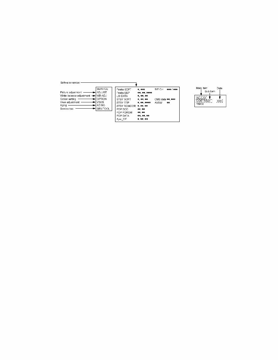
While pressing [VOLUME ( - )] button of the main unit, press [INFO] button of the remote control three times within 2 seconds
Note:
Service Mode can not be entered when 3D signal input.
Input 2D signal to enter Service Mode.
6.1.2. Key command
[1] button...Main items Selection in forward direction
[2] button...Main items Selection in reverse direction
[3] button...Sub items Selection in forward direction
[4] button...Sub items Selection in reverse direction
[VOL] button...Value of sub items change in forward direction ( + ), in reverse direction ( - )
6.1.3. How to exit
Switch off the power with the [POWER] button on the main unit or the [POWER] button on the remote control.

10
6.1.4. Contents of adjustment mode
• Value is shown as a hexadecimal number.
• Preset value differs depending on models.
• After entering the adjustment mode, take note of the value in each item before starting adjustment.
Main item Sub item Sample Data Remark
ADJUST CONTRAST 000
COLOR 3C
TINT 00
SUB-BRT 800
WB-ADJ R-CUT 80
G-CUT 80
B-CUT 80
R-DRV DF
G-DRV FF
B-DRV 7C
ALL-CUT 80
ALL-DRV FF
OPTION Boot ROM Factory Preset
STBY-SET 00
EMERGENCY OFF
CLK MODE 00
CLOCK 000
EDID-CLK HIGH
MIRROR 00 (See Option-Mirror)
VSUS LOW See Vsus selection
AGING ALL WHITE Built-in test patterns can be
displayed. MIDDLE BLUE WITH MAGENTA OUTSIDE FRAME
MIDDLE STEP GREEN
MIDDLE STEP RED
LOW STEP WHITE
ALL BLUE
ALL GREEN
ALL RED
WHITE DIAGONAL STRIPE
RED DIAGONAL STRIPE
GREEN DIAGONAL STRIPE
BLUE DIAGONAL STRIPE
A-ZONE & B-ZONE
1% WINDOW
COLOR BAR
9 POINTS BRIGHT MEASURE
2 DOT OUTSIDE FRAME
DOUBLE FIXED 1% WINDOW
VERTICAL LINE SCROLL
ON/OFF
R/G/B/W ROTATION WITH COUNT DISPLAY
HALF FIXED ALL WHITE
ALL WHITE WITH COUNT DISPLAY
SRV-TOOL 00 See Service tool mode
You're Reading a Preview
What's Included?
 Lifetime Access
Fast Download Speeds
Online & Offline Access
Access PDF Contents & Bookmarks
Full Search Facility
Print one or all pages of your manual
$35.99
Panasonic TC-P55VT50 55-inch Class 1080p Plasma HDTV OEM Service & Repair Manual
Viewed 78 Times Today

What's Included?
Lifetime Access
Fast Download Speeds
Online & Offline Access
Access PDF Contents & Bookmarks
Full Search Facility
Print one or all pages of your manual
$35.99

Secure transaction
What's Included?
Lifetime Access
Fast Download Speeds
Online & Offline Access
Access PDF Contents & Bookmarks
Full Search Facility
Print one or all pages of your manual
Description
This official factory service, repair, and workshop manual is essential for troubleshooting and repairing your Panasonic TC-P55VT50, a 55-inch Class 1080p Plasma HDTV. It is designed to provide certified Panasonic technicians and maintenance employees with the reliable guidance needed for efficient repairs and servicing.
Features include:
- In-depth technical descriptions covering servicing precautions, detailed inspections, and recommended service tools.
- Step-by-step guidance on adjustments, troubleshooting, disassembly, and repairs.
- Comprehensive wiring diagrams, block diagrams, schematic diagrams, and a complete parts list catalog.
- The official service manual is delivered in high-resolution PDF format, ideal for precise printing and easy reference.
- Instant digital access eliminates shipping fees and delays, allowing for immediate repair readiness.
Specifications:
- Language: English
- Format: PDF
- Platform: Windows and MAC
This detailed manual is trusted by Panasonic professionals for its accuracy and clear, step-by-step instructions, ensuring the proper approach to repairing, servicing, and maintaining your Panasonic TC-P55VT50 HDTV.


