

Panasonic TX-L LCD Televisions (TX-L32E30E/TX-LF32E30/TX-LR32E30/TX-L37E30E/TX-LF37E30) OEM Service & Repair Manual
What's Included?
Fast Download Speeds
Online & Offline Access
Access PDF Contents & Bookmarks
Full Search Facility
Print one or all pages of your manual
Service Manual
LCD Television
TX-L32E30E
TX-LF32E30
TX-LR32E30
TX-L37E30E
TX-LF37E30
LA18 Chassis
Specifications
(Information in brackets [ ] refers to model 32”)
Power Source: 220-240V AC, 50 / 60Hz
Rated Power Consumption: 85W [72W]
Stand-by Power Consumption: 0.3W (Without monitor out recording)
14W (With monitor out recording)
Aerial Impedance: 75 unbalanced, Coaxial Type
Receiving System: DVB-T (Digital Terrestrial Services (MPEG2 and MPEG4-AVC(H.264))
DVB-C (Digital cable services (MPEG2 and MPEG4-AVC(H.264))
PAL-I/H, B/G, D/K
SECAM B/G, D/K, L/L’
PAL-525/60 (AV only)
M.NTSC (AV only)
NTSC (AV only)
Receiving Chanels: VHF E2-E12 VHF H1-H2 ( ITALY )
VHF A-H ( ITALY ) UHF E21-E69
CATV (S01-S05) CATV S1-S10(M1-M10)
CATV S11-S20 (U1-U10) CATV S21-S41 (HYPERBAND)
VHF R1-R2 VHF R3-R5
VHF R6-R12
Aerial - Rear: VHF/UHF
Operating Conditions: Temperature: 0°C 35°C
Humidity: 20% 80% RH (non condensing)
© Panasonic Corporation 2011.
Unauthorized copying and
distribution is a violation of law.
ORDER No. PCZ1102007CE

Intermediate Frequency:
Video/Audio
Video 38.9MHz, 33.9MHz
Audio 33.4MHz (B/G), 33.16MHz (A2)
33.05MHz (NICAM B/G, D/K, L)
32.4MHz (D/K), 32.66MHz (CZ STEREO)
40.4MHz (L’), 39.75MHz (L’NICAM)
Colour 34.47MHz (PAL)
34.5MHz, 34.65MHz (SECAM)
38.3MHz, 38.15MHz (SECAM L’)
Terminals:
AV1 IN Video (21 pin) 1V p-p 75
Audio (21 pin) 500mV rms 10k
RGB (21 pin) 0.7V p-p 75
AV1 OUT Video (21 pin) 1V p-p 75
Audio (21 pin) 500mV rms 1k
AV2 IN Video (RCAx1) 1V p-p 75
AUDIO IN Audio (RCAx2) 500mV rms 10k (used for HDMI4_AV2 Audio IN)
COMPONENT Video (RCAx3) Y:1V p-p 75 (including synchronization)
Pb, Pr: ±0.35V p-p 75
AUDIO IN Audio (RCAx2) 500mV rms 10k (used for HDMI1/2/3_Component Audio IN)
HDMI, HDMI2, HDMI3, HDMI4 Type A Connectors
HDMI 1/3/4 :HDMI (Version 1.4 with Content Type) Deep Colour
HDMI 2 :HDMI (Version 1.4 with Content Type, Audio Return Channel) Deep Colour
This TV supports “HDAVI Control 5” function.
AUDIO OUT Audio (RCAx2) 500mV rms 1k (high impedance)
DIGITAL AUDIO OUT PCM / Dolby digital / DTS, Fiber optic
USB 1/2/3 USB 2.0 DC 5V Max 500mA
PC HIGH-DENSITY D_SUB 15PIN R,G,B: 700mV p-p 75
HD,VD/TTL Level 2-5V p-p (high impedance)
ETHERNET RJ45, IEEE802.3 10BASE-T / 100BASE-TX
E30E, LFE30 LRE30
CARD SLOT SD CARD slot x1 SD CARD slot x1
Common interface (Complies with CI+)slot x1 Common interface slot x1
LCD screen: VVX37F115G00 [VVX32F115G00]
1920 x 1080, 16:9
Visible Diagonal 940mm [800mm]
Audio Output: 20W (2 x 10W), 10% THD
Headphones: 3.5mm, 8 Impedance
Accessories supplied : Remote Control 2 x R6 (UM3) Batteries
Dimensions:
Height: Width: Depth:
Including TV stand 582mm 890mm 260mm
[514mm 769mm 230mm]
TV set only 548mm 890mm 75mm
[480mm 769mm 75mm]
Mass:
Including TV stand 15.0kg [12.5kg]
TV set only 12.5kg [10.0kg]
Specifications are subject to change without notice.
Mass and dimensions shown are approximate.
This service information is designed for experienced repair technicians only and is not designed for use by the general public. It does not
contain warnings or cautions to advise non-technical individuals of potencial dangers in attempting to service a product. Products
powered by electricity should be serviced or repaired only by experienced professional technicians. Any attempt to service or repair the
product or products deal within this service information by anyone else could result in serious injury or death.
Warning

CONTENTS
SAFETY PRECAUTIONS ........................................... 4
GENERAL GUIDE LINES...................................... 4
TOUCH – CURRENT CHECK............................... 4
PREVENTION OF ELECTROSTATIC DISCHARGE
(ESD) TO ELECTROSTATICALLY SENSITIVE (ES)
DEVICES .................................................................... 5
ABOUT LEAD FREE SOLDER (PBF) ......................... 6
SUGGESTED PB FREE SOLDER ........................ 6
APPLICABLE SIGNALS.............................................. 7
SERVICE HINTS ........................................................ 8
CHASSIS BOARD LAYOUT ....................................... 9
LOCATION OF LEAD WIRING ................................... 9
TECHNICAL DESCRIPTION ................................ ….10
SPECIFICATION OF KEY FOR CI PLUS,
DTCP-IP, ONE-TO-ONE AND WIDEVINE .......... 10
GENERAL INFORMATION ................................. 10
REPLACEMENT OF ICS..................................... 10
MODEL AND KEYS ............................................ 10
SETTING INSPECTION............................................ 11
SELF CHECK ........................................................... 12
HOTEL MODE .......................................................... 18
DATA COPY BY SD CARD....................................... 19
DATA COPY FROM TV SET TO SD CARD ............. 20
DATA COPY FROM SD CARD TO TV SET ............. 21
OPTION BYTES DESCRIPTION .............................. 22
ADJUSTMENT METHOD.......................................... 23
WIRING DIAGRAM ................................................... 24
BLOCK DIAGRAM (1 OF 2) ...................................... 25
PARTS LOCATION ................................................... 27
REPLACEMENT PARTS LIST .................................. 29
SCHEMATIC DIAGRAMS ......................................... 41
A-BOARD (1 OF 18) SCHEMATIC DIAGRAM .... 42
P-BOARD (1 OF 2) SCHEMATIC DIAGRAM ...... 60
LD-BOARD (1 OF 2) SCHEMATIC DIAGRAM .... 62
KA-BOARD.......................................................... 63
CONDUCTOR VIEWS .............................................. 64
POWER LED BLINKING TIMING CHART ................ 14
SERVICE MODE FUNCTION ................................... 15
SERVICE ................................................................ 16
SERVICE TOOL MODE............................................ 17
Safety Precautions
General Guide Lines
1. When servicing, observe the original lead dress. If a short circuit is found, replace all parts which have been overheated
or damaged by the short circuit.
2. After servicing, see to it that all the protective devices such as insulation barriers, insulation papers shields are properly
installed.
3. After servicing, make the following touch current checks to prevent the customer from being exposed to shock hazards.
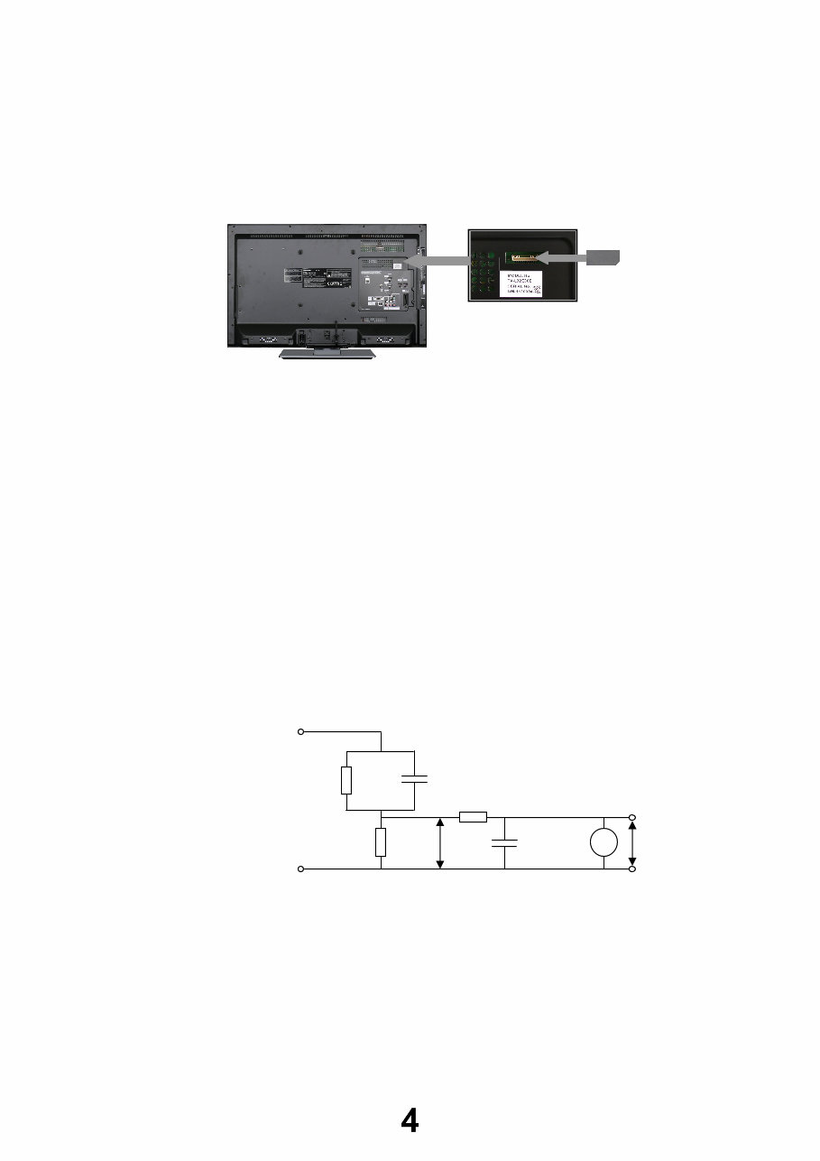
4. Always ensure cover label TBM4GU113 is correctly replaced before returning to customer (see Fig.1).
Touch-Current Check
1. Plug the AC cord directly into the AC outlet. Do not use an isolation transformer for this check.
2. Connect a measuring network for touch currents between each exposed metallic part on the set and a good earth
ground such as a water pipe, as shown in Fig. 2.
3. Use Leakage Current Tester (Simpson 228 or equivalent) to measure the potential across the measuring network.
4. Check each exposed metallic part, and measure the voltage at each point.
5. Reserve the AC plug in the AC outlet and repeat each of the above measure.
6. The potential at any point (TOUCH CURRENT) expressed as voltage U1 and U2, does not exceed the following values:
For a. c.: U1 = 35 V (peak) and U2 = 0.35 V (peak);
For d. c.: U1 = 1.0 V,
Note:
The limit value of U2 = 0.35 V (peak) for a. c. and U1 = 1.0 V for d. c. correspond to the values 0.7 mA (peak) a. c. and
2.0 mA d. c.
The limit value U1 = 35 V (peak) for a. c. correspond to the value 70 mA (peak) a. c. for frequencies greater than 100
kHz.
7. In case a measurement is out of the limits specified, there is a possibility of a shock hazard, and the equipment should
be repaired and rechecked before it is returned to the customer.
Fig. 2
TO
APPLIANCES
EXPOSED
METAL PARTS
Resistance values in ohms ()
V
R
0
=500
R
S
=1500 C
S
=0.22F
10k
0.022F
COLD
WATER PIPE
(EARTH GROUND)
V: Voltmetr or oscilloscope
(r.m.s. or peak reading)
Measuring network for TOUCH CURRENTS
Input resistance: 1M
Input capacitance: 200pF
Frequency range: 15Hz to 1MHz and d.c.respectively
NOTE – Appropriate measures should be taken to obtain the correct value in case of non-sinusoidal waveforms
U
2
(V)
Fig. 1
U
1
(V)

Prevention of Electrostatic Discharge (ESD) to Electrostatically
Sensitive (ES) Devices
Some semiconductor (solid state) devices can be damaged easily by static electricity. Such components commonly are
called Electrostatically Sensitive (ES) Devices. Examples of typical ES devices are integrated circuits and some field-effect
transistors and semiconductor "chip" components. The following techniques should be used to help reduce the incidence of
component damage caused by electrostatic discharge (ESD).
1. Immediately before handling any semiconductor component or semiconductor-equipped assembly, drain off any ESD on
your body by touching a known earth ground. Alternatively, obtain and wear a commercially available discharging ESD
wrist strap, which should be removed for potential shock reasons prior to applying power to the unit under test.
2. After removing an electrical assembly equipped with ES devices, place the assembly on a conductive surface such as
aluminum foil, to prevent electrostatic charge build up or exposure of the assembly.
3. Use only a grounded-tip soldering iron to solder or unsolder ES devices.
4. Use only an anti-static solder removal device. Some solder removal devices not classified as "anti-static (ESD
protected)" can generate electrical charge sufficient to damage ES devices.
5. Do not use freon-propelled chemicals. These can generate electrical charges sufficient to damage ES devices.
6. Do not remove a replacement ES device from its protective package until immediately before you are ready to install it.
(Most replacement ES devices are packaged with leads electrically shorted together by conductive foam, aluminum foil
or comparable conductive material).
7. Immediately before removing the protective material from the leads of a replacement ES device, touch the protective
material to the chassis or circuit assembly into which the device will be installed.
Caution
Be sure no power is applied to the chassis or circuit, and observe all other safety precautions.
8. Minimize bodily motions when handling unpackaged replacement ES devices. (Otherwise harmless motion such as the
brushing together of your clothes fabric or the lifting of your foot from a carpeted floor can generate static electricity
(ESD) sufficient to damage an ES device).
There are special components used in this equipment which are important for safety.
These parts are marked by in schematic diagrams, exploded views and replacement parts list. It is essential that
these critical parts should be replaced with manufacturer’s specified parts to prevent shock, fire, or other hazards. Do
not modify the original design without permission of manufacturer.
IMPORTANT SAFETY NOTICE
About lead free solder (PbF)
Note: Lead is listed as (Pb) in the periodic table of elements.
In the information below, Pb will refer to Lead solder, and PbF will refer to Lead Free Solder.
The Lead Free Solder used in our manufacturing process and discussed below is (Sn+Ag+Cu).
That is Tin (Sn), Silver (Ag) and Copper (Cu) although other types are available.
This model uses Pb Free solder in it’s manufacture due to environmental conservation issues. For service and repair work,
we’d suggest the use of Pb free solder as well, although Pb solder may be used.
PCBs manufactured using lead free solder will have the PbF within a leaf Symbol
stamped on the back of PCB.
Caution
Pb free solder has a higher melting point than standard solder. Typically the melting point is 50 ~ 70 °F (30~40°C)
higher. Please use a high temperature soldering iron and set it to 700 ± 20 °F (370 ± 10 °C).
Pb free solder will tend to splash when heated too high (about 1100 °F or 600 °C).
If you must use Pb solder, please completely remove all of the Pb free solder on the pins or solder area before
applying Pb solder. If this is not practical, be sure to heat the Pb free solder until it melts, before applying Pb solder.
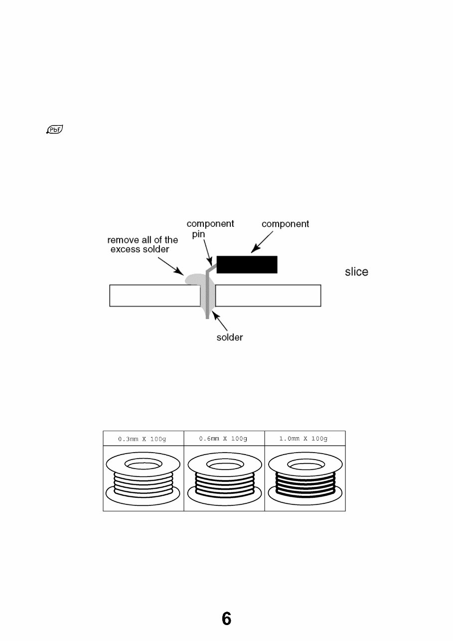
After applying PbF solder to double layered boards, please check the component side for excess solder which may
flow onto the opposite side. (see Fig.3)
Suggested Pb free solder
There are several kinds of Pb free solder available for purchase. This product uses Sn+Ag+Cu (tin, silver, copper) solder.
However, Sn+Cu (tin, copper), Sn+Zn+Bi (tin, zinc, bismuth) solder can also be used. (see Fig.4)
Fig.3
Fig.4
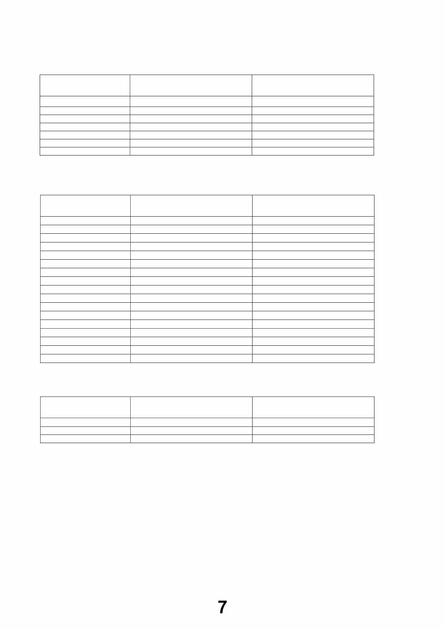
Applicable Signals
Applicable input signal for PC is basically compatible to VESA standard timing.
Signal name Horizontal frequency (kHz) Vertical frequency (Hz)
640 400 @70 Hz 31.47 70.07
640 480 @60 Hz 31.47 59.94
640 480 @75 Hz 37.50 75.00
800 600 @60 Hz 37.88 60.32
800 600 @75 Hz 46.88 75.00
800 600 @85 Hz 53.67 85.06
852 480 @60Hz 31.44 59.89
1,024 768 @60Hz 48.36 60.00
1,024 768 @70Hz 56.48 70.07
1,024 768 @75Hz 60.02 75.03
1,024 768 @85Hz 68.68 85.00
1,280 768 @60Hz 47.70 60.00
1,280 1,024 @60Hz 63.98 60.02
1,366 768 @60Hz 48.39 60.04
Macintosh 13“ (640 480) 35.00 66.67
Macintosh 16“ (832 624) 49.73 74.55
Macintosh 21“ (1,152 870) 68.68 75.06
Applicable input signal for PC is basically compatible to HDMI standard timing.
Signal name Horizontal frequency (kHz) Vertical frequency (Hz)
640 480 @60 Hz 31.47 60.00
750 (720) / 60p 45.00 60.00
1,125 (1,080) / 60p 67.50 60.00
Note:
Signals other than above may not be displayed properly.
The above signals are reformatted for optimal viewing on your display.
PC signal is magnified or compressed for display, so that it may not be possible to show fine detail
with sufficient clarity.
Signal name COMPONENT HDMI
525 (480) / 60i,60p * *
625 (576) / 50i, 50p * *
750 (720) / 60p, 50p * *
1,125 (1,080) / 60i, 50i * *
1,125 (1,080) / 60p *
1,125 (1,080) / 50p *
1,125 (1,080) / 24p *
PC (from D-sub 15P)
PC (from HDMI terminal)
Component (Y, Pb, Pr), HDMI
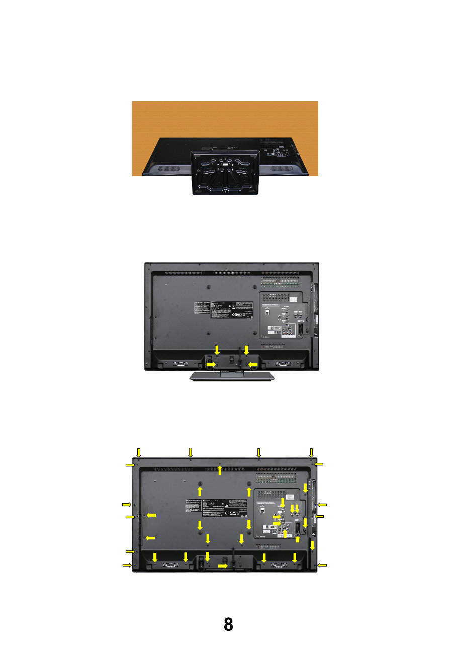
Service Hints
How to remove the backcover
Lay the main unit face down. (see Fig.5)
Remove the 4 fixing screws and the pedestal assembly. (see Fig.6)
Remove the 36[34] fixing screws, 4 caps and the backcover. (see Fig.7)
Fig.5
SCREWS
XYN4+F30FJK /4pcs/
Fig.6
Fig.7
SCREWS
(1) XTB4+15JFJK 19pcs[18]
(2) THEJ0389 15pcs[14]
(3) XTV3+10GFJK /2pcs/
(4) TKKL5521 /4pcs/
(1) (1) (1) (1)
(1) (1)
(1)
(1)
(1)
(1) (1)
(1)
(1)
(1)
(1)
(2)
(2)
(2)
(2) (2)
(2)
(2)
(2)
(2)
(2)
(3)
(3)
(2)
(1)
(1)
(1)
(2)
(4) (4)
(4) (4)
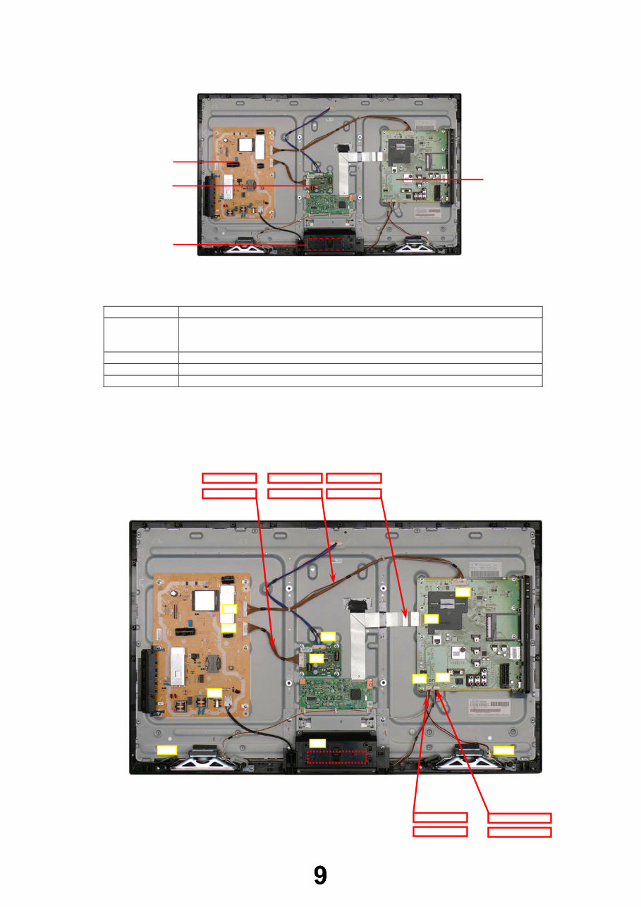
Chassis Board Layout
Location of Lead Wiring
To find the Part Number of required wire in Replacement Parts List click on the wire name in red box.
Board Name Function
A-Board AV Terminal, HDMI, USB, Digital Audio Out, TV tuner, SD Card, CI slot, PC,
Ethernet, Peaks_LDA3, AV Switch, HDMI Switch, Speaker out,
EEPROM, Flash Memory, DDR SDRAM
KA-Board Remote Receiver, Power and Timer LED, C.A.T.S
P-Board Main Input, Power Supply, Key control, Power switch
LD-Board LED driver
P-BOARD
KA-BOARD
A-BOARD
LD-BOARD
A02
SP_L
A10
A12
KA10
A15
SP_R
LD2
32“ A10-KA10 WIRE
32“ P4-LD4 WIRE
32“ A12-SPK WIRE
LD4
P1
P2
P4
32“ A02-P2 WIRE 32“ LVDS FFC
37“P4-LD4 WIRE 37“ A02-P2 WIRE 37“ LVDS FFC
37“ A10-KA10 WIRE 37“ A12-SPK WIRE
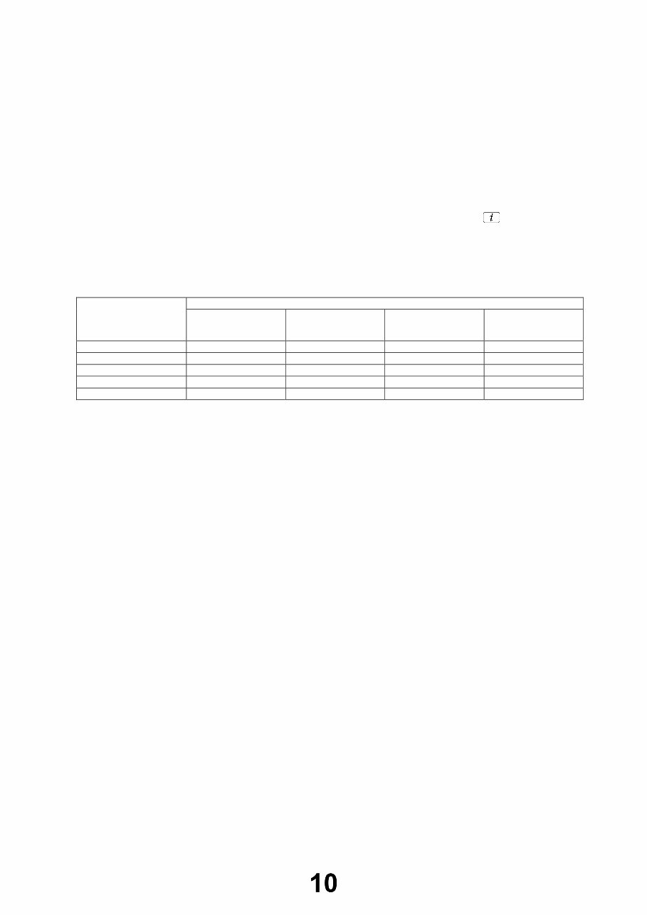
Technical Description
Specification of KEY for CI Plus, DTCP-IP, One-to-One and Widevine
General information:
1. EEPROM (IC8902) for spare parts has the seed of KEY for each.
2. The final KEY data will be generated by LDA3 IC (IC8000) when SELF CHECK was done and are stored in both LDA3 IC
(IC8000) and EEPROM (IC8902).
Three KEY are not generated for all models.
The necessary KEY are only generated and stored depend on the feature of models.
Replacement of ICs:
When LDA3 IC (IC8000) is replaced, EEPROM (IC8902) should be also replaced with new one the same time.
When EEPROM (IC8902) is replaced, LDA3 IC (IC8000) is not necessary to be replaced the same time.
After the replacement of IC, SELF CHECK should be done to generate the final KEY data.
How to SELF CHECK: While pressing [VOLUME ( - )] button on the main unit, press the STATUS button on the remote
control for more than 3 seconds.
TV will be forced to the factory shipment setting after this SELF CHECK.
Model and Keys:
Keys
Model No.
CI PLUS DTCP-IP
One-to-One
(for USB Rec.)
Widevine
TX-L32E30E Yes Yes Yes Yes
TX-LF32E30 Yes Yes Yes Yes
TX-LR32E30 None None None Yes
TX-L37E30E Yes Yes Yes Yes
TX-LF37E30 Yes Yes Yes Yes
You're Reading a Preview
What's Included?
Fast Download Speeds
Online & Offline Access
Access PDF Contents & Bookmarks
Full Search Facility
Print one or all pages of your manual
$31.99
$41.99
Viewed 43 Times Today


Secure transaction
What's Included?
Fast Download Speeds
Online & Offline Access
Access PDF Contents & Bookmarks
Full Search Facility
Print one or all pages of your manual
$31.99
$41.99
The Panasonic TX-L LCD Televisions OEM Service & Repair Manual is a comprehensive guide designed for repairing and maintaining the TX-L32E30E, TX-LF32E30, TX-LR32E30, TX-L37E30E, and TX-LF37E30 models with the LA18 Chassis. This digital manual, available in English, is compatible with both Windows and Mac platforms.
Whether you are a professional mechanic or a DIY enthusiast, this guide provides you with the essential technical information to troubleshoot and repair the listed Panasonic LCD TV models efficiently.
- Models Covered: TX-L32E30E, TX-LF32E30, TX-LR32E30, TX-L37E30E, TX-LF37E30
- Chassis: LA18
- Format: Digital Manual
- Platform Compatibility: Windows and Mac
- Language: English
- OEM Service & Repair Manual


