PLASMA TV
SERVICE MANUAL
CAUTION
BEFORE SERVICING THE CHASSIS,
READ THE SAFETY PRECAUTIONS IN THIS MANUAL.
CHASSIS : PU12A
MODEL : 50PZ950 50PZ950-UA
North/Latin America http://aic.lgservice.com
Europe/Africa http://eic.lgservice.com
Asia/Oceania http://biz.lgservice.com
Internal Use Only
Printed in Korea P/NO : MFL67006101(1101-REV00)
- 2 -
LGE Internal Use Only Copyright ©2011 LG Electronics Inc. All rights reserved.
Only for training and service purposes
CONTENTS
CONTENTS ............................................................................................................................... 2
SAFETY PRECAUTIONS ........................................................................................................... 3
SPECIFICATION ......................................................................................................................... 4
ADJUSTMENT INSTRUCTION .................................................................................................. 6
BLOCK DIAGRAM ................................................................................................................... 13
EXPLODED VIEW ................................................................................................................... 14
CIRCUIT DIAGRAM .....................................................................................................................
- 3 -
LGE Internal Use Only Copyright ©2011 LG Electronics Inc. All rights reserved.
Only for training and service purposes
SAFETY PRECAUTIONS
Many electrical and mechanical parts in this chassis have special safety-related characteristics. These parts are identified by in
the Schematic Diagram and Exploded View.
It is essential that these special safety parts should be replaced with the same components as recommended in this manual to
prevent X-RADIATION, Shock, Fire, or other Hazards.
Do not modify the original design without permission of manufacturer.
General Guidance
An isolation Transformer should always be used during the
servicing of a receiver whose chassis is not isolated from the AC
power line. Use a transformer of adequate power rating as this
protects the technician from accidents resulting in personal injury
from electrical shocks.
It will also protect the receiver and it's components from being
damaged by accidental shorts of the circuitry that may be
inadvertently introduced during the service operation.
If any fuse (or Fusible Resistor) in this monitor is blown, replace it
with the specified.
When replacing a high wattage resistor (Oxide Metal Film
Resistor, over 1W), keep the resistor 10mm away from PCB.
Keep wires away from high voltage or high temperature parts.
Due to high vacuum and large surface area of picture tube,
extreme care should be used in handling the Picture Tube.
Do not lift the Picture tube by it's Neck.
Leakage Current Cold Check(Antenna Cold Check)
With the instrument AC plug removed from AC source, connect
an electrical jumper across the two AC plug prongs. Place the
AC switch in the on position, connect one lead of ohm-meter to
the AC plug prongs tied together and touch other ohm-meter
lead in turn to each exposed metallic parts such as antenna
terminals, phone jacks, etc.
If the exposed metallic part has a return path to the chassis, the
measured resistance should be between 1MΩ and 5.2MΩ.
When the exposed metal has no return path to the chassis the
reading must be infinite.
An other abnormality exists that must be corrected before the
receiver is returned to the customer.
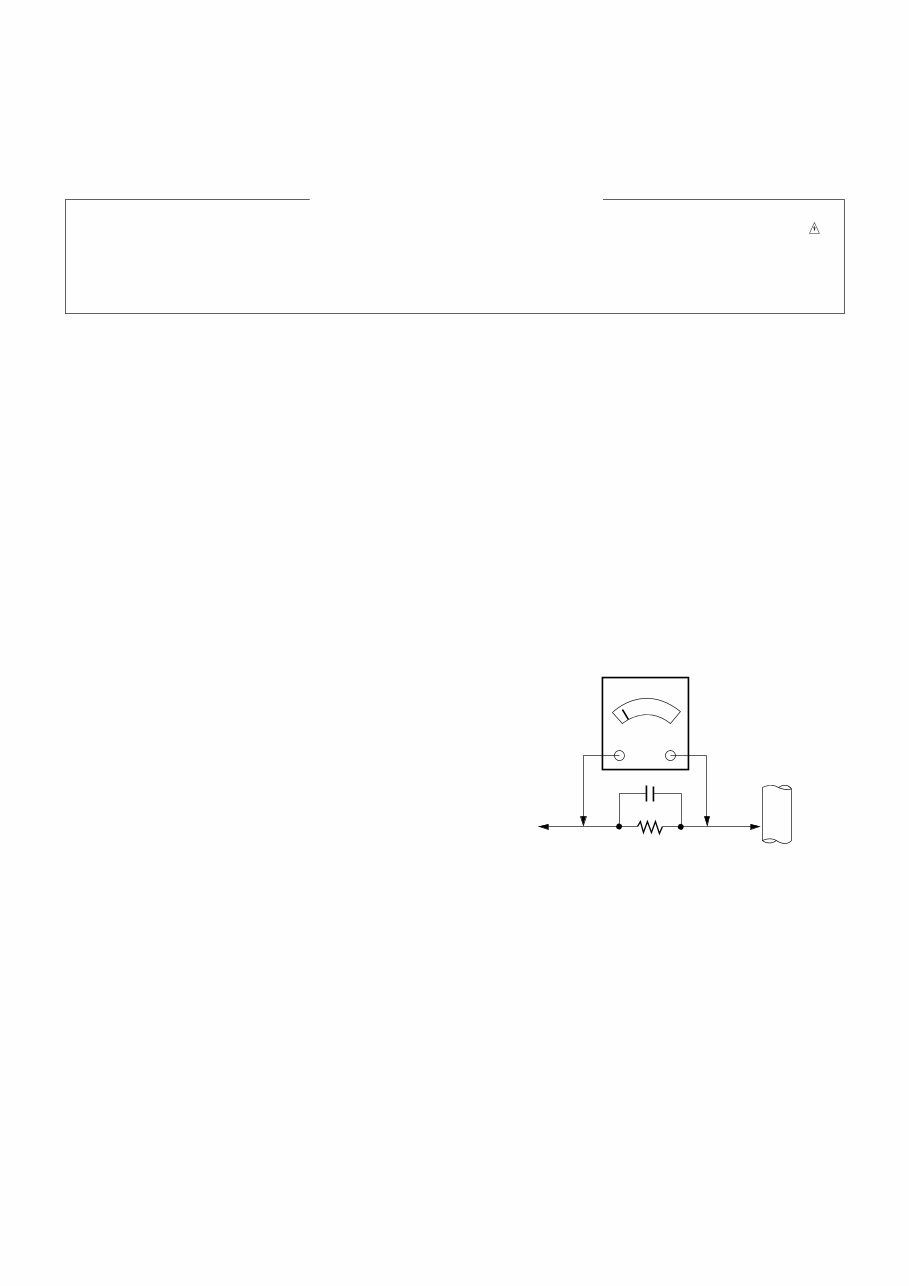
Leakage Current Hot Check (See below Figure)
Plug the AC cord directly into the AC outlet.
Do not use a line Isolation Transformer during this check.
Connect 1.5K/10watt resistor in parallel with a 0.15uF capacitor
between a known good earth ground (Water Pipe, Conduit, etc.)
and the exposed metallic parts.
Measure the AC voltage across the resistor using AC voltmeter
with 1000 ohms/volt or more sensitivity.
Reverse plug the AC cord into the AC outlet and repeat AC
voltage measurements for each exposed metallic part. Any
voltage measured must not exceed 0.75 volt RMS which is
corresponds to 0.5mA.
In case any measurement is out of the limits specified, there is
possibility of shock hazard and the set must be checked and
repaired before it is returned to the customer.
Leakage Current Hot Check circuit
1.5 Kohm/10W
To Instrument's
exposed
METALLIC PARTS
Good Earth Ground
such as WATER PIPE,
CONDUIT etc.
AC Volt-meter
IMPORTANT SAFETY NOTICE
0.15uF
- 4 -
LGE Internal Use Only Copyright ©2011 LG Electronics Inc. All rights reserved.
Only for training and service purposes
SPECIFICATIONS
NOTE : Specifications and others are subject to change without notice for improvement .
1. Application Range
(1) This spec sheet is applied all of PDP TV with PU12A chassis.
2. Specification
Each part is tested as below without special appointment.
(1) Temperature : 25 °C ± 5 °C (77 °F ± 9 °F), CST : 40 °C ± 5 °C
(2) Relative Humidity : 65 % ± 10 %
(3) Power Voltage : Standard input voltage (100 V - 240 V ~ 50 / 60 Hz)
* Standard Voltage of each product is marked by models
(4) Specification and performance of each parts are followed each drawing and specification by part number in accordance with
BOM.
(5) The receiver must be operated for about 5 minutes prior to the adjustment.
3. Test Method
(1) Performance : LGE TV test method followed.
(2) Demanded other specification
Safety : UL, CSA, IEC specification, CE
EMC : FCC, ICES, IEC specification, CE
Model Name
50PZ950-UA
Remark
Safety : UL1492, CSA C22.2.No.1
EMC : FCC Class B, IC Class B
Market
NORTH AMERICA
Model Name
50PZ950-UA
Brand
LG
Market
NORTH AMERICA
CANADA / MEXICO / PANAMA / COLOMBIA
- 5 -
LGE Internal Use Only Copyright ©2011 LG Electronics Inc. All rights reserved.
Only for training and service purposes
4. General Specification
No Item Specification Remark
1. Receiving System 1) ATSC / NTSC-M
2. Available Channel 1) VHF : 02~13
2) UHF : 14~69
3) DTV : 02~69
4) CATV : 01~135
5) CADTV : 01~135
3. Input Voltage 1) AC 100 V - 240 V ~ 50 / 60 Hz N.America Mark : 110V, 60Hz
4. Market NORTH AMERICA, KOREA
5. Screen Size 127 cm (50 inch) Wide(1920 × 1080) 50PZ950-UA, 50PZ950-UF
152 cm (60 inch) Wide(1920 × 1080) 60PZ950-UA, 60PZ950-UF
6. Aspect Ratio 16:9
7. Tuning System FS
8. PDP Module PDP50R3#### (1920 × 1080) 50PZ950-UA, 50PZ950-UF
PDP60R3#### (1920 × 1080) 60PZ950-UA, 60PZ950-UF
9. Operating Environment 1) Temp : 0 deg ~ 40 deg
2) Humidity : ~ 80 %
10. Storage Environment 1) Temp : -20 deg ~ 60 deg
2) Humidity : ~ 85 %
- 6 -
LGE Internal Use Only Copyright ©2011 LG Electronics Inc. All rights reserved.
Only for training and service purposes
ADJUSTMENT INSTRUCTION
1. Application Range
This spec. sheet applies to PU12A Chassis applied PDP TV
all models manufactured in TV factory.
2. Specification
(1) Because this is not a hot chassis, it is not necessary to use
an isolation transformer. However, the use of isolation
transformer will help protect test instrument.
(2) Adjustment must be done in the correct order.
(3) The adjustment must be performed in the circumstance of
25 c C ± 5 c C of temperature and 65 % ± 10 % of relative
humidity if there is no specific designation.
(4) The input voltage of the receiver must keep 100 V - 240 V,
50 / 60 Hz.
(5) The receiver must be operated for about 5 minutes prior to
the adjustment when module is in the circumstance of over
15 c C
- In case of keeping module is in the circumstance of 0 c C,
it should be placed in the circumstance of above 15 c C for
2 hours
- In case of keeping module is in the circumstance of below
-20 c C, it should be placed in the circumstance of above
15 c C for 3 hours.
Caution) When still image is displayed for a period of 20 minutes
or longer (especially where W/B scale is strong. Digital
pattern 13ch and/or Cross hatch pattern 09ch), there
can some afterimage in the black level area.
3. Adjustment items
3-1. Board-level adjustment
- Mac address and Idfile(ESN) Download
- Adjust 480i Comp1 adj.
- Adjust 1080p Comp1 adj.
- Adjust 1920*1080 RGB adj.
- EDID/DDC download
Above adjustment items can be also performed in Final
Assembly if needed. Both Board-level and Final assembly
adjustment items can be check using In-Start Menu 1.
Adjust Check.
3-2. Final assembly adjustment
- White Balance adjustment
- RS-232C functionality check
- Factory Option setting per destination
- Ship-out mode setting (In-Stop)
3-3. Etc.
- Ship-out mode
- Service Option Default
- USB Download(S/W Update, Option)
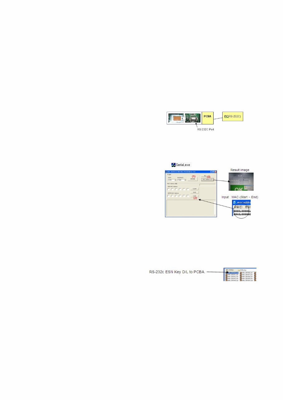
4. MAC Address and ESN Key Write
4-1. Equipment & Condition
- Play file: Serial.exe
- MAC Address edit
- Input Start / End MAC address
4-2. Download method
(1) Communication Prot connection
Connect: PCBA Jig-> RS-232C Port== PC-> RS-232C Port
(2) MAC Address Download
- Com 1,2,3,4 and 115200(Baudrate)
- Port connection button click(1)
- Load button click(2) for MAC Address write.
- Start MAC Address write button(3)
- Check the OK Or NG
(3) Input the ESN Key
(Except Mexico/Canada Models)
- download Model sending Key file
- input by 1 by SET so as not to be duplicated
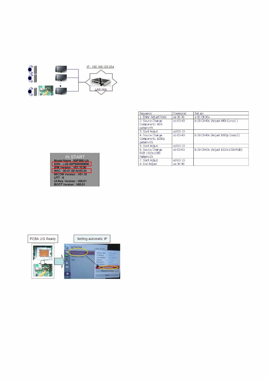
5. LAN PORT + ESN INSPECTION
5-1. Equipment & Condition
- Each other connection to LAN Port of IP Hub and Jig
5-2. MAC Address & ESN Key & widevine
Key confirmation
MAC Address & ESN Key & widevine Key confirmation
MAC Address : All Models
widevine Key : All Models
ESN Key D/L : Except Mexico/Canada Models
- Push “IN-START” Key in service remote controller.
5-3. LAN PORT INSPECTION(PING TEST)
- LAN Port connection with PCB
- Network setting at MENU Mode of TV
- setting automatic IP
- Setting state confirmation
-> If automatic setting is finished, you confirm IP and MAC
Address.
- remove LAN CABLE
6. ADC adjustment
6-1. Overview
ADC adjustment is needed to find the optimum black level and
gain in Analog-to-Digital device and to compensate RGB
deviation.
6-2. Equipment & Condition
(1) Jig (RS-232C protocol)
(2). Internal pattern is used. No external signal is needed.
6-3. Adjustment
(1) Adj. protocol
(2) Check adjust device
Pattern Generator : (MSPG-925FA)
Adjust 480i Comp1
(MSPG-925FA:model :209 , pattern :65)
Adjust 1080p Comp1
(MSPG-925FA:model :225 , pattern :65)
Adjust RGB (MSPG-925FA:model :225 , pattern :65)
The PU02A have not ECHO.
7. EDID(The Extended Display
Identification Data) / DDC(Display
Data Channel) download
7-1. Overview
It is a VESA regulation. A PC or a MNT will display an optimal
resolution through information sharing without any necessity
of user input. It is a realization of °∞Plug and Play°±.
7-2. Equipment
- Adj. R/C
- Since embedded EDID data is used, EDID download jig,
HDMI cable and D-sub cable are not need.
7-3. Download method
(1) Press Adj. key On the Adj. R/C, press Adj. key then select
EDID D/L. By pressing Enter key, EDID download will
begin.
(2) If Download is successful, OK is displayed.
(3) If Download is a failure, NG is displayed.
(4) Re-try download
- 7 -
LGE Internal Use Only Copyright ©2011 LG Electronics Inc. All rights reserved.
Only for training and service purposes
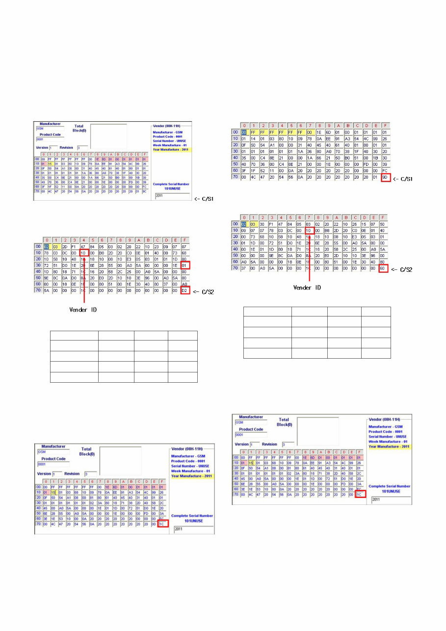
7-4. EDID DATA(PCM)
- Reference: Download is only possible in POWER ON
MODE.
- HDMI
EDID Block 0, Bytes 0-127 [00H-7FH]
Block Type : EDID 1.4
EDID Block 1, Bytes 128-255 [80H-FFH]
Block Type: CEA EDID Timing Extension Version 3
RGB [C/S: 1C]
EDID Block 0, Bytes 0-127 [00H-7FH]
Block Type: EDID 1.3
7-5. EDID DATA(AC-3)
- Reference: Download is only possible in POWER ON
MODE.
- HDMI
EDID Block 0, Bytes 0-127 [00H-7FH]
Block Type : EDID 1.4
EDID Block 1, Bytes 128-255 [80H-FFH]
Block Type: CEA EDID Timing Extension Version 3
RGB [C/S: 1C]
EDID Block 0, Bytes 0-127 [00H-7FH]
Block Type: EDID 1.3
- 8 -
LGE Internal Use Only Copyright ©2011 LG Electronics Inc. All rights reserved.
Only for training and service purposes
Vender ID C/S1 C/S2
HDMI1 10 9C D2
HDMI2 20 9C C2
HDMI3 30 9C B2
HDMI4 40 9C A2
Vender ID C/S1 C/S2
HDMI1 10 9C 60
HDMI2 20 9C 50
HDMI3 30 9C 40
HDMI4 40 9C 30
8. White Balance adj.
8-1. Overview
(1) W/B adj.: Objective & How-it-works
1) Objective: To reduce each Panel’s W/B deviation
2) How-it-works: When R/G/B gain in the OSD is at 192, it
means the panel is at its Full Dynamic
Range. In order to prevent saturation of
Full Dynamic range and data, one of
R/G/B is fixed at 192, and the other two is
lowered to find the desired value.
8-2. Equipment
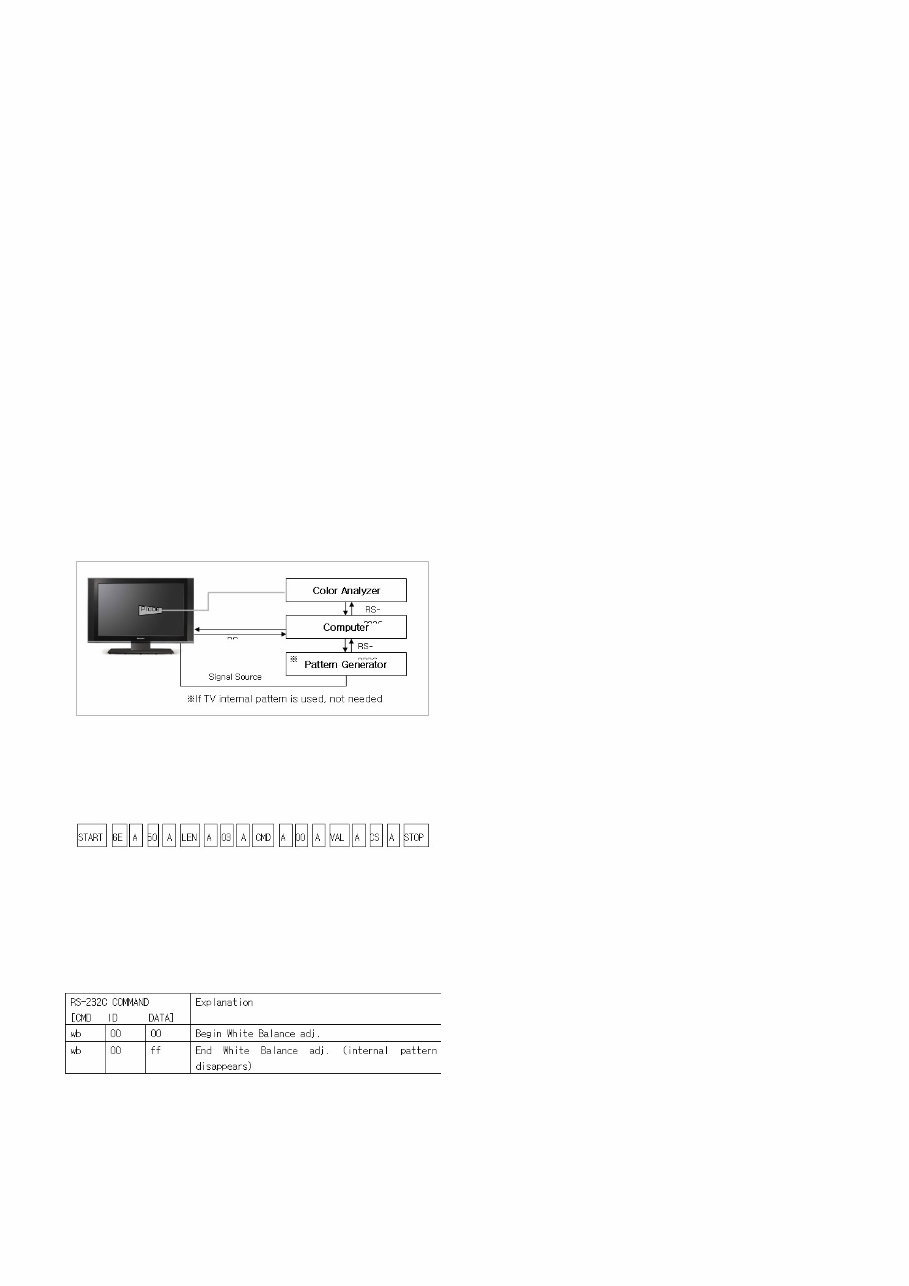
(1) Color Analyzer : CA-210 (NCG: CH 9 / WCG: CH12 /PDP
Module:CH10)
(2) Adj. Computer
(During auto adj., RS-232C protocol is needed)
(3) Adj. R/C
(4) Video Signal Generator MSPG-925F 720p/216Gray
(Model:217, Pattern:78)
-> Only when internal pattern is not available
- Color Analyzer Matrix should be calibrated using CS-1000
8-3. Equipment connection map
8-4. Adj. Command (Protocol)
O Protocol
<Command Format>
- LEN: Number of Data Byte to be send
- CMD: Command
- VAL: FOS Data
- CS: Checksum of sent Data
- A: Acknowledge
Ex) [Send: JA_00_DD] / [Ack: A_00_okDDX]
O RS-232C Command used during auto-adj.
Ex) wb 00 00 -> Begin white balance auto-adj.
wb 00 10 -> Gain adj.
ja 00 ff -> Adj. data
jb 00 c0
...
...
wb 00 1f -> Gain adj. complete
*(wb 00 20(Start), wb 00 2f(End)) -> Off-set adj.
wb 00 ff -> End white balance auto-adj.
8-5. Auto Adj. method
(1) Set TV in adj. mode using POWER On Key
(2) Zero calibrate probe then place it on the center of the
Display
(3) Connect Cable(RS-232C)
(4) Select mode in adj. Program and begin adj.
(5) When adj. is complete (OK Sign), check adj. status per
mode
(Warm, Medium, Cool)
(6) Remove probe and RS-232C cable to complete adj.
- Adj. must begin w/ command “wb 00 00”, and end “wb 00
ff” and adj. offset if needed.
- Offset adjust limit value.
Offset Min = 34 (Decimal)
Offset Max = 94 (Decimal)
8-6. Manual adj. method
Dynamic contrast : off
Dynamic color : off
OPC : Off
Energy saving mode : Off
(1) Set TV Picture Mode to Standard and in Advanced
Control, set Dynamic Contrast and Color ‘ Off ’ .
(2) Set TV in adj. mode using POWER On Key
(3) Press ADJ key -> EZ adjust using adj. R/C
(4) Using CH + / - KEY, select 10.TEST PATTERN then press
Enter to place in HEAT RUN mode and wait for 30
minutes.
(4) Zero calibrate the probe of Color Analyzer, then place it on
the center of LCD module within 10 cm of the surface.
(5) Press ADJ key -> 7. White-Balance then press the cursor
to the right (KEY G )
(When G is pressed Full White internal pattern will be
displayed)
(6) One of R Gain / G Gain / B Gain should be fixed at 192,
and the rest will be lowered to meet the desired value.
(7) Adj. is performed in COOL, MEDIUM, WARM 3 modes of
color temperature
(8) Offset Adjust in MEDIUM, WARM 2 modes of color
temperature ( Only THX Model )
V If internal pattern is not available, use HDMI input. In EZ
Adj. menu 7.White Balance, you can select one of 3
options: None, Inner, HDMI. Default is inner. By selecting
HDMI, you can adjust using HDMI signal.
- 9 -
LGE Internal Use Only Copyright ©2011 LG Electronics Inc. All rights reserved.
Only for training and service purposes
V Adj. condition and cautionary items
(1) Lighting condition in surrounding area
Surrounding lighting should be lower than 10 lux. Try
to isolate adj. area into dark surrounding.
(2) Probe location
- PDP : Color Analyzer (CA-100, CA-100+, CA210)
probe should be firmly attached to the Module
- LCD : Color Analyzer (CA-210) probe should be within
10cm and perpendicular of the module surface
(80°~ 100°)
- In case of LCD, B/L on should be checked using no
signal or Full white Pattern
8-7. Reference (White Balance adj.
coordinate and color temperature)
O Standard color coordinate and temperature using CS-1000
O Luminance: Full white 216 Gray
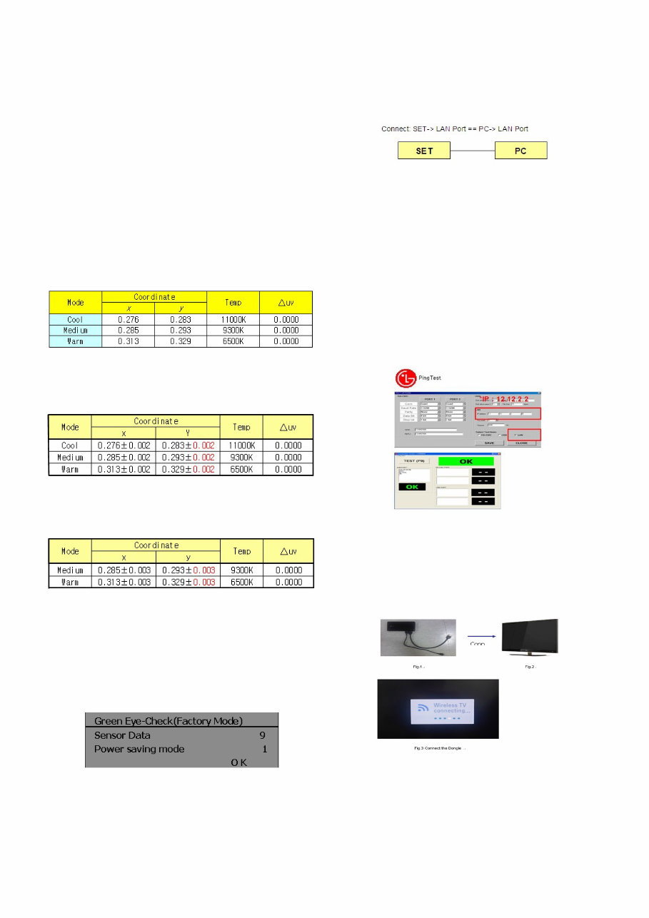
O Standard color coordinate and temperature using CA-210(CH
10)
- Gain color coordinate
O Pattern : Full white 216 Gray
- Offset color coordinate : Only THX model
O Pattern : Full white 50 Gray
O Luminance : 5 ± 4 cd
9. Checking the EYE-Q Operation.
(1) Press the EYE Key on the adjustment remote controller.
(2) Check the Sensor DATA ( It must be under 10) and keep
the data longer than 1.5s
(3) Check ‘OK’
(Sensor DATA 0 ~ 4095, Power Saving Mode 0 ~ 12)
* IF you press IN-STAP Button, change Green Eye-check OSD.
10. Ping TEST
* This test is to check Network operation.
10-1. Equipment Setting
(1) Play the LAN Port Test PROGRAM.
(2) Input IP set up for an inspection to Test
*IP Number : 12.12.2.2
11. LAN PORT inspection
(PING TEST)
* In this case Network setting is on Manual Setting.
(1) Play the LAN Port Test Program.
(2) connect each other LAN Port Jack.
(3) Play Test (F9) button and confirm OK Message.
(4) remove LAN CABLE
12. Check Wireless function .
(1) Connect set and Dongle of Wireless to Cable of HDMI &
TTA 20Pin
(2) At OSD of SET, check the message like Fig 3.
(3) Detach Cable of Wireless Dongle
- 10 -
LGE Internal Use Only Copyright ©2011 LG Electronics Inc. All rights reserved.
Only for training and service purposes
You're Reading a Preview
What's Included?
Lifetime Access
Access PDF Contents & Bookmarks
Print one or all pages of your manual



 Lifetime Access




