

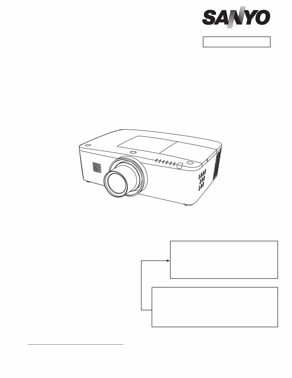
Multimedia Projector
SERVICE MANUAL
Original Version
REFERENCE NO. SM5111255-00
FILE NO.
Model No. PLC-WM5500L
PLC-WM5500
U.S.A, Canada,
Europe, U.K, Asia
Brazil
PLC-WM5500L
* Projection lens is optional.
Chassis No. KK8-WM5500L00
KK8-WM550000
Match the Chassis No. on the rating label of the projector
with the Chassis No. in the Service Manual.
If the Original Version Service Manual Chassis No. does
not match, additional Service Literature is required. You
must refer to “Notices” to the Original Service Manual prior
to servicing.
PLC-WM5500 PLC-WM5500L
1 122 515 00 (KK8A) 1 122 515 20 (KK8AL)
1 122 515 04 (KK8E) 1 122 515 24 (KK8EL)
1 122 516 00 (LK8A) 1 122 516 20 (LK8AL)
1 122 516 02 (LK8C) 1 122 516 22 (LK8CL)
1 122 516 03 (LK8D) 1 122 516 23 (LK8DL)

-2-
Contents
SERVICE MANUAL ....................................................... 1
Contents ........................................................................ 2
Safety Instructions ......................................................... 3
Safety Precautions ..................................................... 3
Product Safety Notice................................................. 3
Service Personnel Warning ........................................ 3
Specifications ................................................................ 4
Circuit Protections ......................................................... 5
Fuse ............................................................................ 5
Thermal protectors (SW902) ...................................... 5
Mechanical sensor switches (SW901, SW1891) ......... 6
Temperature sensors, wind sensors........................... 7
Power failure and fan lock detection........................... 8
Maintenance .................................................................. 9
Replacing the Filter Cartridge..................................... 9
Lamp Replacement ...................................................11
How to check Lamp Used Time ............................... 12
Quick maintenance ................................................... 13
Lens Installation........................................................ 14
Using the Lens Antitheft screw ................................. 15
Cleaning ................................................................... 16
Cleaning the Projection Lens ................................... 16
Cleaning the Projector Cabinet................................. 16
Security Function Notice ............................................. 17
Mechanical Disassembly............................................. 18
Optical Parts Disassembly .......................................... 27
Adjustments................................................................. 33
Adjustments after Parts Replacement ...................... 33
Note on Main Board Replacement ........................... 33
Service Adjustment Menu Operation ....................... 34
Optical Adjustment ...................................................... 35
1. Optical axis adjustment ........................................ 36
2. Contrast adjustment ............................................. 40
Electrical Adjustments ................................................. 41
Circuit Adjustments................................................... 41
Test Points and Locations ........................................ 45
Service Adjustment Data Table ................................ 46
Troubleshooting ........................................................... 65
Chassis over view ..................................................... 65
No Power .................................................................. 66
No Power (Power supply) ......................................... 67
No Power (Power supply) ......................................... 68
No Power (Fan control)............................................. 69
No Power (Lamp control) .......................................... 70
Temperature Abnormality ......................................... 71
No Picture ................................................................. 72
No Sound.................................................................. 73
Motor control problems ............................................. 74
Bus control................................................................ 75
LED drive & RC control ........................................... 76
Indicators and Projector Condition ........................... 77
Power failure detection system ................................ 80
Diagnosis of Power Failure with RS-232C port ........ 84
Serial Control Interface............................................. 85
Control Port Functions................................................. 87
IC Block Diagrams....................................................... 90
Parts Location Diagrams ........................................... 100
Mechanical Parts List ................................................ 109
Electrical Parts List ..................................................... 111
Diagrams & Drawings.................................................. A1
Parts description and reading in schematic diagram ..A2
Schematic Diagrams ................................................... A3
Printed Wiring Board Diagrams ................................. A13
Pin description of diode, transistor and IC................. A17
Note on Soldering...................................................... A18

-3-
Safety Instructions
WARNING:
The chassis of this projector is isolated (COLD) from AC line by using the converter transformer. Primary side
of the converter and lamp power supply unit circuit is connected to the AC line and it is hot, which hot circuit is
identified with the line ( ) in the schematic diagram. For continued product safety and protection of per-
sonnel injury, servicing should be made with qualified personnel.
The following precautions must be observed.
Safety Precautions
1: An isolation transformer should be connected in
the power line between the projector and the AC
line before any service is performed on the projec-
tor.
2: Comply with all caution and safety-related notes
provided on the cabinet back, cabinet bottom, inside
the cabinet or on the chassis.
3: When replacing a chassis in the cabinet, always
be certain that all the protective devices are
installed properly, such as, control knobs, adjust-
ment covers or shields, barriers, etc.
DO NOT OPERATE THIS PROJECTOR WITHOUT
THE PROTECTIVE SHIELD IN POSITION AND PR
OPERLY SECURED.
4: Before replacing the cabinet cover, thoroughly
inspect the inside of the cabinet to see that no stray
parts or tools have been left inside.
Before returning any projector to the customer, the
service personnel must be sure it is completely safe
to operate without danger of electric shock.
Service Personnel Warning
Eye damage may result from directly viewing the light produced by the Lamp used in this equipment. Always
turn off Lamp before opening cover. The Ultraviolet radiation eye protection required during this servicing.
Never turn the power on without the lamp to avoid electric-shock or damage of the devices since the stabilizer
generates high voltages (15kV - 25kV) at its starts.
Since the lamp is very high temperature during units operation replacement of the lamp should be done at least
45 minutes after the power has been turned off, to allow the lamp cool-off.
Product Safety Notice
Product safety should be considered when a component replacement is made in any area of the projector.
Components indicated by mark ! in the parts list and the schematic diagram designate components in which
safety can be of special significance. It is, therefore, particularly recommended that the replacement of there
parts must be made by exactly the same parts.

-4-
Specifications
This symbol on the nameplate means the product is Listed by Underwriters
Laboratories Inc. It is designed and manufactured to meet rigid U.L. safety stan-
dards against risk of fire, casualty and electrical hazards.
● The specifications are subject to change without notice.
● LCD panels are manufactured to the highest possible standards. Even though 99.99% of the pixels are effective, a tiny
fraction of the pixels (0.01% or less) may be ineffective by the characteristics of the LCD panels.
Mechanical Information
Projector Type Multi-media Projector
Dimensions (W x H x D) PLC-WM5500L : 19.25” x 6.46” x 14.61” (489.5 mm x 164.0 mm x 371.1 mm)
PLC-WM5500 : 19.25” x 6.46” x 17.12” (489.5 mm x 164.0 mm x 434.8 mm)
Net Weight PLC-WM5500L : 19.6 lbs (8.9kg)
PLC-WM5500 : 21.3 lbs (9.7 kg)
Feet Adjustment 0˚ to 4˚
Panel Resolution
LCD Panel System 0.75” TFT Active Matrix type, 3 panels
Panel Resolution 1,280 x 800 dots
Number of Pixels 3,072,000 (1,280 x 800 x 3 panels)
Signal Compatibility
Color System PAL, SECAM, NTSC, NTSC4.43, PAL-M, and PAL-N
SD/HD TV Signal 480i, 480p, 575i, 575p, 720p, 1035i, 1080i and 1080p
Input Scanning Frequency H-sync. 15 kHz–100 kHz, V-sync. 48 Hz–100 Hz
Optical Information
Projection Image Size (Diagonal) Adjustable from 40” to 400” (PLC-WM5500)
Throw Distance 4.5' (1.4m) - 80.1' (24.4m) (PLC-WM5500)
Projection Lens F1.7–2.3 lens with f=26.9 mm–45.4 mm with motor zoom and focus
(PLC-WM5500)
Projection Lamp 330 W NSHA lamp
Interface
Input 1 HDMI/D-sub15pin(RGB, RGB Scart)
Input 2 BNC Type x 5 (G or Video/Y, B or Pb-Cb, R or Pr-Cr, H/HV and V)
Input 3 RCA Type x 3 (Video/Y, Pb/Cb,Pr/Cr), Mini DIN 4 pin x 1 (S-video)
Analog Out Analog RGB (Mini D-sub 15 pin) Terminal x 1
Audio Out Audio (Mini Type stereo) x 1 (Variable)
Audio In 1/2 Audio (Mini Type stereo) x 1
Audio In 3 RCA Type x 2
R/C Jack Mini jack (Wired Remote) x 1
Control Port D-sub 9 pin x 1
USB Connector USB Series B x 1
Option PJ-Net Organizer Terminal x 1
LAN Connection Terminal RJ45
Audio
Internal Audio Amp 7.0 W RMS
Built-in Speaker 1 speaker, ø1.46" (37mm)
Power
Voltage and Power Consumption AC 100–120 V (5.2A Max. Ampere), 50/60 Hz (The U.S.A and Canada)
AC 100-240 V (5.2-2.5A Max. Ampere), 50/60Hz (For other countries)
Operating Environment
Operating Temperature 41˚F–104˚F (5˚C–40˚C)
Storage Temperature 14˚F–140˚F (-10˚C–60˚C)
Remote Control
Battery AAA or LR03 Type x 2
Operating Range 16.4’ (5 m/±30˚)
Dimensions 1.8” (W) x 1.0” (H) x 5.7” (D) (45 mm x 25 mm x 145 mm)
Net Weight 3.5 oz (99 g) (including batteries)
Accessories
Owner’s Manual (CD-ROM) Lens Cap (for PLC-WM5500)
Quick Reference Guide Lens Mount Cover (for PLC-WM5500L)
AC Power Cord Lens Antitheft screw *
Remote Control and Batteries VGA Cable
PIN Code Label
-5-
This projector provides the following circuit protections to operate in safety. If the abnormality occurs inside the pro-
jector, it will automatically turn off by operating one of the following protection circuits.
Circuit Protections
Fuse
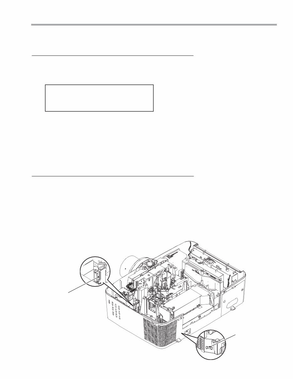
A fuse is located inside of the projector. When the POWER indicator is not
lighting, the fuse may be opened. Check the fuse as following steps.
The fuse should be used with the following type;
Fuse Part No. : 323 027 2605
TYPE T10AH 250V
LITTEL FUSE INC. TYPE 215010
How to replace the fuse
1. The fuse is placed on the power board under the main board. Remove the
cabinet top and exhaust fan assy.
2. Remove the fuse from fuse holder on the power board.
Thermal protector
(SW902)
Thermal protectors (SW902)
There are the thermal protector (SW902) inside of the projector to detect
the lamp surrounding temperature rising abnormally. When the temperature
reaches near 115˚C, the thermal protector cuts off the current supplied to the
power supply circuit.
To reset the thermal protection function, disconnect the AC cord and leave
the projector at the normal surrounding temperature for about 45 minutes.
The thermal protectors will automatically reset when the internal temperature
becomes normal (less than 75˚C) .
F601
Fuse
-6-
Circuit Protections
Mechanical sensor switches (SW901, SW1891)
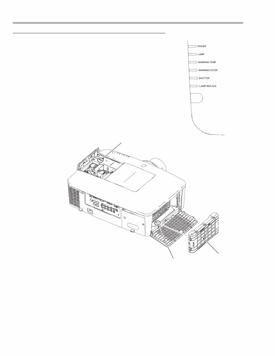
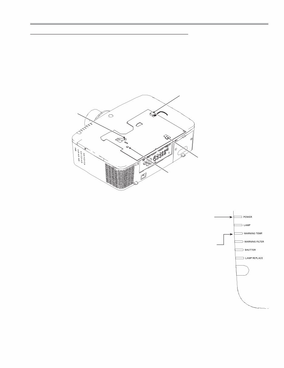
This projector provides 2 mechanical sensor switches, the one is for filter car-
tridge switch (SW1891) and the other one is for lamp cover switch (SW901).
The filter cartridge switch detects whether the filter cartridge is installed cor-
rectly. If the filter cartridge is not installed correctly, the projector cannot turn
on. In this case, the LAMP indicator is lighting and other indicators are blink-
ing.
The lamp cover switch detects whether the lamp cover is closed securely. If
lamp cover is opened or not closed completely, the drive signal to the lamp cir-
cuit is cut off. After opening the lamp cover for replacing the lamp ass’y, place
the lamp cover correctly otherwise the projector cannot turn on. In this case,
the LAMP indicator is lighting and LAMP REPLACE indicator is blinking.
Filter cartridge switch
(SW1891)
Lamp cover switch
(SW901)
Filter cartridge
LED indicators
-7-
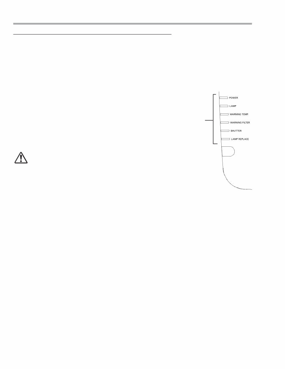
The projector provides 2 temperature sensor ICs, 1 thermistor, and 1 wind sensor on the intake duct. These devices
are monitoring the surrounding temperature of the lamp, panel and intake duct, and the wind sensor is monitoring
airflow passed through the air filter in the intake duct.
- Internal temperature sensor A (IC1692) (around the Intake duct)
- Internal temperature sensor B (IC1816) (around the lamp house)
- Internal temperature sensor C (IC1814) (around the panel/prism)
- Wind sensor D (S901) (intake duct)
Circuit Protections
IC1814 on the
Sensor C Board
IC1692 on the
Sensor A Board
The projector is shut down and the WARNING TEMP. indicator
is blinking red.
When the temperature inside the projector reaches a certain level,
the WARNING TEMP. indicator starts blinking. If the temperature
rises moreover, the projector will be automatically shut down to pro-
tect the inside of the projector, and the WARNING TEMP indicator is
blinking fast and the POWER indicator is blinking. When the projec-
tor has cooled down enough (to its normal operating temperature),
the POWER indicator stops blinking and it can be turned on again
by pressing the ON/STAND-BY button.
✔Note:
• The WARNING TEMP. indicator continues to blink even after the
temperature inside the projector returns to normal. When the projec-
tor is turned on again, the WARNING TEMP. indicator stops blinking.
POWER indicator
LED indicators
Temperature sensors, wind sensors
IC1816 on the Main
Board (behind)
S901
Wind Sensor
WARNING TEMP.
indicator
Then check the matters below:
– Did you provide appropriate space for the projector to be ventilated?
Check the installing condition to see if the air vents of the projector
are not blocked.
– Has the projector been installed near an Air-Conditioning/ Heating
Duct or Vent? Move the installation of the projector away from the
duct or vent.
– Is the filter clean? Replace the filter with a new one.
-8-
The projector provides the detection circuits of the power failure and the fan lock. When the detection circuit detects
an error at the power supply line or at the fan operation circuit, the projector will turn into the standby mode to protect
the other circuits defective.
Circuit Protections
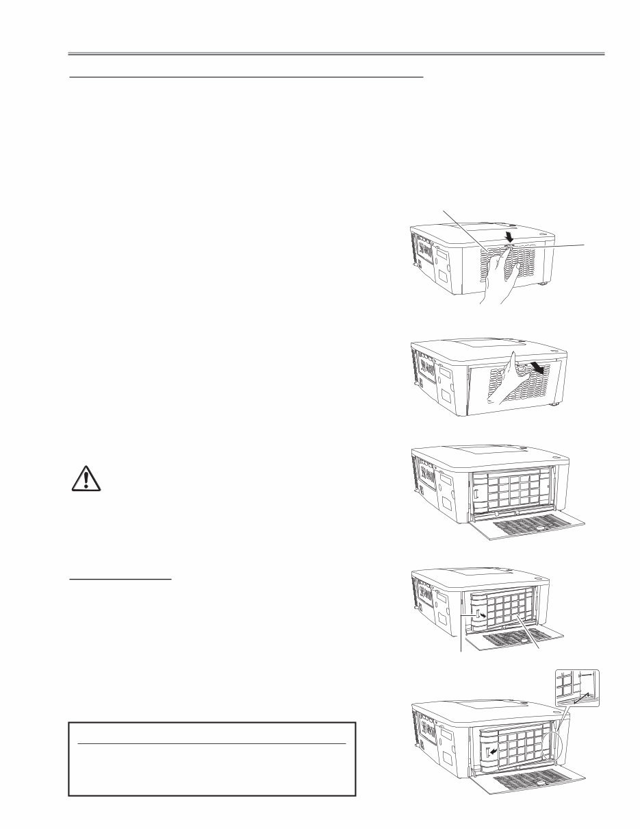
The projector is shut down and the LAMP indicator is
lighting and other indicators are blinking.
When the projector detects an abnormal condition, it will be
automatically shut down to protect the inside of the projector
and the LAMP indicator lights on and other indicators blink
In this case, unplug the AC power cord and plug it, and then
turn on the projector once again to verify operation. If the
projector cannot be turned on and these indicators still light-
ing and blinking, it may operate the power failure protection
function.
Check that the filter cartridge is installed correctly.
CAUTION
DO NOT LEAVE THE PROJECTOR WITH THE
AC POWER CORD CONNECTED UNDER AN AB-
NORMAL CONDITION. IT MAY RESULT IN FIRE
OR ELECTRIC SHOCK.
Power failure and fan lock detection
LED indicators
LAMP indicator lights on
and other indicators
blink.
-9-
Maintenance
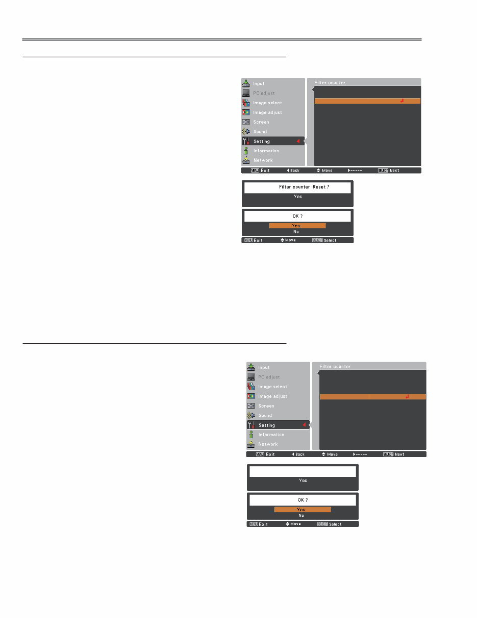
Turn off the projector, and unplug the AC power cord
from the AC outlet.
First, clean up the dust on the projector and around the
air vents.
1
2
Press d downwards on the filter cover to release the
latch and open the filter cover.
3
Put the new one back into the position and close the
filter cover. Make sure that the filter cartridge is properly
and fully inserted.
5
CAUTION
Make sure the filter cartridge is inserted in the
projector. If the filter cartridge is not inserted, the
projector cannot be turned on. Make sure the filter
cover is closed when using the projector.
Do not put anything into the air vents. Doing so may
result in malfunction of the projector.
4
Reset the filter counter and the scroll counter . See
next page.
6
Replacing the Filter Cartridge
Pull out the filter cartridge. When taking out the filter
cartridge, put your finger on the filter cartridge’s tab and
then pull.
RECOMMENDATION
We recommend avoiding dusty/smoky environments
when operating the projector. Usage in these environ-
ments may cause a poor image quality.
When using the projector under dusty or smoky conditions,
dust may accumulate on a lens, liquid crystal panels, or op-
tical elements inside the projector. Such condition may de-
grade the quality of the projected image.
When the symptoms above are noticed, contact your autho-
rized dealer or service station for proper cleaning.
ORDER REPLACEMENT FILTER CARTRIDGE
Type No. POA-FIL-080
Service Parts No.: 610 346 9034
Connect the AC power cord to the projector and turn
on the projector.
7
Filter prevents dust from accumulating on the optical elements inside the projector. Should the filter becomes clogged
with dust particles, it will reduce cooling fans’ effectiveness and may result in internal heat buildup and adversely af-
fect the life of the projector. This projector has an electrically operated filter which helps you to replace the filter easily.
The projector monitors the condition of the filter at all time and replaces a filter with a new one automatically when it
detects the clogging.
If the projector detects that the filter is clogged and no scroll is left in the filter cartridge, a Filter cartridge replacement
icon appears on the screen and the WARNING FILTER indicator on the top panel lights up. When you see this icon,
replace the filter cartridge and reset the Filter counter and the Scroll counter.
Filter cover
Latch
Filter cartridge
Tab
-10-
Resetting the Scroll Counter
Scroll counter
Resetting the Filter Counter
Filter counter
Be sure to reset the Filter counter after replacing the filter car-
tridge.
Press the MENU button to display the On-Screen Menu.
Use the Point ed buttons to select Setting and then
press the Point 8 or the SELECT button
Use the Point ed buttons to select Filter counter and
then press the SELECT button. Use the Point ed but-
tons to select Filter counter Reset and press the SE-
LECT button. Filter counter Reset? appears. Select
[Yes] to continue.
1
2
Another confirmation dialog box appears, select [Yes] to
reset the Filter counter.
3
Be sure to reset the Scroll counter after replacing the filter
cartridge.
Press the MENU button to display the On-Screen Menu.
Use the Point ed buttons to select Setting and then
press the Point 8 or the SELECT button
Use the Point ed buttons to select Filter counter and
then press the SELECT button. Use the Point ed but-
tons to select Scroll counter Reset and press the SE-
LECT button. Scroll counter Reset? appears. Select
[Yes] to continue.
1
2
Another confirmation dialog box appears, select [Yes] to
reset the Scroll counter.
3
Maintenance
Filter counter
Reset? appears.
Select Yes, then
another confirmation
box appears.
Select Yes again to
reset the Filter coun-
ter.
Filter counter 150 H
Timer 400 H
Filter counter reset
Scrolls remaining 9 Scroll(s)
Scroll counter Reset
Scroll counter
Reset? appears.
Select Yes, then
another confirmation
box appears.
Select Yes again
to reset the Scroll
counter.
Scroll counter Reset?
Filter counter 150 H
Timer 400 H
Filter counter reset
Scrolls remaining 9 Scroll(s)
Scroll counter Reset
You're Reading a Preview
What's Included?
 Lifetime Access
Fast Download Speeds
Online & Offline Access
Access PDF Contents & Bookmarks
Full Search Facility
Print one or all pages of your manual
$36.99
Sanyo PLC-WM5500L Multimedia Projector Service Manual
Viewed 95 Times Today

What's Included?
Lifetime Access
Fast Download Speeds
Online & Offline Access
Access PDF Contents & Bookmarks
Full Search Facility
Print one or all pages of your manual
$36.99

Secure transaction
What's Included?
Lifetime Access
Fast Download Speeds
Online & Offline Access
Access PDF Contents & Bookmarks
Full Search Facility
Print one or all pages of your manual
Description
The Sanyo PLC-WM5500L Multimedia Projector Service Manual is an essential resource for anyone involved in the repair and maintenance of the PLC-WM5500 model. This comprehensive manual provides detailed insights into the specifications, safety protections, and various procedures related to the projector's components.
- Air filter replacement and lamp replacement instructions are included, along with guidance on resetting the lamp or filter timer.
- Mechanical and optical disassembly procedures, as well as LCD panel replacement instructions, are provided to facilitate effective repairs.
- The manual also covers adjustments, including optical and electrical adjustments, to ensure optimal projector performance.
- Furthermore, the chassis description and troubleshooting section, along with control port functions, offer valuable insights for both professional mechanics and DIY enthusiasts.
- Additionally, the manual contains cleaning instructions, IC block diagrams, electrical and mechanical parts lists, as well as diagrams, drawings, and schematic diagrams for comprehensive understanding.
- Pin descriptions of diodes, transistors, and ICs, along with detailed specifications, further enhance the manual's utility.
This 168-page manual is available in English and is compatible with both Windows and MAC platforms, making it accessible to a wide range of users involved in projector maintenance and repair.


