

Panasonic PT DZ770 Service Manual and Repair Guide
What's Included?
Fast Download Speeds
Online & Offline Access
Access PDF Contents & Bookmarks
Full Search Facility
Print one or all pages of your manual

ORDER NO. VED1206435CE
D10
■
Replacement lamp unit
ET-LAD60A (1 bulb)
ET-LAD60AW (2 bulbs)
■
Replacement filter unit
ET-EMF300
■ This manual is common to all the models regardless of suffixes of the Model No.
・S: Silver model, the standard zoom lens supplied ・LS: Silver model, the lens sold separately
・K: Black model, the standard zoom lens supplied ・LK: Black model, the lens sold separately
■ Points of difference between the DZ6700
・Equipped with HDMI input terminal.
・Brightness 6,000 im ⇒ 7,000 lm.
・New Liquid Cooling System. (Same as DW730/DX800)
・Eco-Filter. (Common use of DW730/DX800)
・Add items in "PICTURE MODE". (DICOM Simulation/Rec.709)
・Add "CHEDULE" function.
・"CUT OFF" function. (Service mode ⇒ User mode)
・Crestron RoomView™ and AMX Device function corresponding.
© Panasonic Corporation 2012. Unauthorized
copying and distribution is a violation of law.
Model No.
1-chip DLP Based Projector
PT-DZ770U
PT-DZ770E
PT-DZ770UL
PT-DZ770EL
The service technician is required to read and follow the “Safety Precautions” and “Important Safety Notice” in this service manual.
CAUTION
Lithium Battery
Precaution
About lead free solder (PbF)
For US
WARNING:
CAUTION : Any unauthorized changes or modifications to this equipment will void the users authority to operate.
There are special parts used in Panasonic LCD Projectors which are important for safety. These parts are shaded on the schematic
diagram. It is essential that these critical parts should be replaced with manufacturer’s specified parts to prevent shock, fire, or other
hazards. Do not modify the original design without permission of PANASONIC SOLUTIONS COMPANY.
This equipment has been tested and found to comply with the limits for a Class A digital device, pursuant to part 15 of the FCC Rules.
These limits are designed to provide reasonable protection against harmful interference when the equipment is operated in a
commercial environment.
This equipment generates, uses, and can radiate radio frequency energy and, if not installed and used in accordance with the
instruction manual, may cause harmful interference to radio communications.
Operation of this equipment in a residential area is likely to cause harmful interference in which case the user will be required to
correct the interference at his own expense.
Risk of explosion if battery is replaced by an incorrect type,
Replace only with the same of equivalent type recommended by the manufacturer.
Dispose of used batteries according to the manufacturer’s instructions.
If using of this projector at high altitudes (above 1,400m), set HIGHT ALTITUDE MODE to “ON”.
(Refer to “PROJECTOR SETUP menu” in Operating Instructions.)
Failure to observe this may cause malfunctions. Never use this projector at an altitude of 2,700m or higher.
Using this projector at high altitude, consult your dealer or Authorized Service Center about preparations.
This projector is using the P.C.Board which applies lead free solder.
Use lead free solder in servicing from the standpoint of antipollution for the global environment.
Notes:
・ Lead free solder: Sn-Ag-Cu (tin, silver and copper) has a higher melting point (approx. 217°C) than standard solder. Typically the melting point
・ is 30~40 °C higher. When servicing, use a high temperature soldering iron with temperature limitation function and set it to 370 ± 10 °C.
・ Be precautious about lead free solder. Sn-Ag-Cu (tin, silver and copper) will tend to splash when heated too high (approx. 600°C or higher).
・ Use lead free solder for the P.C.Board (specified on it as “PbF”) which uses lead free solder. (When you unavoidably use lead solder, use lead
・ solder after removing lead free solder. Or be sure to heat the lead free solder until it melts completely, before applying lead solder.)
・ After soldering to double layered P.C.Boards, check the component side for excess solder which may flow onto the opposite side.
About the identification of the lead free solder P.C.Board.
For the P.C.Board which applies lead free solder, the symbol as shown in the figure below is printed or stamped on the surface
or the back of P.C.Board.
IMPORTANT SAFETY NOTICE
WARNING
This service information is designed for experienced repair technicians only and is not designed for use by the general public.
It dose not contain warnings or cautions to advise non-technical individuals of potential dangers in attempting to service a product.
Products powered by electricity should be serviced or repaired only by experienced professional technicians. Any attempt to service
or repair the product or products dealt with in this service information by anyone else could result in serious injury or death.
WARNING : Use UV Radiation eye and skin protection during servicing
or
2

1. Safety Precautions
2. Specifications
1. The name of each part
2. Menu Navigation
3. Service Mode
4. External Controls
5. Cautions for Service
6. Troubleshooting
1. Parts Location
2. Disassembly Instructions
1. Adjustment Procedure
2. Software update procedure
1. Block Diagram
2. Interconnection Block Diagram
3. Schematic Diagram
4. Circuit Boards Diagram
1. Exploded Views
2. Replacement Parts List
■
SECTION 2 <Disassembly Procedures>
SECTION 3 <Adjustment>
SECTION 4 <Schematic Diagrams>
SECTION 5 <Exploded Views & Replacement Parts List>
TABLE OF CONTENTS
■
COVER PAGE
■
SECTION 1 <Service Information>
■
■
■
3

1. Safety Precautions
1.1. General Guidelines
1.2. Leakage Current Check
1.3. UV Precaution and UHM Lamp Precautions
1. Prepare the measuring circuit as shown in Fig.1.
Be sure to use a voltmeter having the performance described in Table 1.
2. Assemble the circuit as shown in Fig. 2. Plug the power cord in a power outlet.
3. Connect M1 to T1 according to Fig. 2 and measure the voltage.
4. Change the connection of M1 from T1 to T2 and measure the voltage again.
5. The voltmeter must read 0.375 V or lower in both of steps 3 and 4. This means that the current must be 0.75mA
or less.
6. If the reading is out of the above standard, the projector must be repaired and rechecked before returning to the
customer because of a possibility of an electric shock.
- For continued safety, no modification of any circuit must be attempted.
- Unplug the power cord from the power outlet before disassembling this projector.
- Use correctly the supplied power cord and must ground it.
- It is advisable to use an isolation transformer in the AC power line before the service.
- Be careful not to touch the rotation part (cooling fan, etc.) of this projector when you service with the upper
case removed and the power supply turned ON.
- Observe the original lead dress during the service. If a short circuit is found, replace all the parts overheated
or damaged by the short circuit.
- After the service, all the protective devices such as insulation barriers, insulation papers, shields, and isolation
R-C combinations must be properly installed.
- After the service, check the leakage current to prevent the customer from getting an electric shock.
- Be sure to unplug the power cord from the power outlet when replacing the lamp.
- Because the lamp reaches a very high temperature during its operation, wait until it cools completely when replacing
the Lamp Unit.
- The lamp emits small amounts of UV-radiation, avoid direct-eye contact with the light.
- The lamp unit has high internal pressure. If improperly handled, explosion might result.
- Because the high pressure lamp involves a risk of failure, never touch the lamp wire lead during the service.
Fig. 1
Fig. 2
Table. 2
4
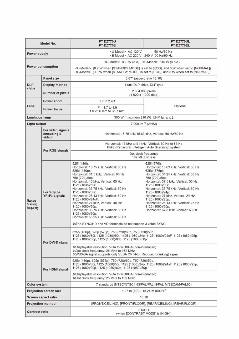
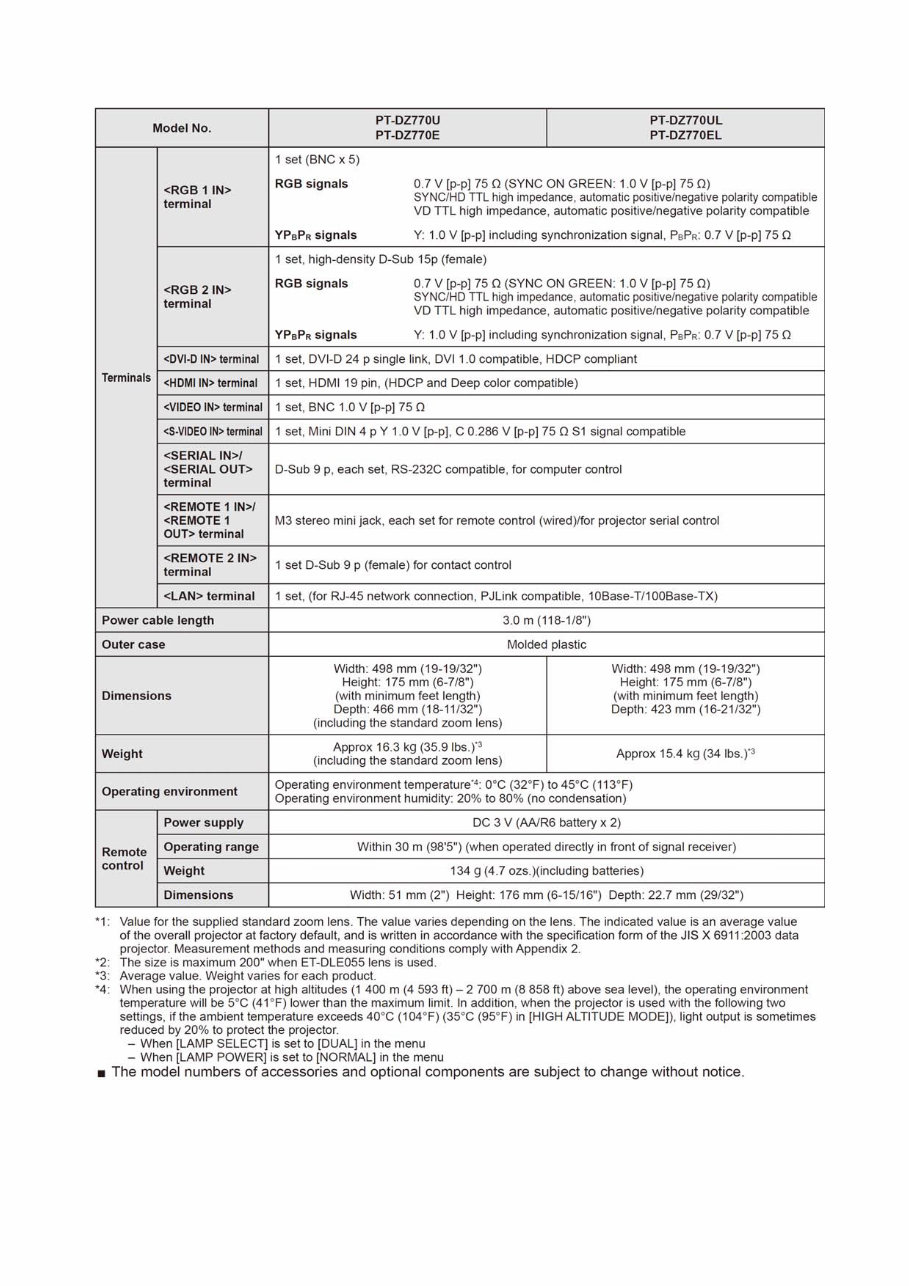
2. Specifications
5
6

1. The name of each part ・・・・・・・・・・・・・・・・・・・・・・・・・・・・・・・・・・・・・・・・・・・・・・・・・・ INF-2
1. 1. Projector body
1. 2. Control panel
1. 3. Connecting terminals
1. 4. Remote control
2. OSD Menu Navigation ・・・・・・・・・・・・・・・・・・・・・・・・・・・・・・・・・・・・・・・・・・・・・・・・・・・ INF-5
3. Service Mode ・・・・・・・・・・・・・・・・・・・・・・・・・・・・・・・・・・・・・・・・・・・・・・・・・・・・・・・・・・ INF-6
3. 1. Setting to Service Mode
3. 2. Resetting to User Mode
3. 3. Function in Service Mode
4. External control ・・・・・・・・・・・・・・・・・・・・・・・・・・・・・・・・・・・・・・・・・・・・・・・・・・・・・・・・・ INF-9
4. 1. Control through SERIAL termanal
4. 2. Control through LAN terminal
5. Notification for service operation ・・・・・・・・・・・・・・・・・・・・・・・・・・・・・・・・・・・・・・・・・・ INF-14
5. 1. Before service operation
5. 2 Service
5. 3. Replacement of consumable parts
5. 4. Initialization for menu lock password
6 Troubleshooting ・・・・・・・・・・・・・・・・・・・・・・・・・・・・・・・・・・・・・・・・・・・・・・・・・・・・・・・・ INF-18
6. 1. Shutdown system
6. 2. Temperature detection, Lamp data, Fan drive Circuit
6. 3. System log data acquisition method
CONTENTS
SECTION 1
< Service Information >
Model No.
PT-DZ770U / DZ770E / DZ770UL / DZ770EL

1. The name of each part
1. 1. Projector body
INF - 2
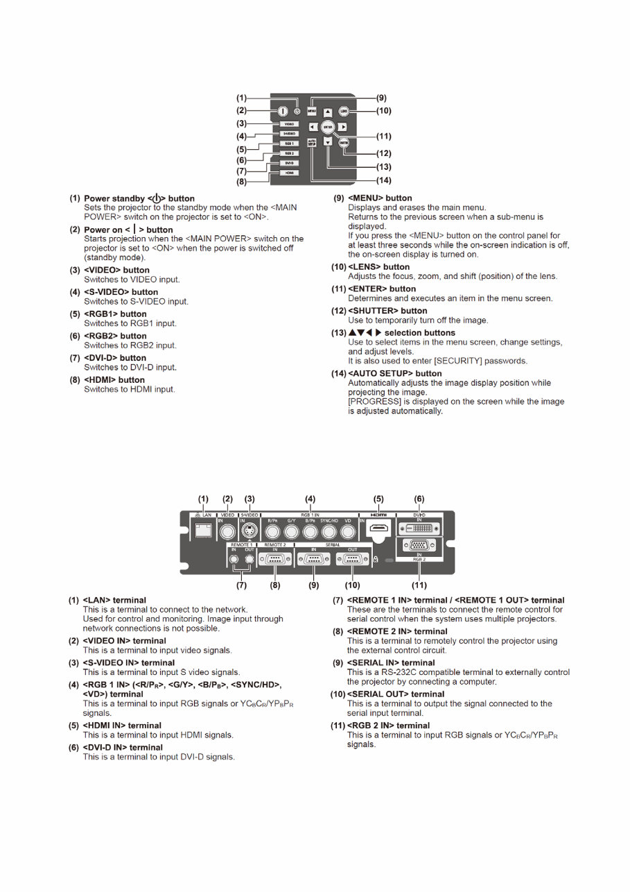
1. 2. Control panel
1. 3. Connecting terminals
INF - 3
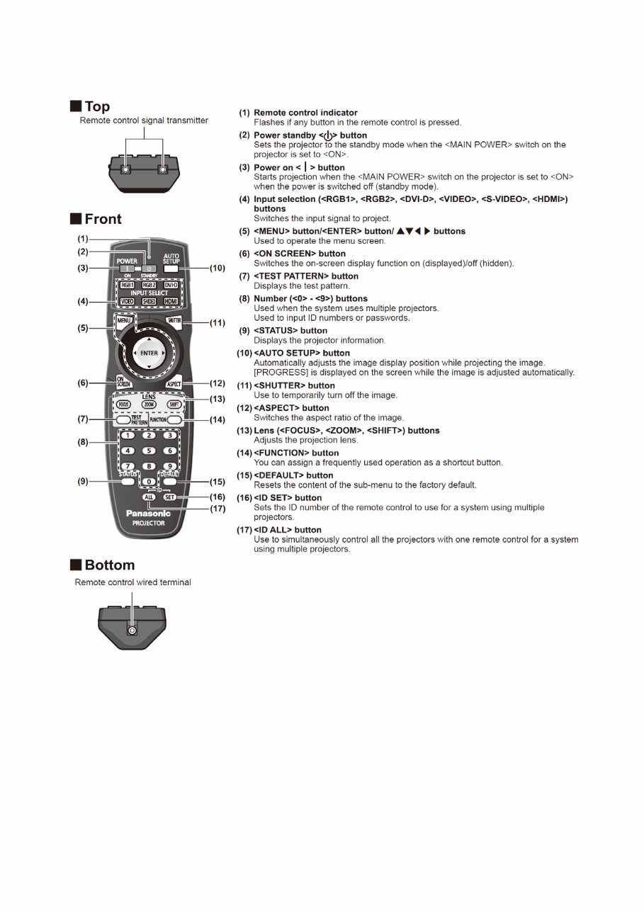
1. 4. Remote control
INF - 4
You're Reading a Preview
What's Included?
Fast Download Speeds
Online & Offline Access
Access PDF Contents & Bookmarks
Full Search Facility
Print one or all pages of your manual
$36.99
Viewed 64 Times Today


Secure transaction
What's Included?
Fast Download Speeds
Online & Offline Access
Access PDF Contents & Bookmarks
Full Search Facility
Print one or all pages of your manual
$36.99
This official service and repair manual for the Panasonic PT-DZ770 DLP based Projector is an essential resource for both professional technicians and DIY enthusiasts. It provides comprehensive guidance on troubleshooting and repairing the projector, covering the following:
- Safety & Precautions
- Product Specifications
- Disassembly & Reassembly
- Troubleshooting
- Adjustments
- Block Diagrams
- Schematic Diagrams
- Circuit Diagrams
- Exploded Views
- Replacement parts list
This detailed manual is illustrated with pictures and step-by-step instructions, ensuring the best approach to servicing and repairing the device. It covers models PT-DZ770U, PT-DZ770E, PT-DZ770UL, and PT-DZ770EL.
It is available in PDF format, ensuring high-resolution quality for printing. With instant access upon payment, there are no shipping fees or waiting for postal delivery, allowing for immediate commencement of repairs.
Specifications:
- Language: English
- Format: PDF
- Pages: 86


