2 PT-AE900U / PT-AE900E Downloaded from www.Manualslib.com manuals search engine
1 Safety Precautions 5 1.1. General Guidelines 5 1.2. Leakage Current Check 5 1.3. UV Precaution and UHM Lamp Precautions 5 2 Ext Option 6 2.1. Procedure to enter EXT OPTION 6 2.2. EXT OPTION Menu and Functions 6 2.3. Canceling EXT OPTION 6 3 Self-Check Mode 7 3.1. Procedure to enter the self-check mode 7 CONTENTS Page Page 3 PT-AE900U / PT-AE900E Downloaded from www.Manualslib.com manuals search engine
3.2. Self Check Display and Contents 8 3.3. Canceling the self-check mode 9 4 Flicker Adjustment Mode 9 4.1. Procedure to enter the adjustment mode 9 4.2. Adjustment Display and Contents 9 4.3. Canceling the flicker adjustment mode 9 5 Using the SERIAL Connector 10 5.1. Connection 10 5.2. Pin Layout and Signal Names for SERIAL Connector 10 5.3. Communication Settings 10 5.4. Basic Format 11 5.5. Control / Query Commands 11 5.6. Communication Cable Specifications 13 5.7. Signal Selector Connecting Cable Specifications 13 6 Disassembly Instructions 14 6.1. Printed Circuit Board and Main Parts Location 14 6.2. Removal of Upper Case 15 6.3. Removal of A-P.C.Board 15 6.4. Removal of S-P.C.Board 15 6.5. Removal of J-P.C.Board 15 6.6. Removal of B/Q-Module 16 6.7. Removal of P-Module 16 6.8. Removal of K-P.C.Board 17 6.9. Removal of Lamp Unit 17 6.10. Removal of Analysis Block 18 6.11. Removal of LCD Block 18 6.12. Removal of Projection Lens 18 6.13. Replacement of LCD Panel 19 6.14. LCD Panel Discrimination 20 6.15. LCD Panel Combination 20 6.16. Replacement of Projection Polarizer 20 6.17. Replacement of Incidence Polarizer 21 6.18. Replacement of PBS Array (Analysis Block) 21 6.19. Removal of Iris Unit 22 7 Measurement and Adjustments 23 7.1. Adjustment Procedure Flowchart 23 7.2. Cautions for Adjustment 23 7.3. Setting Before Adjustment 23 7.4. Convergence Adjustment 23 7.5. Lighting Area Adjustment 24 7.6. Software for Adjustment 26 7.7. Flicker Adjustment 28 7.8. Input Level Adjustment (RGB) 28 7.9. 6130 Revision 29 8 Troubleshooting 30 9 Interconnection Block Diagram 39 9.1. Interconnection Block Diagram (1/2) 39 9.2. Interconnection Block Diagram (2/2) 40 10 Block Diagram 41 10.1. Power Supply 41 10.2. Signal Processing (1/3) 42 10.3. Signal Processing (2/3) 43 10.4. Signal Processing (3/3) 44 11 Schematic Diagram 45 11.1. A-P.C.Board (1/8) 46 11.2. A-P.C.Board (2/8) 47 11.3. A-P.C.Board (3/8) 48 11.4. A-P.C.Board (4/8) 49 11.5. A-P.C.Board (5/8) 50 11.6. A-P.C.Board (6/8) 51 11.7. A-P.C.Board (7/8) 52 11.8. A-P.C.Board (8/8) 53 11.9. K-P.C.Board 54 11.10. J-P.C.Board,S-P.C.Board, H-P.C.Board 55 11.11. B-Module (1/2) 56 11.12. B-Module (2/2) 57 12 Circuit Boards 59 12.1. A-P.CBoard 59 12.2. J-P.C.Board/S-P.C.Board 60 13 Terminal guide of ICs and transistors 61 14 Exploded Views 62 15 Replacement Parts List 66 4 PT-AE900U / PT-AE900E Downloaded from www.Manualslib.com manuals search engine
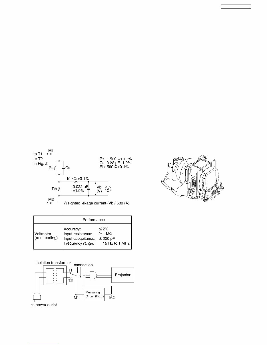
1 Safety Precautions 1.1. General Guidelines · For continued safety, no modification of any circuit must be attempted. · Unplug the power cord from the power outlet before disassembling this projector. · Use correctly the supplied power cord and must ground it. · It is advisable to use an isolation transformer in the AC power line before the service. · Observe the original lead dress during the service. If a short circuit is found, replace all the parts overheated or damaged by the short circuit. · After the service, all the protective devices such as insulation barriers, insulation papers, shields, and isolation R-C combinations must be properly installed. · After the service, check the leakage current to prevent the customer from getting an electric shock. 1.2. Leakage Current Check 1. Prepare the measuring circuit as shown in Fig.1. Be sure to use a voltmeter having the performance described in Table 1. Fig. 1 Table 1 Fig. 2 2. Assemble the circuit as shown in Fig. 2. Plug the power cord in a power outlet. 3. Connect M1 to T1 according to Fig. 2 and measure the voltage. 4. Change the connection of M1 from T1 to T2 and measure the voltage again. 5. The voltmeter must read 0.375 V or lower in both of steps 3 and 4. This means that the current must be 0.75 mA or less. 6. If the reading is out of the above standard, the projector must be repaired and rechecked before returning to the customer because of a possibility of an electric shock. 1.3. UV Precaution and UHM Lamp Precautions · Be sure to unplug the power cord from the power outlet when replacing the lamp. · Because the lamp reaches a very high temperature during its operation, wait until it cools completely when replacing the Lamp Unit. · The lamp emits small amounts of UV-radiation, avoid direct- eye contact with the light. · Because the high pressure lamp involves a risk of explosion, never touch the lamp wire lead during the service. (See Fig. 3) Fig. 3 5 PT-AE900U / PT-AE900E Downloaded from www.Manualslib.com manuals search engine
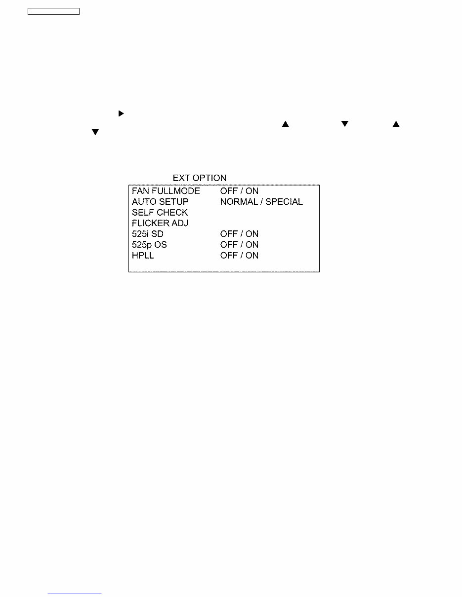
2 Ext Option This projector has EXT OPTION in addition to standard on-screen menus. · There are SELF CHECK and FLICKER ADJ for service, etc. 2.1. Procedure to enter EXT OPTION 1. When the projector is power ON, press "POWER" button on the main unit or remote control unit to display "POWER OFF" confirmation screen. 2. Press the right-arrow " " button to select "CANCEL" in the "POWER OFF" confirmation screen. 3. On the main unit or remote control unit, press the buttons in order of up-arrow " ", down-arrow " ", up-arrow " ", down-arrow " " and "ENTER". (When the "ENTER" button is pressed, "EXT OPTION" menu is displayed.) 2.2. EXT OPTION Menu and Functions · FAN FULLMODE Setting the cooling fan motor rotation speed − − − − Switching ON "FAN FULLMODE", the rotation level of the fan becomes high-speed rotation (fixed). Moreover, when "FAN FULLMODE" is ON, changing "FAN CONTROL" in OPTION becomes impossible (setting FAN FULLMODE is given priority more than FAN CONTROL). · AUTO SETUP Setting AUTO SETUP mode − − − − NORMAL: To set the normal mode (the dot clock is adjusted strictly) − − − − SPECIAL: To set the special mode (the dot clock is adjusted roughly) * Do not change the initial setting (NORMAL). · SELF CHECK To enter the self-check mode · FLICKER ADJ To enter the flicker adjustment mode · 525i SD When non-standard signal of 525i/625i is inputted (AV amplifier, etc.), synchronization might be disordered according to connected equipment. In this case, set 525i SD to ON. · 525p OS When 525p/625p signal is inputted, reflection noise (vertical striated beat) might be generated according to connected equipment. In this case, set 525p OS to ON. However, the resolution decreases a little. · HPLL When non-standard signal of VIDEO/S-VIDEO is inputted (VCR, VHD, etc.), horizontal synchronization might be disordered according to connected equipment. In this case, set HPLL to OFF. 2.3. Canceling EXT OPTION Press "MENU" button on the main unit or remote control unit. 6 PT-AE900U / PT-AE900E Downloaded from www.Manualslib.com manuals search engine
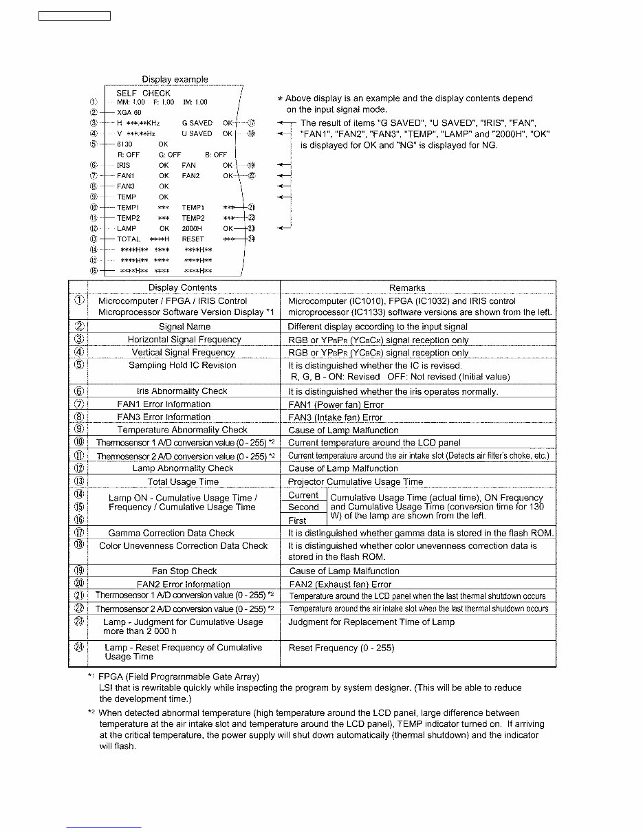
3 Self-Check Mode This mode is used to narrow down the location of the failure. 3.1. Procedure to enter the self-check mode Select "SELF CHECK" on "EXT OPTION" menu and press "ENTER" button on the main unit or remote control unit. 7 PT-AE900U / PT-AE900E Downloaded from www.Manualslib.com manuals search engine
3.2. Self Check Display and Contents 8 PT-AE900U / PT-AE900E Downloaded from www.Manualslib.com manuals search engine
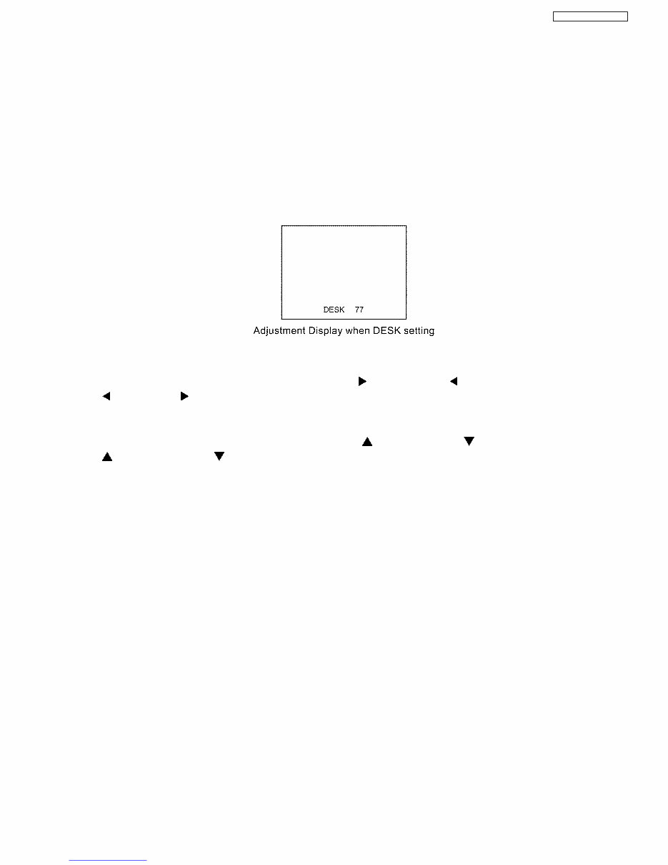
3.3. Canceling the self-check mode Press "MENU" button on the main unit or remote control unit. 4 Flicker Adjustment Mode If replacing the optical parts (LCD Panel / LCD block) or A-P.C.Board of this projector, enter the flicker adjustment mode and minimize the flicker. 4.1. Procedure to enter the adjustment mode Select "FLICKER ADJ" on "EXT OPTION" menu and press "ENTER" button on the main unit or remote control unit. Note: "DESK setting (red)" is displayed when entering the adjustment mode. 4.2. Adjustment Display and Contents · Setting value is increased and decreased with the right-arrow " " and left-arrow " " buttons. " ": Decrease, " ": Increase − − − − Adjust the setting value to minimize the flicker on the screen. − − − − Execute the adjustment by 6 patterns below. · The pattern (adjustment display) is switched with the up-arrow " " and down-arrow " " buttons. " ": Forward direction, " ": Reverse direction − − − − There are 6 patterns of "DESK setting (red)", "DESK setting (blue)", "DESK setting (green)", "CEILING setting (red)", "CEILING setting (blue)" and "CEILING setting (green)". − − − − The setting value is saved into this projector when the pattern is switched. 4.3. Canceling the flicker adjustment mode Press "MENU" button on the main unit or remote control unit. Note: When "MENU" button is pressed, the setting value at that time is saved into this projector and the adjustment mode is canceled. 9 PT-AE900U / PT-AE900E Downloaded from www.Manualslib.com manuals search engine
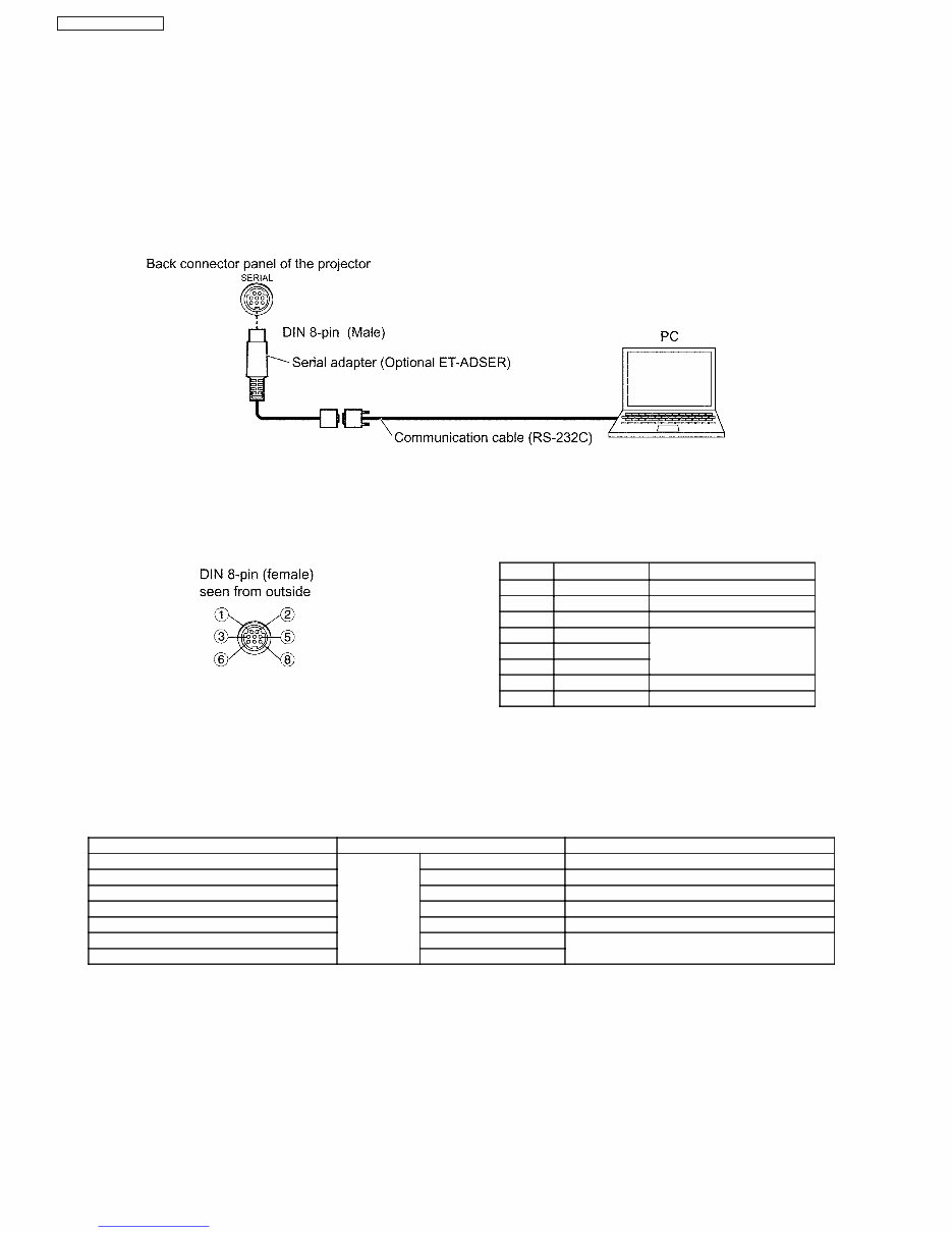
Pin No Signal Name Contents 3 RXD Receive data 4 GND Ground 5 TXD Transmit data 1 --- 2 --- Connected internally 6 --- 7 --- NC 8 --- NC 5 Using the SERIAL Connector The serial connector which is on the back connector panel of the projector conforms to RS-232C standard. This projector can be controlled by a PC which is connected as shown in "5.1. Connection". For controlling this projector by a PC, requires communication software on the market, and inputs control commands according to communication settings and basic format below. 5.1. Connection Note: Use a proper communication cable which is suitable for the PC to connect the optional serial adapter, which is connected with SERIAL connector of this projector, and the PC. 5.2. Pin Layout and Signal Names for SERIAL Connector 5.3. Communication Settings Signal Level Contents Description Sync. method Asynchronous Synchronizes every 1 character (8 bits) Baud rate Conforms to 9 600 bps Data transfer speed Parity RS-232C None Error detection method Character length standard 8 bits Number of bit composing 1 character Stop bit 1 bit Uses stop bit when asynchronous method X parameter Not used S parameter Not used 10 PT-AE900U / PT-AE900E Downloaded from www.Manualslib.com manuals search engine
Are you experiencing issues with your Panasonic PT-AE900 LCD Projector? Instead of spending a significant amount on repairs or replacements, consider taking matters into your own hands with this comprehensive service and repair manual. Trusted by Official Certified Panasonic Technicians, this manual equips you with the knowledge to effectively troubleshoot and repair your projector.
Key features of this manual include:
Safety & Precautions
Product Specifications
Disassembly & Reassembly
Troubleshooting
Adjustments
Block Diagrams
Schematic Diagrams
Circuit Diagrams
Exploded Views
Replacement parts list
This manual covers the following models:
Panasonic PT-AE900
Panasonic PT-AE900U
Panasonic PT-AE900E
Illustrated with detailed pictures and step-by-step instructions, this manual provides in-depth guidance for servicing and repairing your device. It is designed for easy printing from any computer and printer, ensuring accessibility and convenience.
Notably, this is the official service and repair manual in .PDF format, offering high-resolution pages for exceptional print quality. With instant access upon payment, there are no shipping delays, allowing you to commence repairs promptly.
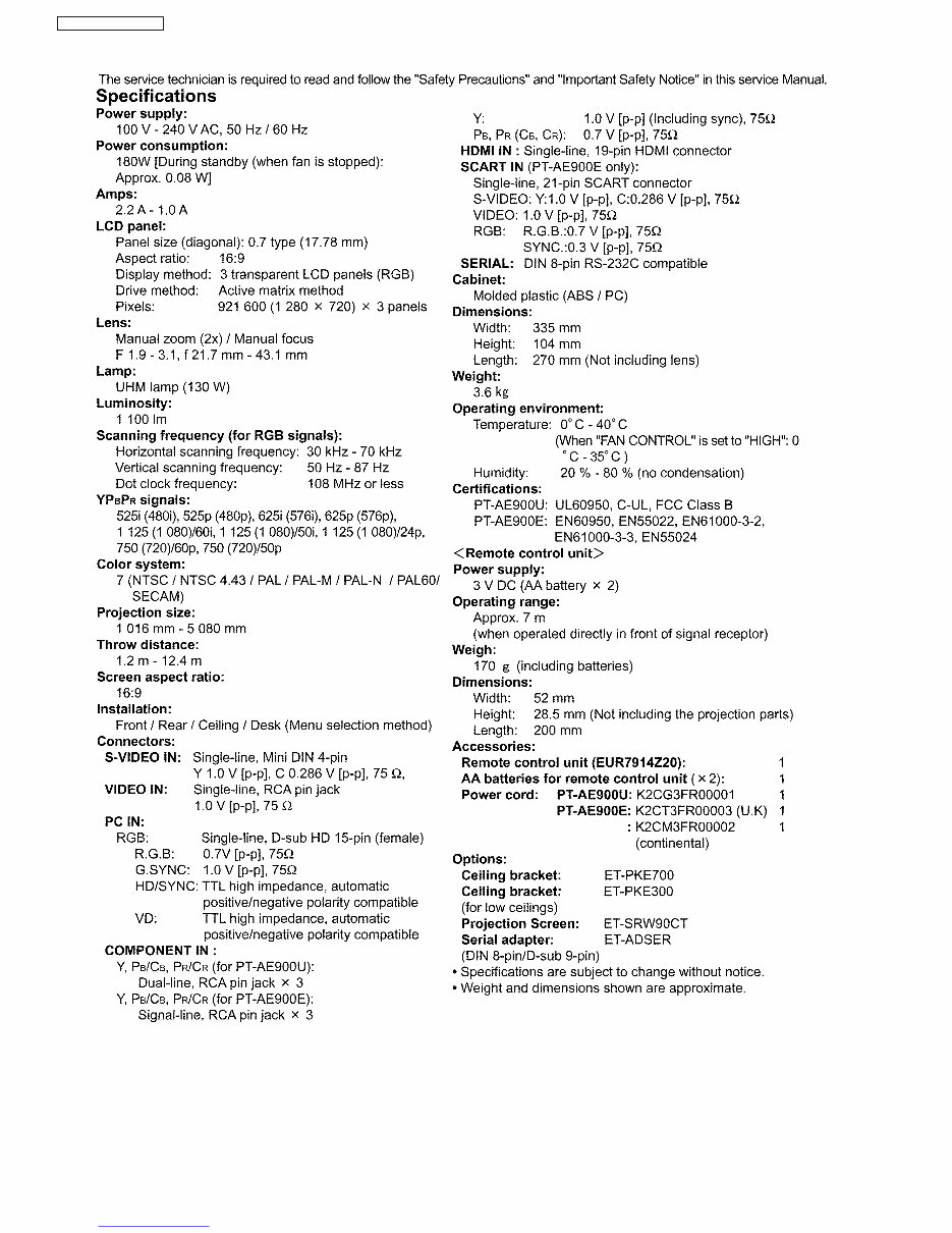
Specifications:
Language: English
Format: .PDF
Pages: 75
Platform: Windows and MAC
If you are unable to locate a specific service manual, feel free to reach out to us. With one of the most extensive service manual databases, we may be able to assist you with your request.