2 4.1. Others (Licenses) ---------------------------------------- 13 5 Location of Controls and Components ------------------ 14 5.1. Remote Control Key Button Operations------------ 14 5.2. Main Unit Key Button Operations -------------------- 15 5.3. Connection to a Broadband Network --------------- 16 5.4. Network Easy Setting ----------------------------------- 17 5.5. Firmware Updates --------------------------------------- 19 5.6. Using BD-LIVE or BONUSVIEW in BD-Video ---- 20 5.7. Enjoying Blu-ray 3D Video ----------------------------- 21 5.8. Using the iPod/iPhone ---------------------------------- 22 5.9. Enjoying VIERA CAST™------------------------------- 24 5.10. Speaker Connections ----------------------------------- 25 5.11. Disc/Card Playability ------------------------------------ 26 5.12. File Extension Type Support (MP3/JPEG/ DivX/AVCHD/MPEG2 files)---------------------------- 28 6 Operating Instructions ---------------------------------------- 30 6.1. Removing of disc during abnomality ---------------- 30 7 Self-Diagnostic and Special Mode Setting ------------- 31 7.1. Special Mode Table 1 -----------------------------------31 7.2. Special Mode Table 2 -----------------------------------32 7.3. Error Code Table -----------------------------------------33 7.4. Service Mode---------------------------------------------- 35 8 Troubleshooting Guide---------------------------------------- 40 8.1. Troubleshooting Guide for F61 and/or F76 -------- 40 9 Service Fixture & Tools --------------------------------------- 44 9.1. Service Tools and Equipment ------------------------- 44 10 Disassembly and Assembly Instructions --------------- 45 10.1. Disassembly Flow Chart-------------------------------- 46 10.2. Main Components and P.C.B. Locations----------- 47 10.3. Disassembly of Top Cabinet--------------------------- 48 10.4. Disassembly of AC Inlet P.C.B.----------------------- 49 10.5. Disassembly of Wireless Adapter P.C.B.----------- 49 10.6. Disassembly of Fan-------------------------------------- 51 10.7. Disassembly of Rear Panel---------------------------- 52 10.8. Disassembly of Front Panel Assembly ------------- 52 10.9. Dissassembly of FL P.C.B.-----------------------------53 10.10. Dissassembly of Power Button P.C.B. --------------55 10.11. Replacement of Cradle Lid ---------------------------- 56 10.12. Disassembly of iPod Cradle Assembly ------------- 57 10.13. Disassembly of iPod P.C.B.----------------------------59 10.14. Replacement of DVD Lid Unit------------------------- 59 10.15. Disassembly of Main P.C.B. ---------------------------62 10.16. Disassembly of Digital P.CB. --------------------------63 10.17. Disassembly of BD Drive------------------------------- 66 10.18. Disassembly of D-Amp P.C.B. ------------------------71 10.19. Replacement of Digital Amplifier IC (IC5100/ IC5200) ----------------------------------------------------- 72 10.20. Disassembly of Power P.C.B. -------------------------73 10.21. Disassembly of SMPS P.C.B. -------------------------73 10.22. Replacement of Switching Regulator IC (IC5701) ---------------------------------------------------- 75 10.23. Replacement of Rectifier Diode (D5702)----------- 76 10.24. Replacement of Regulator Diode (D5802)--------- 77 10.25. Replacement of Regulator Diode (D5803)--------- 78 11 Service Position ------------------------------------------------- 80 11.1. Checking & Repairing Side A of Main P.C.B. -----80 11.2. Checking & Repairing Side B of Main P.C.B. -----80 11.3. Checking & Repairing D-Amp P.C.B.----------------81 11.4. Checking & Repairing SMPS P.C.B. ----------------82 11.5. Checking & Repairing FL P.C.B. ---------------------84 12 Voltage & Waveform Chart ----------------------------------- 85 12.1. Main P.C.B. (1/5)----------------------------------------- 85 12.2. Main P.C.B. (2/5)----------------------------------------- 86 12.3. Main P.C.B. (3/5)----------------------------------------- 87 12.4. Main P.C.B. (4/5)----------------------------------------- 88 12.5. Main P.C.B. (5/5)----------------------------------------- 89 12.6. FL P.C.B. -------------------------------------------------- 90 12.7. D-Amp P.C.B. (1/2)-------------------------------------- 91 12.8. D-Amp P.C.B. (2/2)-------------------------------------- 92 12.9. Power P.C.B. --------------------------------------------- 92 12.10. SMPS P.C.B. --------------------------------------------- 93 12.11. Waveform Table (1/2)----------------------------------- 94 12.12. Waveform Table (2/2)----------------------------------- 95 13 Illustration of ICs, Transistor and Diode ---------------- 96 14 Simplified Block Diagram------------------------------------ 97 15 Block Diagram --------------------------------------------------- 98 15.1. System Control------------------------------------------- 98 15.2. Audio & Video -------------------------------------------- 99 15.3. IC Terminal Chart (Audio & Video) -----------------101 15.4. Power Supply(Main Section) ------------------------102 16 Wiring Connection Diagram ------------------------------- 104 17 Schematic Diagram ------------------------------------------- 105 17.1. Schematic Diagram Notes ---------------------------105 17.2. Main Circuit-----------------------------------------------107 17.3. D-Amp Circuit-------------------------------------------- 115 17.4. SMPS Circuit--------------------------------------------- 119 17.5. Power, Power Button & AC Inlet Circuit-----------121 17.6. iPod & Wireless Adapter Circuit -------------------- 122 17.7. FL Circuit--------------------------------------------------123 18 Printed Circuit Board----------------------------------------- 124 18.1. Main P.C.B.-----------------------------------------------124 18.2. D-Amp P.C.B. --------------------------------------------126 18.3. SMPS P.C.B.---------------------------------------------127 18.4. Power, Power Button, AC Inlet & iPod P.C.B. ---128 18.5. Wireless Adapter & FL P.C.B. -----------------------129 19 Terminal Function of ICs ------------------------------------ 131 19.1. IC6001(C0HBB0000057): IC FL Driver ----------- 131 20 Exploded View and Replacement Parts List ---------- 133 20.1. Exploded View and Mechanical replacement Part List ---------------------------------------------------133 20.2. Electrical Replacement Part List -------------------- 142
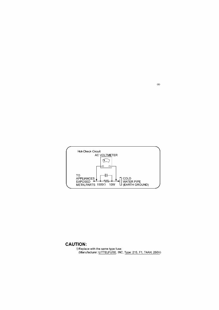
3 1 Safety Precautions 1.1. GENERAL GUIDELINES 1. When servicing, observe the original lead dress. If a short circuit is found, replace all parts which have been overheated or damaged by the short circuit. 2. After servicing, see to it that all the protective devices such as insulation barriers, insulation papers shields are properly installed. 3. After servicing, carry out the following leakage current checks to prevent the customer from being exposed to shock hazards. 1.1.1. LEAKAGE CURRENT COLD CHECK 1. Unplug the AC cord and connect a jumper between the two prongs on the plug. 2. Measure the resistance value, with an ohmmeter, between the jumpered AC plug and each exposed metallic cabinet part on the equipment such as screwheads, connectors, control shafts, etc. When the exposed metallic part has a return path to the chassis, the reading should be between 1MΩ and 5.2MΩ. When the exposed metal does not have a return path to the chassis, the reading must be 1.1.2. LEAKAGE CURRENT HOT CHECK 1. Plug the AC cord directly into the AC outlet. Do not use an isolation transformer for this check. 2. Connect a 1.5kΩ, 10 watts resistor, in parallel with a 0.15µF capacitors, between each exposed metallic part on the set and a good earth ground such as a water pipe, as shown in Figure 1. 3. Use an AC voltmeter, with 1000 ohms/volt or more sensitivity, to measure the potential across the resistor. 4. Check each exposed metallic part, and measure the voltage at each point. 5. Reverse the AC plug in the AC outlet and repeat each of the above measurements. 6. The potential at any point should not exceed 0.75 volts RMS. A leakage current tester (Simpson Model 229 or equivalent) may be used to make the hot checks, leakage current must not exceed 1/2 milliamp. In case a measurement is outside of the limits specified, there is a possibility of a shock hazard, and the equipment should be repaired and rechecked before it is returned to the customer. Figure 1 1.2. Before Repair and Adjustment Disconnect AC power to discharge unit AC Capacitors as such (C5700, C5701, C5702, C5703, C5705, C5706) through a 10 Ω, 10 W resistor to ground. Caution: DO NOT SHORT-CIRCUIT DIRECTLY (with a screwdriver blade, for instance), as this may destroy solid state devices. After repairs are completed, restore power gradually using a variac, to avoid overcurrent. Current consumption at AC 240 V, 60 Hz in NO SIGNAL mode volume minimal should be ~ 600 mA. 1.2.1. Caution for fuse replacement 1.3. Protection Circuitry The protection circuitry may have operated if either of the following conditions are noticed: • No sound is heard when the power is turned on. • Sound stops during a performance. The function of this circuitry is to prevent circuitry damage if, for example, the positive and negative speaker connection wires are “shorted”, or if speaker systems with an impedance less than the indicated rated impedance of the amplifier are used.
4 If this occurs, follow the procedure outlines below: 1. Turn off the power. 2. Determine the cause of the problem and correct it. 3. Turn on the power once again after one minute. Note: When the protection circuitry functions, the unit will not operate unless the power is first turned off and then on again.
5 1.4. Safety Parts Information Safety Parts List: There are special components used in this equipment which are important for safety. These parts are marked by ( ) in the Schematic Diagrams & Replacement Parts List. It is essential that these critical parts should be replaced with manufacturer’s specified parts to prevent shock, fire or other hazards. Do not modify the original design without permission of manufacturer. Safety Ref. No. Part No. Part Name & Description Remarks 9 REX1395-1 1P BLACK WIRE (AC INLET-SMPS) 10 REX1396-1 1P RED WIRE (AC INLET-SMPS) 20 RGR0408A-E2A REAR PANEL BTT350EB/EG 20 RGR0408A-F2A REAR PANEL BTT755EB/EG 32-3 RXQX1013 SMPS BOTTOM PC SHEET UNIT 33 RKM0635-K TOP CABINET 54 VXY2119 BD DRIVE 101 VQL1V70-J LASER CAUTION LABEL A2 K2CQ2CA00007 AC CORD BTT350EG/BTT755EG A2 K2CZ3YY00005 AC CORD BTT350EB/BTT755EB A3 VQT2W19 O/I BOOK (Ge) BTT350EG/BTT755EG A3 VQT2W20 O/I BOOK (It/Fr) BTT350EG/BTT755EG A3 VQT2W21 O/I BOOK (Sp/Du) BTT350EG/BTT755EG A3 VQT2W22 O/I BOOK (Sw/Da) BTT350EG/BTT755EG A3 VQT2W23 O/I BOOK (En) BTT350EB/BTT755EB PCB7 REPX0875BA SMPS P.C.B. (ESD) (RTL) PCB8 REPX0875BA AC INLET P.C.B. (ESD) (RTL) DZ5701 ERZV10V511CS ZNR L5702 ELF21N015A LINE FILTER L5703 ELF21N015A LINE FILTER T5701 ETS42BM1H6AC MAIN TRANSFORMER T5751 ETS19AB2A6AG SUB TRANSFORMER T6100 G4D1A0000142 SWITCHING TRANSFORMER PC5702 B3PBA0000503 PHOTO COUPLER PC5720 B3PBA0000503 PHOTO COUPLER PC5799 B3PBA0000503 PHOTO COUPLER RY701 K6B1AEA00003 RELAY F1 K5D402BNA005 FUSE TH5702 D4CAA5R10001 THERMISTOR P5701 K2AA2B000011 AC INLET C5700 F1BAF1020020 1000pF C5701 F0CAF104A105 0.1uF C5702 F0CAF104A105 0.1uF C5703 F0CAF104A105 0.1uF C5705 F1BAF1020020 1000pF C5706 F1BAF471A013 470pF
You're Reading a Preview
What's Included?
Lifetime Access
Fast Download Speeds
Offline Viewing
Access Contents & Bookmarks
Full Search Facility
Print one or all pages of your manual
$36.99
Panasonic SC-BTT755 Service Manual and Repair Guide
This service and repair manual is an essential guide for troubleshooting and repairing your Panasonic SC BTT755 3D Blu-ray Home Theatre Sound System. It contains detailed information used by Official Certified Panasonic Technicians, making it valuable for both professional mechanics and DIY enthusiasts.
The manual includes safety precautions, service navigation, specifications, installation and operating instructions, troubleshooting guide, disassembly and assembly instructions, schematic diagrams, wiring connection diagrams, and more. It covers models SA-BTT755EB and SA-BTT755EG, providing comprehensive information for both.
Additionally, the manual includes detailed information for the speaker system, covering models SB-HF730P, SB-HC730P, SB-HS735EG, SB-HW330P, and SB-BTT755EG. This section provides in-depth disassembly and assembly instructions, wiring connection diagrams, exploded views, and a complete parts catalog.
Illustrated with pictures and step-by-step instructions, this official service and repair manual is available in PDF format, ensuring high-resolution quality for printing. With instant access upon payment, there are no shipping costs or waiting for postal delivery, allowing you to start repairs immediately.
Specifications:
Language: English
Format: PDF
Pages: 159
Reviews
Q&A
Recently Viewed
5,521,897Happy Clients
2,594,462eManuals
1,120,453Trusted Sellers
15Years in Business
Price:
Actual Price:
Panasonic SC-BTT755 Service Manual and Repair Guide