

ONKYO HT-R320 AV RECEIVER Service Manual
What's Included?
Fast Download Speeds
Online & Offline Access
Access PDF Contents & Bookmarks
Full Search Facility
Print one or all pages of your manual
HT-R320
SERVICE MANUAL SERVICE MANUAL
AV RECEIVER
Silver model
MODEL HT-R320
Ref. No. 3819
082004
SMDD 120V AC, 60Hz
RC-479S
SAFETY-RELATED COMPONENT
WARNING!!
COMPONENTS IDENTIFIED BY MARK ON THE
SCHEMATIC DIAGRAM AND IN THE PARTS LIST ARE
CRITICAL FOR RISK OF FIRE AND ELECTRIC SHOCK.
REPLACE THESE COMPONENTS WITH ONKYO
PARTS WHOSE PART NUMBERS APPEAR AS SHOWN
IN THIS MANUAL.
MAKE LEAKAGE-CURRENT OR RESISTANCE
MEASUREMENTS TO DETERMINE THAT EXPOSED
PARTS ARE ACCEPTABLY INSULATED FROM THE
SUPPLY CIRCUIT BEFORE RETURNING THE
APPLIANCE TO THE CUSTOMER.
Downloaded from www.Manualslib.com manuals search engine

HT-R320
SPECIFICATIONS
Amplifier Section
THD(Total Harmonic Distortion):
Damping Factor:
Input Sensitivity and Impedance:
Output Level and Impedance:
Frequency Response:
Tone Control:
SN Ratio:
Speaker Impedance:
Video Section
Input Sensitivity
/Output Level and Impedance:
Tuner Section
AM
Tuning Frequency Range:
Usable Sensitivity:
S/N Ratio:
THD:
DVD, VIDEO 1, VIDEO 2, VIDEO 3
Video Outputs
A/V Output: MONITOR OUT, VIDEO 1
1 (Optical), 1 (Coaxial)
DVD, MULTICHANNEL, CD, TAPE,
VIDEO 1, VIDEO 2, VIDEO 3
5.1
Specifications and features are subject to change without notice.
Power Output:
Front L/R:
Center
Surround L/R
Dynamic Power:
100 W + 100 W
100 W
100 W + 100 W
(8 , 20 Hz~20 kHz, FTC)
230 W + 230 W (3 , Front)
170 W + 170 W (4 , Front)
115 W + 115 W (8 , Front)
0.08 % (Power Rated)
60 (Front, 1 kHz, 8 )
200 mV/ 47 k (LINE)
200 mV/ 2.2 k (REC OUT)
10 Hz~100 kHz / +0 dB -3 dB (Direct mode)
+12 dB, -12 dB, 50 Hz (BASS)
+12 dB, -12 dB, 20 kHz (TREBLE)
100 dB (CD, IHF-A)
8 ~ 16
1 Vp-p /75 (Composite)
TAPE, VIDEO 1
1
5 + 2
1
530 kHz~1710 kHz
30 μV
40 dB
0.70 %
General
Power Supply:
Power Consumption:
Stand-by Power Consumption:
Dimensions (W H D):
Weight:
AC 120 V, 60 Hz
4.7 A
1.6 W
17-1/8 5-7/8 14-3/4 inches
435 150 374 mm
8.8 kg (19.4 lbs )
FM
Tuning Frequency Range:
Usable Sensitivity:
S/N Ratio:
THD:
Stereo Separation:
Video Inputs
A/V Input:
Audio Inputs
Digital Inputs:
Analog Inputs:
Multichannel Inputs:
Audio Outputs
Analog Outputs:
Subwoofer Pre Outputs:
Speaker Outputs:
Phones:
87.5 MHz~108.0 MHz
Stereo 17.2 dBf 2 μV (75 IHF)
Mono 11.2 dBf 1 μV (75 IHF)
Stereo 70 dB (IHF-A)
Mono 76 dB (IHF-A)
Stereo 0.3 % (1 kHz)
Mono 0.2 % (1 kHz)
45 dB ( 1 kHz )
Downloaded from www.Manualslib.com manuals search engine
SERVICE PROCEDURES
HT-R320
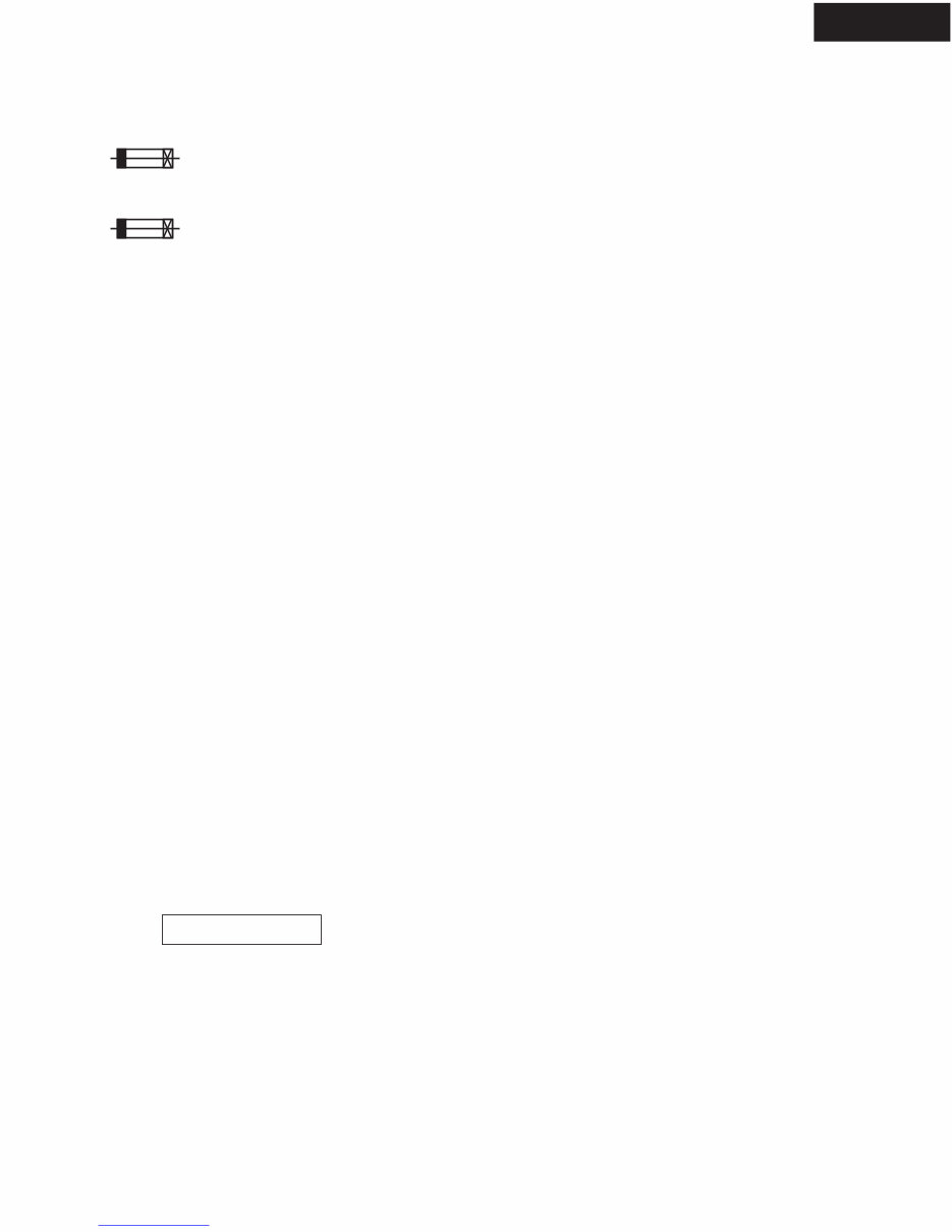
1. Replacing the fuses
2. Safety-check out
(Only U.S.A. model)
After correcting the original service problem perform the
following safety check before releasing the set to the customer
Connect the insulating-resistance tester between the plug of
power supply cord and terminal GND on the back panel.
Specifications: More than 10Mohm at 500V
This symbol located near the fuse indicates that the
fuse used is show operating type, For continued protection against
fire hazard, replace with same type fuse, For fuse rating, refer to
the marking adjacent to the symbol.
Ce symbole indique que le fusible utilise est e lent.
Pour une protection permanente, n'utiliser que des fusibles de meme
type. Ce demier est indique la qu le present symbol est apposre.
3. To initialize the unit
This unit does not require memory preservation batteries.
A built-in memory power backup system preserves the contents of
memory during power failures and even when the power cord is unplugged.
The power cord must be plugged in order to charge the backup system.
The memory preservation period after the unit has been turned off varies
depending on climate and placement of the unit. On average, memory
contents are protected over a period of a few weeks after the time the unit
has been turned off.
This period is shorter when the unit is exposed to a very humid climate.
This device employs a microprocessor to perform various
functions and operations. If interference generated by an external
power supply, radio wave, or other electrical sauce results in accident
which causes the specified operations and functions to operate
abnormally.
To perform a result, please follow the procedure below.
1. Press and the hold down the VIDEO 1 button , then press the
STANDBY/ON button when the unit is Power ON.
2. After " Clear " is displayed, the preset memory and each mode
stored in the memory, are initialized and will return to the
factory settings.
5. Memory Preservation
Main microprocessor Q7008.
1. Press and the hold down the DISPLAY button , then press the
STANDBY/ON button when the unit is Power ON.
Version is displayed on FL display only for 3 seconds.
2. Press the STANDBY/ON button to Power Off.
4. How to check version of microprocessor?
Version 04212a
ex.
REF. NO.
F6901
F6901 or
F6902
F6902 or
F901
F901 or
F903
F903 or
DESCRIPTION
8A-UL
8A-T/UL-ST2
8A-UL
8A-T/UL-ST2
8A-UL
8A-T/UL-ST2
5A-UL/T-237
5A-T/UL-ST2
PART NO.
252198
252261
252198
252261
252198
252261
252164
252258
REMARKS
!
!
!
!
!
!
!
!
Downloaded from www.Manualslib.com manuals search engine
OPERATION CHECK-1
DC VOLTAGE DETECTION PROTECTORS
CURRENT DETECTION PROTECTORS
HT-R320
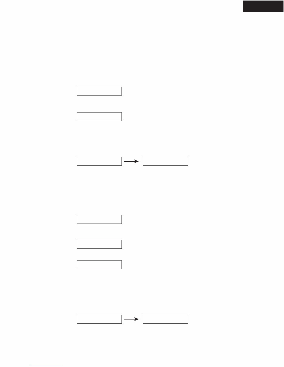
Test - _
Test - 1-00
FL display
Clear
Disappears
0.5 sec.
FL display
Test - _
Test - 4-00
Test - 4-29
Clear
Disappears
1. Set the unit to test mode " Test-1-00 " .
1-1. Press and the hold down the CD button , then press the STANDBY/ON button when the unit is Power ON.
1-2. Press the DVD button, while the " Test - _ " is shown.
Unit will be in the state of " Test-1-00 ".
2. Apply DC voltage (+1.5 to +3V) to MULTI CHANNEL (FL, FR, SL, SR, C) terminal, each channel.
3. Check that " Protect " is shown.
4. Apply DC voltage (-1.5 to -3V) to MULTI CHANNEL (FL, FR, SL, SR, C) terminal, each channel.
5. Check that " Protect " is shown.
6. Press the STANDBY/ON button.
[NOTE1]
Limit time to apply voltage is 0.5 to 1.0 seconds each channel.
When protection operation does not occur at once, try several times.
[NOTE2]
Don't connect speakers or any load.
Don't short speaker terminals.
[NOTE]
In the state of test mode" Test-4-29 ", the pulse waveform output for checking from speaker terminal automatically.
Therefore, oscillator is unnecessary.
1. Set the unit to test mode " Test-4-29 "
1-1. Press and the hold down the CD button , then press the STANDBY/ON button when the unit is Power ON.
1-2. Press the VIDEO 3 button, while the" Test - _ " is shown.
Unit will be in the state of " Test-4-00 ".
1-3. Repeat and press SPEAKERS B button to the " Test-4-29 " is shown.
2. Connect the lord resister (3 ohms) to the speaker terminals.
3. Check that the" Protect " is not shown, and speaker relays not turn OFF.
4. Check the each speaker terminals.
5. Connect the lord resister (1.5 ohms) to the speaker terminals.
6. Check that the " Protect " is shown, and speaker relays turn OFF immediately.
7. Check the each speaker terminals.
8. Press the STANDBY/ON button.
Downloaded from www.Manualslib.com manuals search engine
OPERATION CHECK-2
OUTPUT LEVEL & THERMAL DETECTION
HT-R320
RL6901
D6904
D6903
RL6902
POWER AMP.
PRI. SEC1
Low
High
+B1
-B1 T901 MAIN
TRANSFORMER
Low
High
Q6303
THERMAL
SENSOR
R6380
THERMAL
DETECTION
OUTPUT
LEVEL
DETECTION
VOLH/
THPRO Q7008
MAIN
MICROPROCESSOR
Q6303
SEC1H
23
2
SPEAKER
OUT F6901
F6902
Low-voltage
HIGH
VOLTAGE
MODE
LOW
VOLTAGE
MODE
+/- 63.0 V
+/- 29.0 V
High-voltage
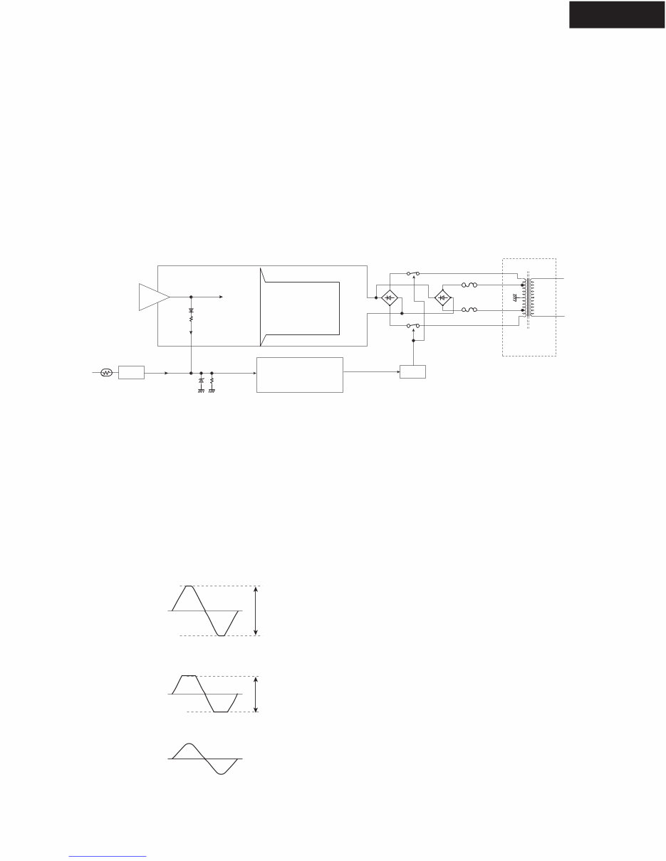
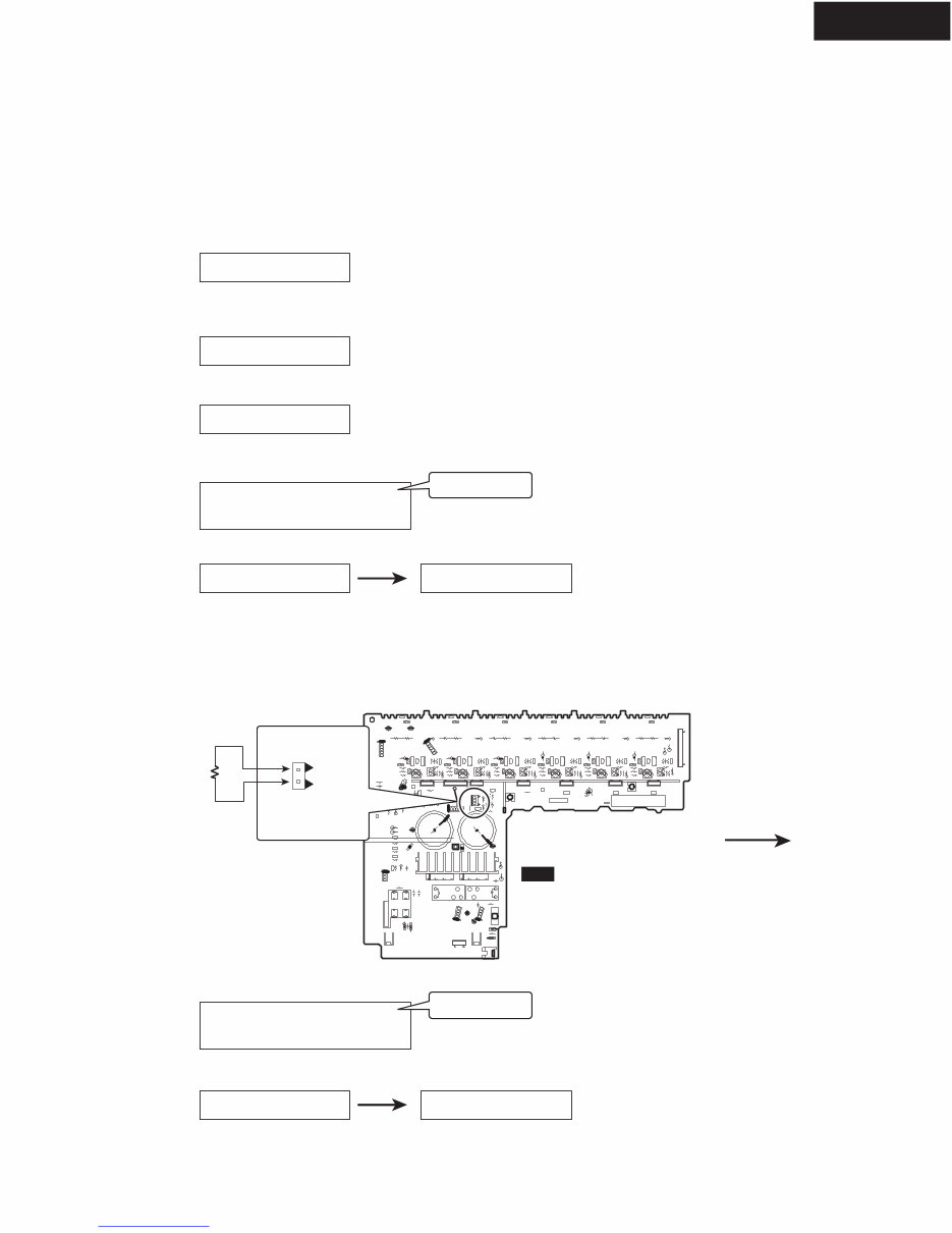
Regarding the power supply system of this unit.
<Function>
1. High-voltage mode
Usually, the power supply supplies high voltage to the power amplifier circuit when the relay (RL6901) is turned On.
2. Low-voltage mode
When as follows, a power supply changes to the state of supplying low voltage when the relay (RL6901) in turned Off.
(1) Excessive output signal is continuously outputted from power amplifier.
(2) Temperature of a heat sink over 80 degrees.
<Purpose>
1. The loss which power amplifier generates is decreased. As a result, the miniaturization of a heat sink is realized.
2. Corresponds to a safety standard.
<Necessity for a check of operation>
May not notice the fuse (F6901, F6902) broken in the case of repair.
Because the power supply is continuing supplying voltage from the High side of SEC1 at high-voltage mode.
When a power supply circuit changes to low voltage mode, amplifier does not operate.
Therefore, it is very important to check operation of this power supply system containing a fuse.
<Procedure>
[NOTE]
Don't connect speakers or any load.
Don't short speaker terminals.
(1) Set the unit is Multi channel input state.
(2) Set the master volume into the minimum.
(3) Apply sine wave signal to MULTI CHANNEL INPUT (FL+FR+C+SL) terminals.
(4) Connect an oscilloscope to speaker terminal of FL channel.
(5) Adjust master volume so that a speaker output may become distortion about 5%.
(6) Check that the RL6901 and RL6902 are turned Off after about 5 seconds progress.
And the power supply changes to low-voltage mode.
(7) Adjust the master volume so that output voltage may become half.
(8) Check that the RL6901 and RL6902 are turned On after 2 to 3 minutes.
And the power supply returns to high-voltage mode.
<Block diagram>
Downloaded from www.Manualslib.com manuals search engine
OPERATION CHECK-3
OUTPUT LEVEL & THERMAL DETECTION
HT-R320
P6301
COM
TH1
TH2
U16
NAAF-8245
POWER AMPLIFIER PC BOARD
P6301
TH1
COM
Front side
2.7 kohms
1W
Test - _
Test - 3-00
Test - 3-02
Test - 3-02
FM STEREO
FM STEREO
Clear
Disappears
0.5 sec.
Clear
Disappears
0.5 sec.
Test - 3-02
FM STEREO
FM STEREO
OUTPUT LEVEL DETECTION
1. Set the unit to test mode " Test-3-2 "
1-1. Press and the hold down the CD button , then press the STANDBY/ON button when the unit is Power On.
1-2. Press the VIDEO 2 button, while the" Test - _ " is shown.
Unit will be in the state of " Test-3-00 ".
1-3. Repeat and press SPEAKERS B to while the " Test-3-2 " is shown.
2. Apply signal (sine wave 1kHz, -1.5dBV) to MULTI CHANNEL (FL, FR, SL, SR, C) terminal, each channel.
3. Check that FM STEREO indicator is shown.
4. Press the STANDBY/ON button.
THERMAL DETECTION
1. Set the unit to test mode " Test-3-2 "
Refer to the clause of "Output level detection".
2. Connect the resistor (2.7 kohms, 1W) between " HT1 " and " COM " terminals of P6301.
3. Check that FM STEREO indicator is shown.
4. Press the STANDBY/ON button.
<Check by test mode>
The following is the procedure of checking detection operation of a microprocessor in false, by using test mode.
Downloaded from www.Manualslib.com manuals search engine
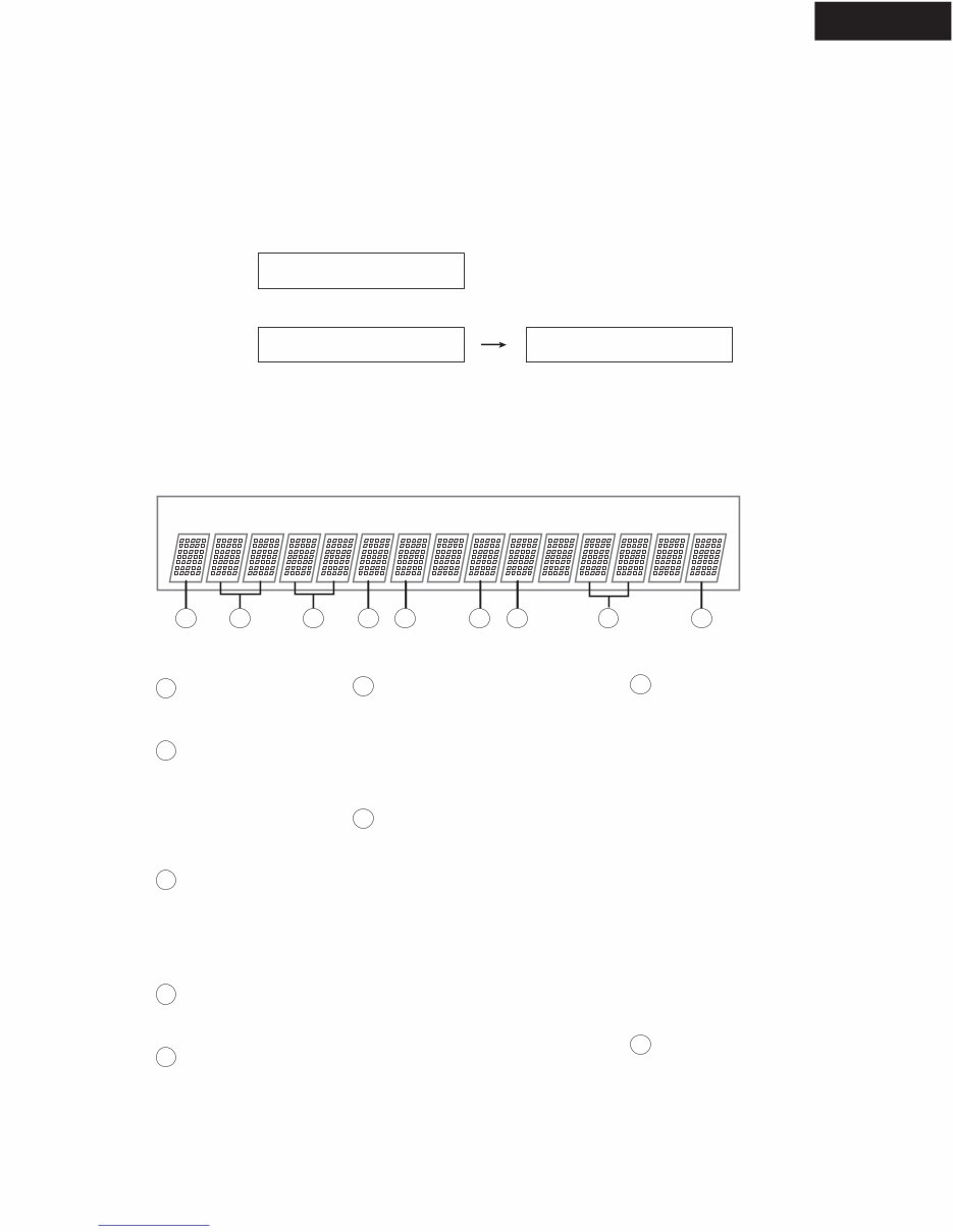
OPERATION CHECK-4
DSP DEBUG MODE
HT-R320
DSP Debug Mode
Version 04212a
E1A---0 -o 23 o
FL display
<Ex.>
Details of FL display
1 4 2 5 6 8 7 9 3
1 sec.
<Regarding the DSP debug mode>
TIn this test mode, the check with normal communication of a microprocessor and the data of DSP and DIR is possible.
This information is a help to find the cause of failure.
UNLOCK
E = UNLOCK
= LOCK
1
Digital Selector
D = DIGITAL
A = ANALOG
1 = COAX
2 = OPT1
3 = OPT2
4 = Others
2
Sampling Frequency
96 = 96kHz
48 = 48kHz
44 = 44kHz
32 = 32kHz
= Not detect
3
MEMORY Address
0 = AC3+PLII
1 = AC3/PCM+T-D
2 = DTS/DTS-ES
3 = DTS
5 = AAC+PL"6" : COS
7 = FACTORY TEST MODE
6
Pre Emphasis
K = OFF
e = ON
4
ROM/RAM Select/Download Status
H = RAM (Complete Auto Boot)
L = ROM (Under Auto boot)
7
DSP Detect Format
[IEC61937]
00 = Null
01= Dolby Digital
03 = Pause
04 = MPEG1 L1
05 = MPEG1 L23/MPEG2 w/o
06 = MPEG2 w/o
07 = MPEG2 AAC
0B = DTS1
0C = DTS2
0D = DTS3
1B = MPEG2 AAC1
1C = MPEG2 AAC2
[Except IEC61937]
20 = Silent
21 = DTS LD
22 = DTS CD
23 = PCM
8
DSP Decode
0 = Decode OK
X = Decode NG
- = Analog in
9
<How to go in DSP debug mode>
1. Press and hold down the DISPLAY button, then press the STANDBY/ON button when the unit is power ON.
2. Press the DISPLAY button, while the" Version 04212a " is shown.
<How to exit>
Press STANDBY/ON button.
<Explanation of each parameter>
DIR MEMORY/DOWNLOAD
DIR Status
0 = PCM/ANALOG
2 = DTS CD
5 = DD/DTS/AAC
5
DSP
Downloaded from www.Manualslib.com manuals search engine
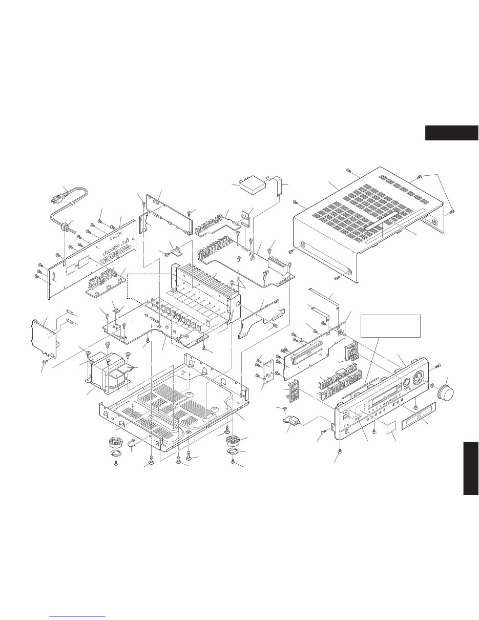
HT-R320
EXPLODED VIEWS-1
HT-R320
U04
U03
P7502
P7503
U02
F903
F6902
F6901
U18
U19
U01
U10
U25
U09
U27
P101
U23
U08
P901
U12
T901
U11
U20
U17
P800
x 8
A028
A035
A020
x 6
A050
A051
x 6
A030
A021
A007
x 3
A005
x 10
A411
A004
A021
A021
x 2
A036
x 2
A025
A024
A404
x 24
A401
A026
A055
x 4
A010
A002
x 2
A421
x 3
A065
A413
A412
A414
A060
A420
A410
A056
x 8
A057
x 4
A017
x 2
A017
A016
x 2
A015
A023
x 4
A435
F901
Refer to
<Fig-1> in
EXPLODED
VIEWS-2
Refer to
<Fig-2> in
EXPLODED VIEWS-2
U26
A022
A425
Downloaded from www.Manualslib.com manuals search engine
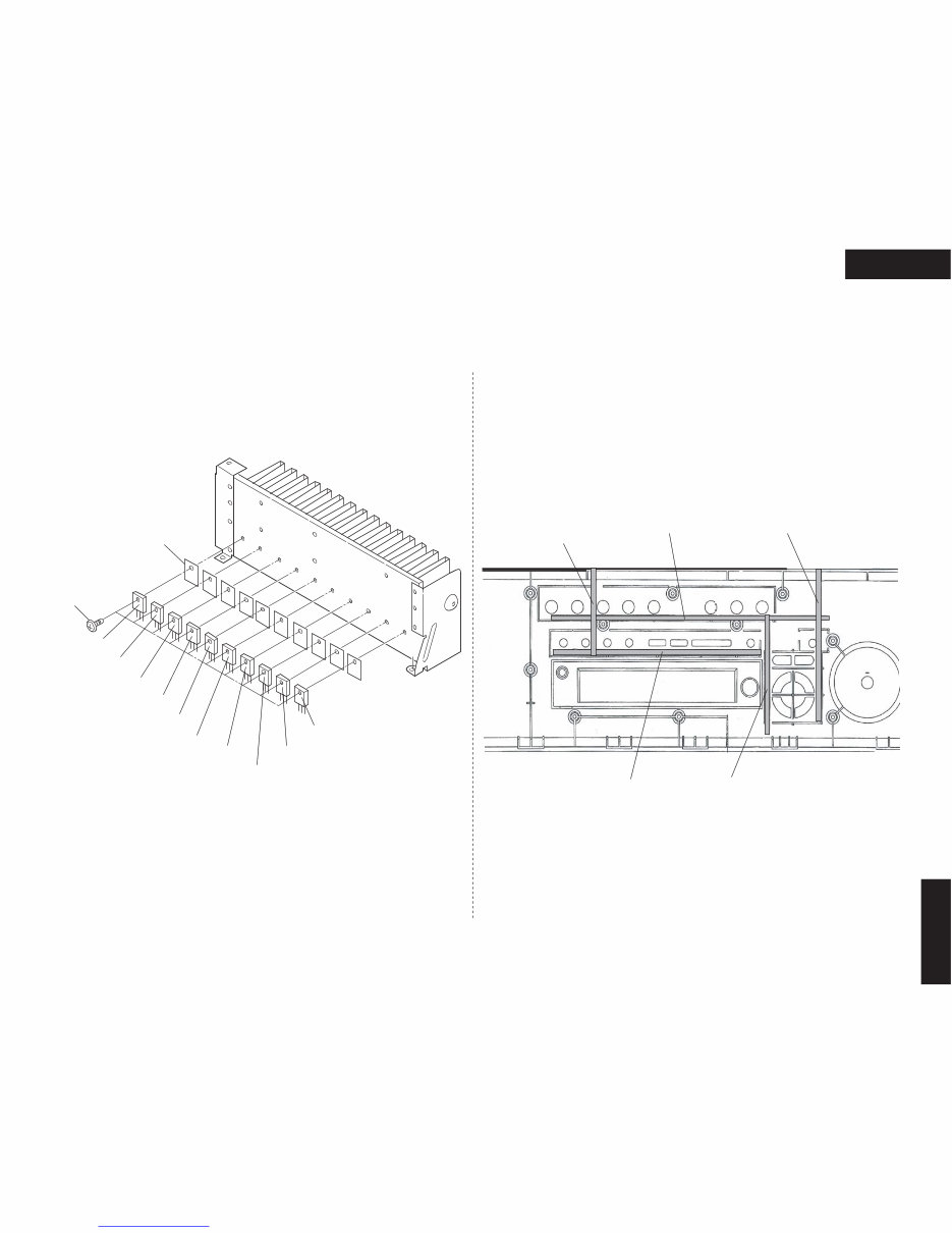
HT-R320
EXPLODED VIEWS-2
HT-R320
Q6064
Q6063
Q6062
Q6061
Q6060
Q6050
Q6051
Q6052
Q6054
Q6053
Q6050A
x10
A037
x10
A416
(L=85mm)
A417
(L=160mm)
<Fig-2> <Fig-1>
FRONT PANEL INSIDE VIEW
A416
(L=85mm)
A415
(L=135mm)
A418
(L=215mm)
Downloaded from www.Manualslib.com manuals search engine
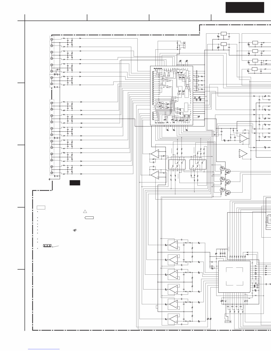
SCHEMATIC DIAGRAMS-1
PRE-AMPLIFIER SECTION
HT-R320
A
1
2
3
4
5
B C D
L805 NC
Q6402
78M12
G
I O
Q6406 78M05
G
I O
Q6405 78M12
G
I O
Q6403 79M12
G
I O
Q321 78L07
G
I O
Q322 79L07
G
I O
P302
VIDEO-3 IN
P261A
NC
P802
NC
P305
DVD
SURROUND R
SURROUND L
SUB WOOFER
CENTER
P304
VIDEO-1 OUT
VIDEO-1 IN
VIDEO-2 IN
P301
CD
TAPE IN
TAPE OUT
Q317
NC
Q319
NC
Q318
NC
TVDD
DVDD
VCOM
DFZ1
LOUT3
ROUT3
LOUT2
ROUT2
LOUT1
ROUT1
LIN
PVDD
VREFH
AVDD
AVSS
DFZ2
CSN
CCLK
CDTI
CDTO
INT1
INT0
SDTI3
SDTI2
PDN
RX1
I2C
RX2
TST
RX3
SLAVE
RX4
PVSS
R
SDTO
BICK
LRCK
MCKO
TX
DVSS
XTI
Q801
AK4586
1
2
3
4
5
6
7
8
9
10
11
12
13
14
15
16
17
18
19
20
21
22
23
24
25
26
27
28
29
30
31
32
33
34
35
36
37
38
39
40
41
42
43
44
L804
022M
NCH-1471
L801
022M
L802
022M
L803
022M
X801
HC-49/U03C
12.288M
T
G 4
1
3
2
Q304
13
1
2
5
4
3
6
8
9
12
11
10
GND
7
VCC
14
Q303
13
1
2
5
4
3
6
8
9
12
11
10
GND
7
VCC
14
LOGIC
BASS BOOST
DA
CL
MUT
VEE
VCC
BASS TREBLE
47k
47k
47k
47k
47k
47k
47k
47k
47k
47k
47k
47k
47k
47k
47k
47k
47k
47k
47k
47k
47k
47k
47k
47k
47k
47k
47k
47k
Q301
BD3811K1
29
70
32
41
44
49
51
53
54
67
56
58
62
60
61
59
47
46
45
66
69
33
40
43
30
10
77
78
21
22
79
80
23
24
1
2
3
4
5
6
7
8
9
11
12
27
26
25
28
15
14
13
16
48
55
19
20
57
17
18
36
37
38
35
71
72
73
74
75
76
63
64
52
50
65
68
34
39
42
31
C375
472J
C373
472J
C374
472J
C372
472J
C371
472J
C376
472J
C849 153J
C841
822J
C344
C342
C343
C341
C339
C338
563J
C337
C340
563J
Q314
NC
Q316
NC
Q315
NC
C816 104Z
D801
D802
C859
10/16
C858
10/16
C353
47/16
C354
47/16
C358
47/16
C357
NC
C356
NC
C355
NC
C854
10/16
C855
47/16
C856
10/16
C857
10/16
C832
10/16
C362
10/16
C349
10/16
C359
10/16
C6412
10/16
C6410
10/16
C6404
10/16
C6406
10/16
C833
10/16
C836
10/16
C837
10/16
C834
10/16
C835
10/16
C809 10/16 C806
220/6.3
C364 10/16
C363 10/16
C801
47/16
C810
47/16
C348
C347
C331
10/16
C329
10/16
C330
10/16
C332
10/16
C333
10/16
C334
10/16
Q305
OR MPC4570
NJM4565M
3
2
4
1
Q302
OR MPC4570
NJM4565M
3
2
4
1
Q802
NJM4565M
5
6
4
7
Q804
NJM4565M
5
6
4
7
Q803
NJM4565M
5
6
4
7
Q305
OR MPC4570
NJM4565M
5
8
6
7
Q302
OR MPC4570
NJM4565M
5
8
6
7
Q802
NJM4565M
3
8
2
1
Q804
NJM4565M
3
8
2
1
Q803
NJM4565M
3
8
2
1
R801 47 NC
R803 47
R347
10K
R348
10K
R366
R365
R364
10K
R363
10K
R316
330
R318
330
R320
330
R339
R321
330
R343 R342
R319
330
R341 R340
R317
330
R338
R310
330
R314
330
R312
330
R333
R311
330
R332
R315
330
R337 R336
R313
330
R335 R334
R304
330
R300
330
R302
330
R306
330
R307
330
R324
R301
330
R323 R322
R303
330
R325 R327
R329 R328
R305
330
R326
R359
NC
R360
NC
R372
R331
470
R371
R330
470
R397
R396
NC
R344
R373
470
R374 47
R375 47
R376
270
R8
47
R387
NC
R386
NC
R358
NC
R368
47K
R367
1K
R369
2.2K
R370
22K
R383 10K
R357
NC
R353
NC
R6410
2.2 1/2W
R6408
R6403
33 1/2W
R6402
10 1/2W
R6407
3.3 1W
R
2
R393
NC
R395
NC
R394
NC
R392
NC
R390
NC
R391
NC
R389
NC
R356
NC
R354
NC
R352
NC
R350
NC
R349
NC
R351
NC
R355
NC
R361 10K
R362 10K
R346
NC
R345
NC
R816
330
R832
100K
R833
100K
R840
2.2K
R841
2.2K
R848
2.2K
R849
2.2K
R844
2.2K
R835
100K
R834
100K
R836
100K
R837
100K
R845
2.2K
R852
2.2K
R853
2.2K
R842
2.2K
R843
2.2K
R850
2.2K
R851
2.2K
R809 1K
R810 1K
R811 220
R812 220
R813 220
R814 220
R807 47
R808 47
R817
330
R818
330
R819
330 R820
10K
R804 47
R805 47
R806 47
R815
18K
C322
104Z
C308
103Z
C6405
223Z
C321 C320 C319 C318 C317 C316 C311 C310 C315 C314 C313
101J
C312
101J
C302
101J
C301 C300 C303
101J
C307 C306 C305 C304
C326
104Z
C325
104Z
C323
104Z
C817
150J
C803
150J
C350
221J
C351
330J
C336 332J
C335
332J
C848 152J
C840
821J
C6411
223Z
C6409
223Z
C6403
223Z
C367
104Z
C366
104Z
C327 330J
C328 330J
C808
104Z
C800
330J
C812
330J
C850 152J
C851 152J
C852 152J
C853 152J
C845
821J
C844
821J
C843
821J
C842
821J
C807
104Z
C811
104Z
C805 104Z
C804 104Z
C802
150J
C815
102K
C814
330J
C813
330J
C346
C345
+7V
CDR
+12VAF
-7V
CDL
TOR -12VAF
TUL
TUR
TOL
+12VVD
V1OL
V1OR
TOL
TOR
V4R
V4L
TUL
TUR
TIR
+5VDSP
CDR
TIL
CDL
TIR
V3IR
TIL
V3IR
V3IL
V2IR
V3IL
V2IL
OUT_L
V1IR
V1IL
OUT_R
DVDR
DVDL
OUT_L
MRS +7V
MLS
MSW -7V
V2IR
MC
ADCL SELMUT
SELCK
ADCR SELDA
OUT_R
V2IL
DAC_R
V1OR OUT_RS
DMIXR
DAC_L
DMIXL
V1OL
OUT_LS
OUT_C
V1IR
OUT_LS
OUT_RS
DAC_RS
DAC_LS
DAC_SW
DAC_C
OUT_C
OUT_SW
OUT_SW
V1IL
OUT_C
DVDR
+12VAF
DAC_SW
DAC_LS DAC_C
DVDL
SNONE
SWNONE
MRS
+7V
-12VAF
MLS
MSW
SNONE -7V
MC
CNONE
DAC_L
SWNONE
DAC_RS
DAC_C
DAC_SW
CNONE
+7V
-7V
+7V
DAC_C
CDTO/SCDO[L]
DIRCS
DSPSCK
DSPDO
INT1[L]
INT0[L]
+3.3V
DAC_SW
CDA
SRDA
LRDA
SDTO
BCK
LRCK
DAC_LS MCK2
DAC_RS
+5VDSP
DAC_L
DIRPD
GND
RX3
RX2
+5VDSP
RX1
TX
DAC_R
ADCL
ADCR
U01
NADG-7401
PRE-AMPLIFIER PC BOARD
<Notes>
NC=No mount of parts.
NC
NC
NC
NC
NC
NC
NC
NC
NC
NC
NC
NC
NC
100/16
100/16 NC
NC
NC
NC
NC NC
NC
NC
NC
NC
NC NC
NC
NC
NC
NC NC NC NC NC
NC
THE COMPONENTS IDENTIFIED BY MARK ARE CRITICAL FOR SAFETY
REPLACE ONLY WITH PART NUMBER SPECIFIED.
VOLTAGE (MEASURED WITH VOLTMETER) IS DC VOLTAGE.(NO INPUT SIGNAL).
ALL PNP TRANSISTORS ARE EQUIVALENT TO 2SA1015-GR UNLESS OTHERWISE NOTED.
ALL NPN TRANSISTORS ARE EQUIVALENT TO 2SC1815-GR UNLESS OTHERWISE NOTED.
ALL DIODES ARE EQUIVALENT TO 1SS133 UNLESS OTHERWISE NOTED.
ELECTROLYTIC CAPACITORS ( ) ARE IN uF/WV.
ALL CAPACITORS ARE IN pF/50WV UNLESS OTHERWISE NOTED.
EX) 030- 3pF 330- 33pF 331- 330pF 333- 0.033uF
ALL RESISTORS ARE IN OHMS 1/4WATTS UNLESS OTHERWISE NOTED.
THE THICK LINES ON PC BOARD ARE THE PRINTING SIDE OF THE PARTS.
EX) PRINTING SIDE
CIRCUIT IS SUBJECT TO CHANGE FOR IMPROVEMENT.
!
NOTE
101
101
101J 101J 101J
101J
101J
101J
101J
101J
101J
101J
101J 101J
101J
101J
23 SDTI1 11
RIN 33 XTO 1
NC
Downloaded from www.Manualslib.com manuals search engine
You're Reading a Preview
What's Included?
Fast Download Speeds
Online & Offline Access
Access PDF Contents & Bookmarks
Full Search Facility
Print one or all pages of your manual
$31.99
Viewed 18 Times Today


Secure transaction
What's Included?
Fast Download Speeds
Online & Offline Access
Access PDF Contents & Bookmarks
Full Search Facility
Print one or all pages of your manual
$31.99
The ONKYO HT-R320 AV RECEIVER Service Manual is an essential resource for anyone involved in the repair and maintenance of this audio-visual equipment. Available in English, this manual provides comprehensive guidance for troubleshooting, disassembly, and reassembly of the ONKYO HT-R320 AV RECEIVER. Whether you are a professional mechanic or a DIY enthusiast, this manual equips you with the necessary technical information to ensure the proper functioning of the AV receiver.


