2 TABLE OF CONTENTS PAGE PAGE 1 Safety Precautions ----------------------------------------------- 3 1.1. General guidelines -----------------------------------------3 2 Warning -------------------------------------------------------------- 4 2.1. Prevention of Electrostatic Discharge (ESD) to Electrostatic Sensitive (ES) Devices ---------------4 2.2. Precaution of Laser Diode -------------------------------5 2.3. Service caution based on legal restrictions----------6 3 Service Navigation------------------------------------------------ 7 3.1. How to format for HDD when replacement of HDD or Power IF P.C.B.----------------------------------7 3.2. Service Information ----------------------------------------8 3.3. Caution for DivX --------------------------------------------8 3.4. Micro Fuse conducting check ---------------------------9 3.5. (HDD/DVD Drive) Service Navigation -------------- 10 3.6. Operation check when a USB device is connected -------------------------------------------------- 11 3.7. Check with Tuner Service Mode --------------------- 11 4 Specifications ---------------------------------------------------- 15 5 Location of Controls and Components ------------------ 17 6 Installation Instructions--------------------------------------- 19 6.1. Taking out the Disc from DVD-Drive Unit when the Disc cannot be ejected by OPEN/CLOSE button-------------------------------------------------------- 19 7 Service Mode ----------------------------------------------------- 21 7.1. Self-Diagnosis and Special Mode Setting---------- 21 8 Service Fixture & Tools --------------------------------------- 38 9 Disassembly and Assembly Instructions --------------- 39 9.1. Unit----------------------------------------------------------- 39 9.2. DVD Drive-------------------------------------------------- 45 10 Measurements and Adjustments -------------------------- 57 10.1. Service Positions ----------------------------------------- 57 10.2. Caution for Replacing Parts --------------------------- 62 10.3. Standard Inspection Specifications after Making Repairs ------------------------------------------- 63
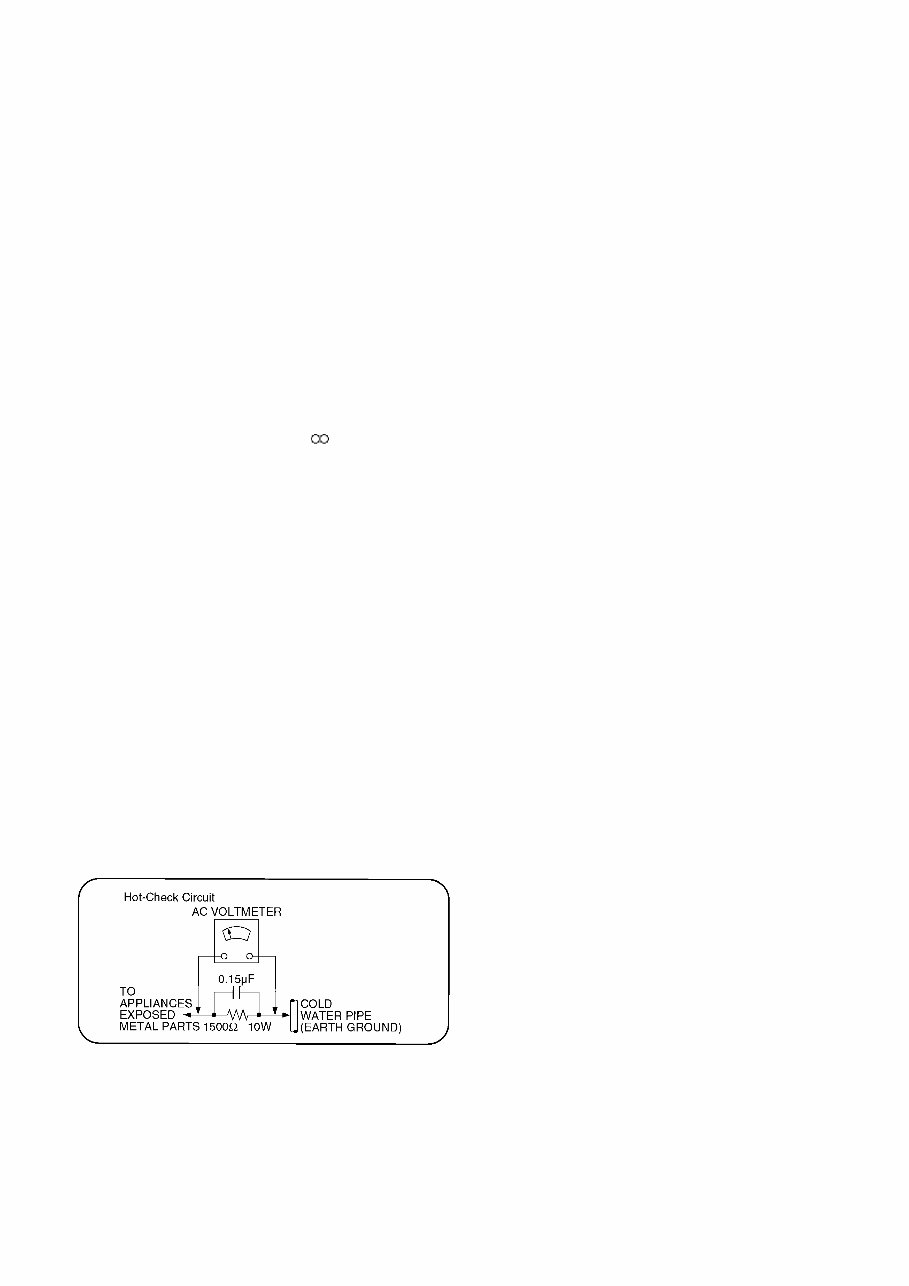
3 1 Safety Precautions 1.1. General guidelines 1. When servicing, observe the original lead dress. If a short circuit is found, replace all parts which have been overheated or damaged by the short circuit. 2. After servicing, see to it that all the protective devices such as insulation barriers, insulation papers shields are properly installed. 3. After servicing, make the following leakage current checks to prevent the customer from being exposed to shock hazards. 1.1.1. Leakage current cold check 1. Unplug the AC cord and connect a jumper between the two prongs on the plug. 2. Measure the resistance value, with an ohmmeter, between the jumpered AC plug and each exposed metal- lic cabinet part on the equipment such as screwheads, connectors, control shafts, etc. When the exposed metal- lic part has a return path to the chassis, the reading should be between 1MΩ and 5.2MΩ. When the exposed metal does not have a return path to the chassis, the reading must be . 1.1.2. Leakage current hot check (See Figure 1.) 1. Plug the AC cord directly into the AC outlet. Do not use an isolation transformer for this check. 2. Connect a 1.5kΩ, 10 watts resistor, in parallel with a 0.15μF capacitors, between each exposed metallic part on the set and a good earth ground such as a water pipe, as shown in Figure 1. 3. Use an AC voltmeter, with 1000 ohms/volt or more sensi- tivity, to measure the potential across the resistor. 4. Check each exposed metallic part, and measure the volt- age at each point. 5. Reverse the AC plug in the AC outlet and repeat each of the above measurements. 6. The potential at any point should not exceed 0.75 volts RMS. A leakage current tester (Simpson Model 229 or equivalent) may be used to make the hot checks, leakage current must not exceed 1/2 milliampere. In case a mea- surement is outside of the limits specified, there is a pos- sibility of a shock hazard, and the equipment should be repaired and rechecked before it is returned to the cus- tomer. Figure 1
4 2 Warning 2.1. Prevention of Electrostatic Discharge (ESD) to Electrostatic Sensitive (ES) Devices Some semiconductor (solid state) devices can be damaged easily by static electricity. Such components commonly are called Elec- trostatic Sensitive (ES) Devices. Examples of typical ES devices are integrated circuits and some field-effect transistor-sand semi- conductor "chip" components. The following techniques should be used to help reduce the incidence of component damage caused by electrostatic discharge (ESD). 1. Immediately before handling any semiconductor component or semiconductor-equipped assembly, drain off any ESD on your body by touching a known earth ground. Alternatively, obtain and wear a commercially available discharging ESD wrist strap, which should be removed for potential shock reasons prior to applying power to the unit under test. 2. After removing an electrical assembly equipped with ES devices, place the assembly on a conductive surface such as alumi- num foil, to prevent electrostatic charge buildup or exposure of the assembly. 3. Use only a grounded-tip soldering iron to solder or unsolder ES devices. 4. Use only an anti-static solder removal device. Some solder removal devices not classified as "anti-static (ESD protected)" can generate electrical charge sufficient to damage ES devices. 5. Do not use freon-propelled chemicals. These can generate electrical charges sufficient to damage ES devices. 6. Do not remove a replacement ES device from its protective package until immediately before you are ready to install it. (Most replacement ES devices are packaged with leads electrically shorted together by conductive foam, aluminum foil or compara- ble conductive material). 7. Immediately before removing the protective material from the leads of a replacement ES device, touch the protective material to the chassis or circuit assembly into which the device will be installed. Caution Be sure no power is applied to the chassis or circuit, and observe all other safety precautions. 8. Minimize bodily motions when handling unpackaged replacement ES devices. (Otherwise harmless motion such as the brushing together of your clothes fabric or the lifting of your foot from a carpeted floor can generate static electricity sufficient to damage an ES device).
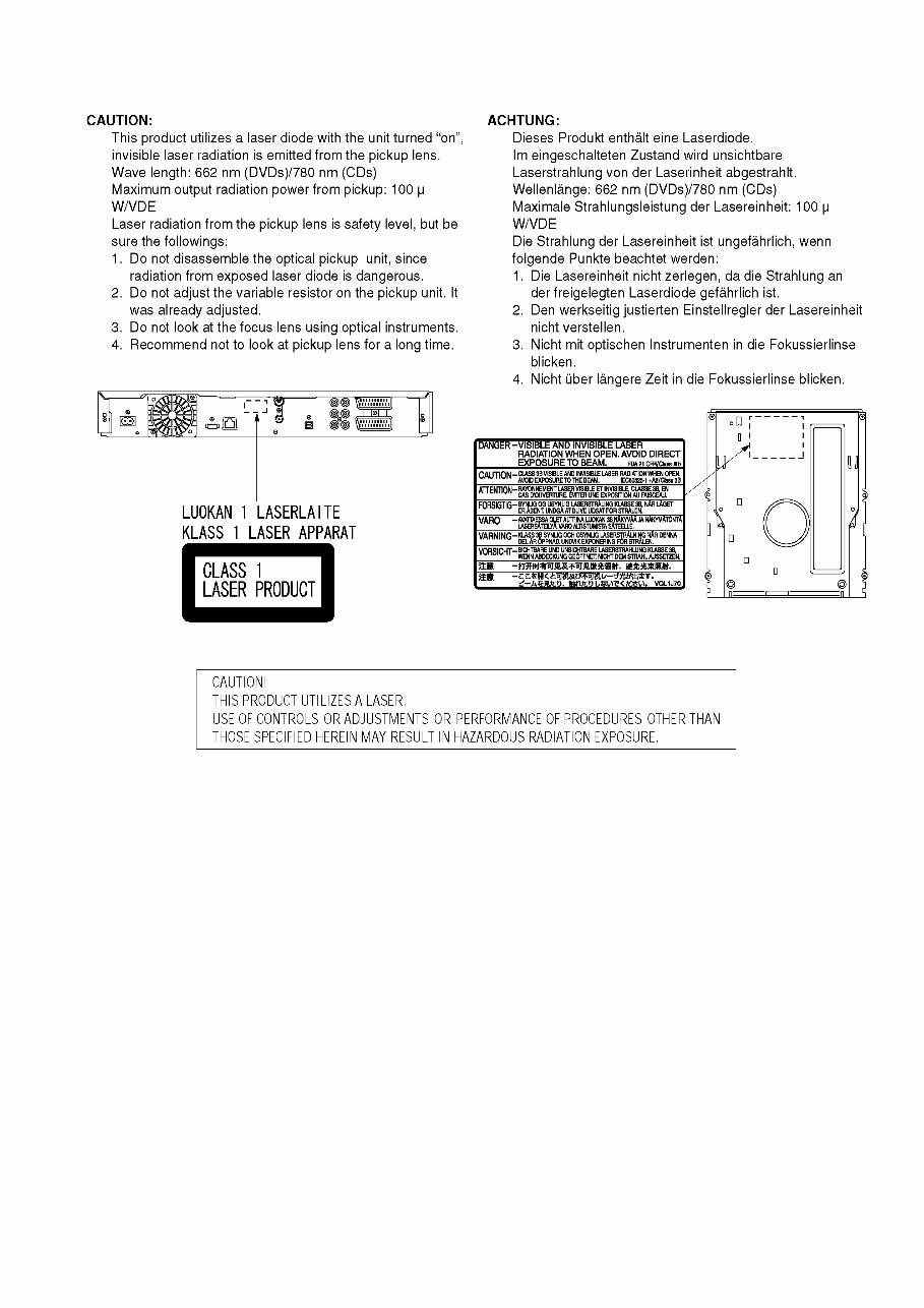
5 2.2. Precaution of Laser Diode
6 2.3. Service caution based on legal restrictions 2.3.1. General description about Lead Free Solder (PbF) The lead free solder has been used in the mounting process of all electrical components on the printed circuit boards used for this equipment in considering the globally environmental conservation. The normal solder is the alloy of tin (Sn) and lead (Pb). On the other hand, the lead free solder is the alloy mainly consists of tin (Sn), silver (Ag) and Copper (Cu), and the melting point of the lead free solder is higher approx.30 degrees C (86°F) more than that of the normal solder. Definition of PCB Lead Free Solder being used Service caution for repair work using Lead Free Solder (PbF) • The lead free solder has to be used when repairing the equipment for which the lead free solder is used. (Definition: The letter of “PbF” is printed on the PCB using the lead free solder.) • To put lead free solder, it should be well molten and mixed with the original lead free solder. • Remove the remaining lead free solder on the PCB cleanly for soldering of the new IC. • Since the melting point of the lead free solder is higher than that of the normal lead solder, it takes the longer time to melt the lead free solder. • Use the soldering iron (more than 70W) equipped with the temperature control after setting the temperature at 350±30 degrees C (662±86°F). Recommended Lead Free Solder (Service Parts Route.) • The following 3 types of lead free solder are available through the service parts route. RFKZ03D01KS-----------(0.3mm 100g Reel) RFKZ06D01KS-----------(0.6mm 100g Reel) RFKZ10D01KS-----------(1.0mm 100g Reel) Note * Ingredient: tin (Sn), 96.5%, silver (Ag) 3.0%, Copper (Cu) 0.5%, Cobalt (Co) / Germanium (Ge) 0.1 to 0.3% The letter of “PbF” is printed either foil side or components side on the PCB using the lead free solder. (See right figure)
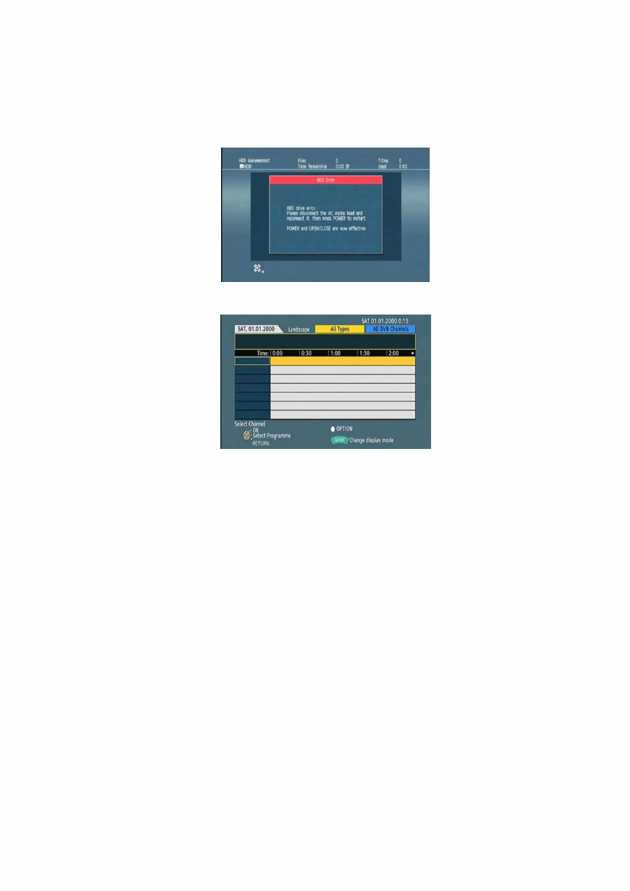
7 3 Service Navigation 3.1. How to format for HDD when replacement of HDD or Power IF P.C.B. 3.1.1. How to escape " HDD Error " indication on GUI display. 1. When exchange HDD or Power IF P.C.B., the " HDD Error " screen is displayed, but, according to a following procedure, please format HDD. 2. Turn off the power button first, then turn on the power with the " GUIDE " button on remote-controller. (Shown in Reference screen 1) (Reference screen 1) 3. Turn on the " RETURN " button next, move to the normal display. 3.1.2. Procedure of the " HDD format ". 1. Turn on the " START " button first, start up the " FUNCTION MENU ". 2. Turn on OK button at the " Others " next, move to the " Setup " stage. 3. Turn on OK button, after choose a position of the " HDD/Disc " at the " Setup " stage. 4. Turn on and hold OK button for over 3 second, after choose a position of the " HDD Management " at the " HDD/Disc " stage. 5. Turn on OK button, after choose a position of the " Format HDD " at the " HDD Management " stage. 6. Turn on OK button, after choose a position of the " Yes " again. 7. Progress to HDD format operation.
8 3.2. Service Information 3.3. Caution for DivX
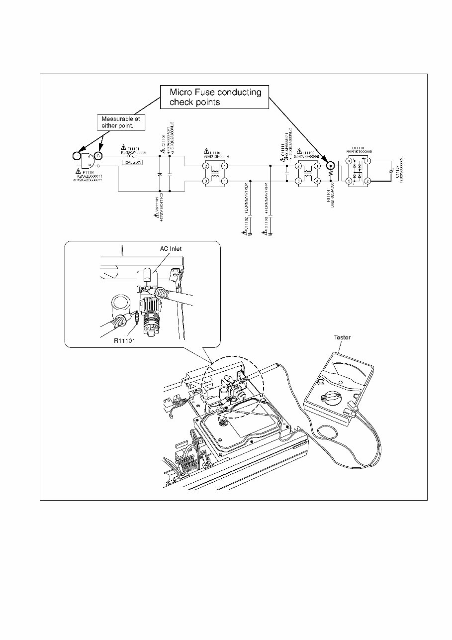
9 3.4. Micro Fuse conducting check This unit uses the Micro Fuse. Check the Micro Fuse conducting using the Tester at the check points below.
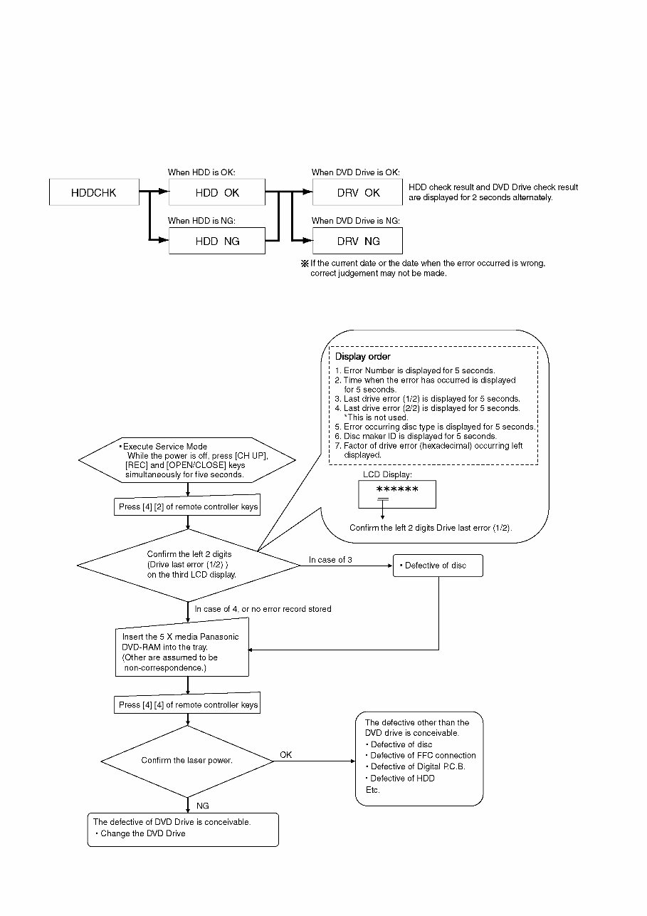
10 3.5. (HDD/DVD Drive) Service Navigation 3.5.1. HDD/DVD Drive Malfunction check (Simplified Method) Perform simple quality judgement process of HDD/DVD Drive according to the following operations. 1. Execute Service Mode While the power is off, press [CH UP], [REC] and [OPEN/CLOSE] keys simultaneously for five seconds. 2. Press [3] [8] of remote controller keys in service mode. 3. Judge the quality on LCD display. 3.5.2. DVD Drive Operation check flow Perform quality judgement process of DVD Drive according to the following operation.
This official service and repair manual for the Panasonic DMR-XW350 XW350EF DVD Recorder is an invaluable resource for both professional mechanics and DIY enthusiasts. It provides comprehensive information on safety and service precautions, specifications and operations, service modes, disassembly and assembly instructions, measurements and adjustments, block diagrams, schematic diagrams, printed circuit boards, exploded views, and a parts list catalog.
It is available in English and comes in a format that allows for instant access without any shipping fees or waiting on postal delivery. The manual is produced in the highest resolution, ensuring that the printed pages are of excellent quality.
With 116 pages of detailed content, this manual is an essential tool for anyone looking to perform repairs or maintenance on the Panasonic DMR-XW350 XW350EF DVD Recorder.
Recently Viewed
5,521,897Happy Clients
2,594,462eManuals
1,120,453Trusted Sellers
15Years in Business
Price:
Actual Price:
Panasonic DMR-XW350 XW350EF Service Manual and Repair Guide