2 TABLE OF CONTENTS PAGE PAGE 1 Safety Precautions ----------------------------------------------- 3 1.1. General guidelines -----------------------------------------3 2 Warning -------------------------------------------------------------- 4 2.1. Prevention of Electrostatic Discharge (ESD) to Electrostatic Sensitive (ES) Devices ---------------4 2.2. Precaution of Laser Diode -------------------------------5 2.3. Service caution based on legal restrictions----------6 3 Service Navigation------------------------------------------------ 7 3.1. Service Information ----------------------------------------7 3.2. Caution for DivX (except DMR-EX773EB)-----------7 3.3. Micro Fuse conducting check ---------------------------8 3.4. Operation check when a USB device is connected ----------------------------------------------------9 4 Specifications ---------------------------------------------------- 10 5 Location of Controls and Components ------------------ 13 6 Operating Instructions ---------------------------------------- 15 6.1. Taking out the Disc from DVD-Drive Unit when the Disc cannot be ejected by OPEN/CLOSE button-------------------------------------------------------- 15 7 Service Mode ----------------------------------------------------- 17 7.1. Self-Diagnosis and Special Mode Setting---------- 17 8 Service Fixture & Tools --------------------------------------- 33 9 Disassembly and Assembly Instructions --------------- 34 9.1. Disassembly Flow Chart-------------------------------- 34 9.2. P.C.B. Positions-------------------------------------------35 9.3. Top Case ---------------------------------------------------36 9.4. Front Panel ------------------------------------------------ 36 9.5. Front (L) P.C.B., Front (R) P.C.B. --------------------37 9.6. HDD --------------------------------------------------------- 37 9.7. Rear Panel, Fan Motor --------------------------------- 38 9.8. RAM/Digital P.C.B. Module ----------------------------38 9.9. Power P.C.B. ----------------------------------------------40 9.10. Main P.C.B. ------------------------------------------------40 10 Measurements and Adjustments -------------------------- 41 10.1. Service Positions ----------------------------------------- 41 10.2. Caution for Replacing Parts --------------------------- 45 10.3. Standard Inspection Specifications after Making Repairs------------------------------------------- 47
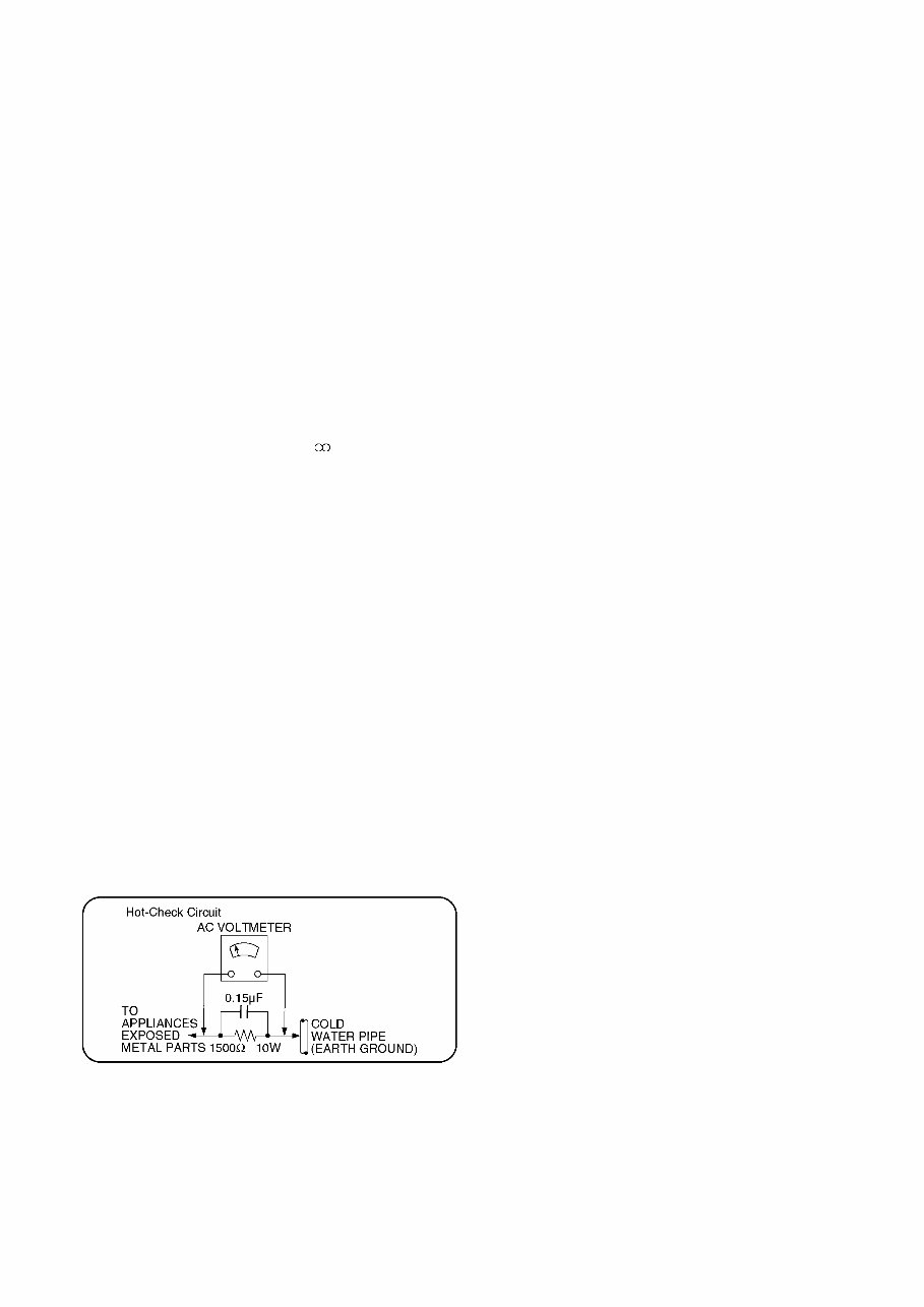
3 1 Safety Precautions 1.1. General guidelines 1. When servicing, observe the original lead dress. If a short circuit is found, replace all parts which have been overheated or damaged by the short circuit. 2. After servicing, see to it that all the protective devices such as insulation barriers, insulation papers shields are properly installed. 3. After servicing, make the following leakage current checks to prevent the customer from being exposed to shock hazards. 1.1.1. Leakage current cold check 1. Unplug the AC cord and connect a jumper between the two prongs on the plug. 2. Measure the resistance value, with an ohmmeter, between the jumpered AC plug and each exposed metal- lic cabinet part on the equipment such as screwheads, connectors, control shafts, etc. When the exposed metal- lic part has a return path to the chassis, the reading should be between 1MΩ and 5.2MΩ. When the exposed metal does not have a return path to the chassis, the reading must be 1.1.2. Leakage current hot check (See Figure 1.) 1. Plug the AC cord directly into the AC outlet. Do not use an isolation transformer for this check. 2. Connect a 1.5kΩ, 10 watts resistor, in parallel with a 0.15μF capacitors, between each exposed metallic part on the set and a good earth ground such as a water pipe, as shown in Figure 1. 3. Use an AC voltmeter, with 1000 ohms/volt or more sensi- tivity, to measure the potential across the resistor. 4. Check each exposed metallic part, and measure the volt- age at each point. 5. Reverse the AC plug in the AC outlet and repeat each of the above measurements. 6. The potential at any point should not exceed 0.75 volts RMS. A leakage current tester (Simpson Model 229 or equivalent) may be used to make the hot checks, leakage current must not exceed 1/2 milliampere. In case a mea- surement is outside of the limits specified, there is a pos- sibility of a shock hazard, and the equipment should be repaired and rechecked before it is returned to the cus- tomer. Figure 1
4 2 Warning 2.1. Prevention of Electrostatic Discharge (ESD) to Electrostatic Sensitive (ES) Devices Some semiconductor (solid state) devices can be damaged easily by static electricity. Such components commonly are called Elec- trostatic Sensitive (ES) Devices. Examples of typical ES devices are integrated circuits and some field-effect transistor-sand semi- conductor "chip" components. The following techniques should be used to help reduce the incidence of component damage caused by electrostatic discharge (ESD). 1. Immediately before handling any semiconductor component or semiconductor-equipped assembly, drain off any ESD on your body by touching a known earth ground. Alternatively, obtain and wear a commercially available discharging ESD wrist strap, which should be removed for potential shock reasons prior to applying power to the unit under test. 2. After removing an electrical assembly equipped with ES devices, place the assembly on a conductive surface such as alumi- num foil, to prevent electrostatic charge buildup or exposure of the assembly. 3. Use only a grounded-tip soldering iron to solder or unsolder ES devices. 4. Use only an anti-static solder removal device. Some solder removal devices not classified as "anti-static (ESD protected)" can generate electrical charge sufficient to damage ES devices. 5. Do not use freon-propelled chemicals. These can generate electrical charges sufficient to damage ES devices. 6. Do not remove a replacement ES device from its protective package until immediately before you are ready to install it. (Most replacement ES devices are packaged with leads electrically shorted together by conductive foam, aluminum foil or compara- ble conductive material). 7. Immediately before removing the protective material from the leads of a replacement ES device, touch the protective material to the chassis or circuit assembly into which the device will be installed. Caution Be sure no power is applied to the chassis or circuit, and observe all other safety precautions. 8. Minimize bodily motions when handling unpackaged replacement ES devices. (Otherwise harmless motion such as the brushing together of your clothes fabric or the lifting of your foot from a carpeted floor can generate static electricity sufficient to damage an ES device).
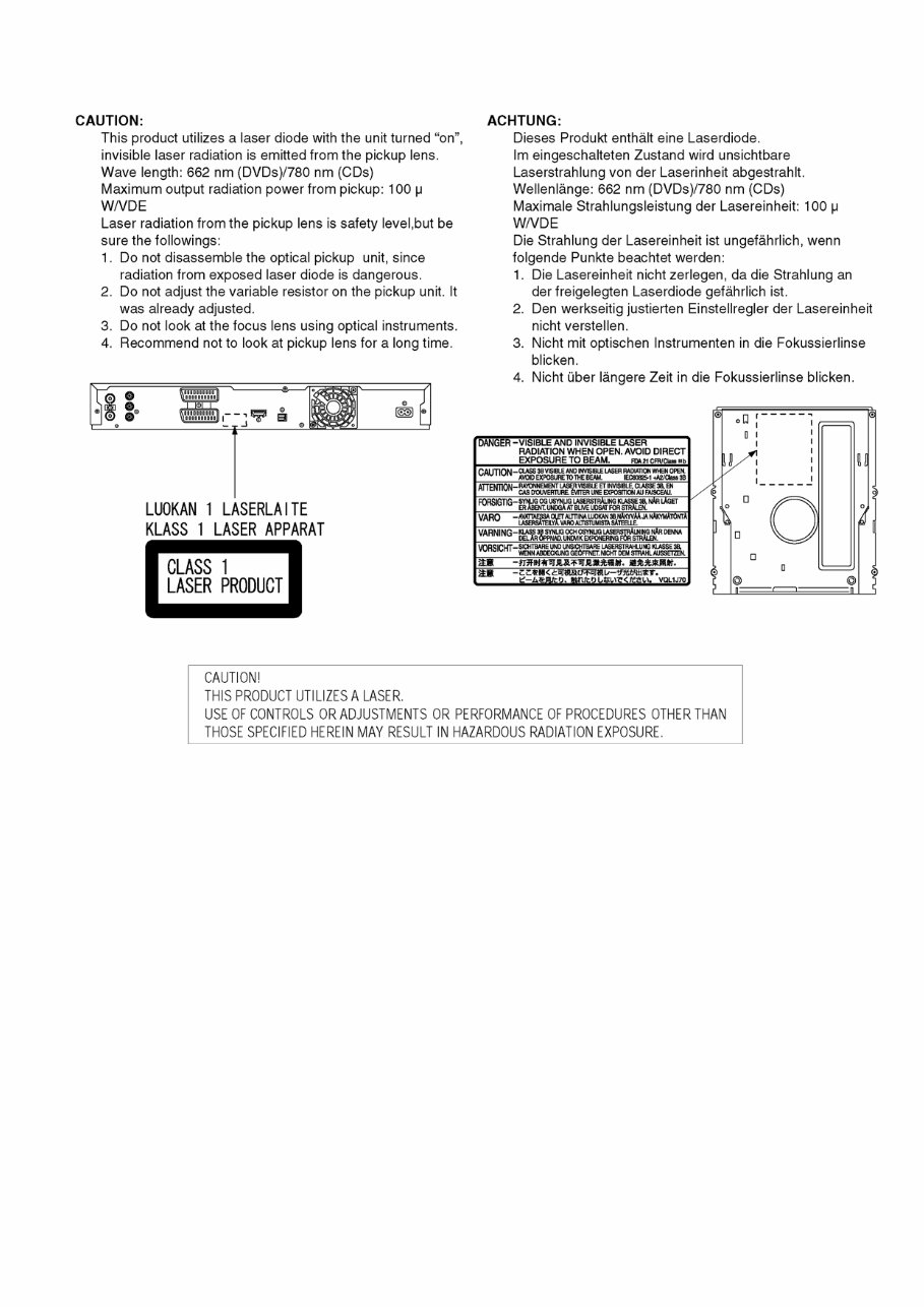
5 2.2. Precaution of Laser Diode
6 2.3. Service caution based on legal restrictions 2.3.1. General description about Lead Free Solder (PbF) The lead free solder has been used in the mounting process of all electrical components on the printed circuit boards used for this equipment in considering the globally environmental conservation. The normal solder is the alloy of tin (Sn) and lead (Pb). On the other hand, the lead free solder is the alloy mainly consists of tin (Sn), silver (Ag) and Copper (Cu), and the melting point of the lead free solder is higher approx.30 degrees C (86°F) more than that of the normal solder. Definition of PCB Lead Free Solder being used Service caution for repair work using Lead Free Solder (PbF) • The lead free solder has to be used when repairing the equipment for which the lead free solder is used. (Definition: The letter of “PbF” is printed on the PCB using the lead free solder.) • To put lead free solder, it should be well molten and mixed with the original lead free solder. • Remove the remaining lead free solder on the PCB cleanly for soldering of the new IC. • Since the melting point of the lead free solder is higher than that of the normal lead solder, it takes the longer time to melt the lead free solder. • Use the soldering iron (more than 70W) equipped with the temperature control after setting the temperature at 350±30 degrees C (662±86°F). Recommended Lead Free Solder (Service Parts Route.) • The following 3 types of lead free solder are available through the service parts route. RFKZ03D01KS-----------(0.3mm 100g Reel) RFKZ06D01KS-----------(0.6mm 100g Reel) RFKZ10D01KS-----------(1.0mm 100g Reel) Note: * Ingredient: tin (Sn), 96.5%, silver (Ag) 3.0%, Copper (Cu) 0.5%, Cobalt (Co) / Germanium (Ge) 0.1 to 0.3% The letter of “PbF” is printed either foil side or components side on the PCB using the lead free solder. (See right figure)
7 3 Service Navigation 3.1. Service Information 3.2. Caution for DivX (except DMR-EX773EB)
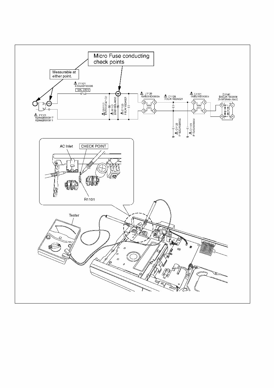
8 3.3. Micro Fuse conducting check This unit uses the Micro Fuse. Check the Micro Fuse conducting using the Tester at the check points below.
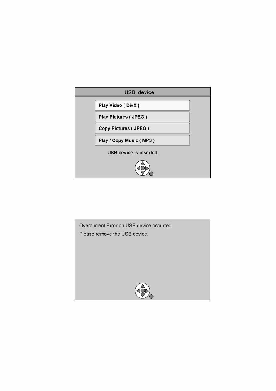
9 3.4. Operation check when a USB device is connected You can check the operation status (normal or abnormal) of the USB connection part of this unit easily as shown below. Connect each device to the USB terminal on the front panel and check the operation status on the TV monitor. Normal operation: Automatically displayed when the USB connection is made to a digital camera, etc. (Example below: When JPEG materials have been recorded) (*Displayed items differ depending on the recorded contents.) Abnormal operation (Example 1): Warning is displayed automatically if overcurrent is detected when a USB device is connected. (*When a USB device or this unit’s USB terminal shorts out or the power supply type of USB device is connected) Abnormal operation (Example 2): When the terminal of USB device is damaged or open, there is no display on the TV monitor.
Are you facing issues with your Panasonic DMR-EX83/EX773 DVD Recorder? Why spend on replacements or costly repairs when you can handle it yourself?
This comprehensive service and repair manual is utilized by Certified Panasonic Technicians and is designed to assist you in troubleshooting and fixing your DVD Recorder.
Key features of this manual include:
Safety & Precautions
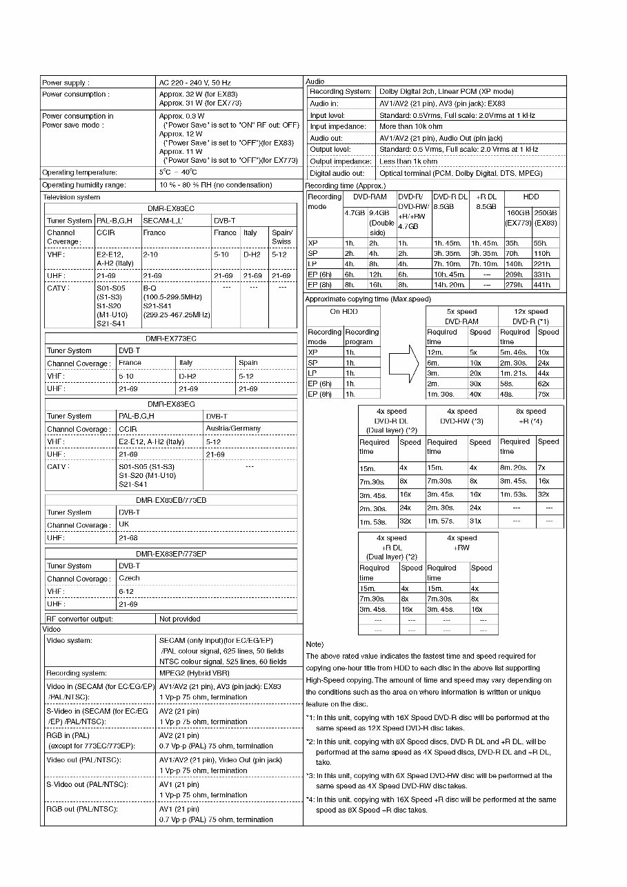
Product Specifications
Disassembly & Reassembly
Adjustments
Maintenance
Troubleshooting
Schematic Diagram
Block Diagram
Replacement Parts list
This manual covers the following models:
Panasonic DMR-EX83EG
Panasonic DMR-EX83EB
Panasonic DMR-EX83EC
Panasonic DMR-EX83EP
Panasonic DMR-EX773EB
Panasonic DMR-EX773EC
Panasonic DMR-EX773EP
It is a highly detailed manual, complete with illustrations and step-by-step instructions for effective device repair and servicing.
Notably, this is the official service and repair manual in PDF format, ensuring the highest resolution for quality printing.
With instant access after payment, there are no shipping fees or waiting for postal delivery, allowing you to commence repairs promptly.
Specifications:
Language: English
Format: PDF
Pages: 100
Platform: Windows and MAC
If you are in search of a specific service manual, feel free to reach out to us. With one of the largest service manual databases, we may be able to assist you!
Recently Viewed
5,521,897Happy Clients
2,594,462eManuals
1,120,453Trusted Sellers
15Years in Business
Price:
Actual Price:
Panasonic DMR-EX83 + EX773 Series Service Manual & Repair Guide