

Panasonic DMR-PWT530 PWT530EB Service Manual and Repair Guide
What's Included?
Fast Download Speeds
Online & Offline Access
Access PDF Contents & Bookmarks
Full Search Facility
Print one or all pages of your manual
© Panasonic Corporation 2013.
Unauthorized copying and distribution is a violation
of law.
ORDER NO.DSD1305007CE
Blu-ray Disc Player
HDD Recorder
Model No. DMR-PWT530EB
DMR-PWT535EC
DMR-PWT635EB
Colour
(K)..................Black Type (only for PWT530EB)
(S)..................Silver Type (except for PWT530EB)
2
3

4
TABLE OF CONTENTS
PAGE PAGE
1 Safety Precautions ----------------------------------------------- 5
1.1. General guidelines -----------------------------------------5
2 Warning -------------------------------------------------------------- 6
2.1. Prevention of Electrostatic Discharge (ESD)
to Electrostatic Sensitive (ES) Devices ---------------6
2.2. Precaution of Laser Diode -------------------------------7
2.3. Service caution based on legal restrictions----------8
2.4. Static Electricity Protection Measures ----------------8
2.5. Ground for electrostatic breakdown
prevention ----------------------------------------------------8
3 Service Navigation---------------------------------------------- 10
3.1. External HDD (USB-HDD) ----------------------------- 10
3.2. How to format for HDD when replacement of
HDD or Main P.C.B. -------------------------------------13
3.3. Combination of Multiple Pressing on the
Remote Control------------------------------------------- 14
3.4. Entering Special Modes with Combination of
Multiple Pressing on the Remote Control ---------- 14
3.5. Service Information -------------------------------------- 16
3.6. Micro Fuse conducting check ------------------------- 17
3.7. (HDD/BDP Drive) Service Navigation--------------- 18
3.8. Operation check when a USB device is
connected -------------------------------------------------- 20
3.9. Wi-Fi Module (Internal) Malfunction Check
(Simplified Method) (PWT535EC/635EB) --------- 21
3.10. Check with Tuner Service Mode --------------------- 23
4 Specifications ---------------------------------------------------- 27
5 Location of Controls and Components ------------------ 29
6 Installation Instructions--------------------------------------- 31
6.1. Taking out the Disc from BDP Drive Unit when
the Disc cannot be ejected by OPEN/CLOSE
button-------------------------------------------------------- 31
7 Service Mode ----------------------------------------------------- 32
7.1. Self-Diagnosis and Special Mode Setting---------- 32
8 Service Fixture & Tools --------------------------------------- 59
9 Disassembly and Assembly Instructions --------------- 60
9.1. Unit----------------------------------------------------------- 60
9.2. BDP Drive -------------------------------------------------- 68
9.3. Disassembly from the traverse unit, assembly
of the optical pick-up unit------------------------------- 75
9.4. Adjustment of BDP Drive/Digital P.C.B. ------------78
10 Measurements and Adjustments -------------------------- 80
10.1. Service Positions ----------------------------------------- 80
10.2. Caution for Replacing Parts --------------------------- 82
10.3. Standard Inspection Specifications after
Making Repairs ------------------------------------------- 82
11 Block Diagram --------------------------------------------------- 83
11.1. Overall Block Diagram ---------------------------------- 83
11.2. Power Supply Block Diagram ------------------------- 84
11.3. Analog Audio Block Diagram-------------------------- 85
11.4. Timer Block Diagram------------------------------------ 86
11.5. Digital P.C.B. Regulator Block Diagram ------------87
11.6. Digital Block Diagram (Front End Section) -------- 88
11.7. Digital Block Diagram (Back End Section)--------- 89
12 Wiring Connection Diagram --------------------------------- 90
12.1. Interconnection Diagram ------------------------------- 90
5
1 Safety Precautions
1.1. General guidelines
1. When servicing, observe the original lead dress. If a short circuit is found, replace all parts which have been overheated or
damaged by the short circuit.
2. After servicing, see to it that all the protective devices such as insulation barriers, insulation papers shields are properly
installed.
3. After servicing, make the following leakage current checks to prevent the customer from being exposed to shock hazards.
1.1.1. Leakage current cold check
1. Unplug the AC cord and connect a jumper between the
two prongs on the plug.
2. Measure the resistance value, with an ohmmeter,
between the jumpered AC plug and each exposed
metallic cabinet part on the equipment such as
screwheads, connectors, control shafts, etc. When the
exposed metallic part has a return path to the chassis, the
reading should be between 1MΩ and 5.2MΩ.
When the exposed metal does not have a return path to
the chassis, the reading must be .
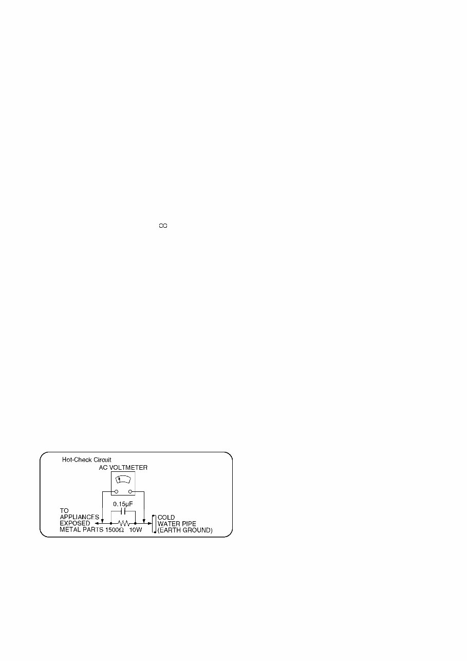
1.1.2. Leakage current hot check
(See Figure 1.)
1. Plug the AC cord directly into the AC outlet. Do not use
an isolation transformer for this check.
2. Connect a 1.5kΩ, 10 watts resistor, in parallel with a
0.15μF capacitors, between each exposed metallic part
on the set and a good earth ground such as a water pipe,
as shown in Figure 1.
3. Use an AC voltmeter, with 1000 ohms/volt or more
sensitivity, to measure the potential across the resistor.
4. Check each exposed metallic part, and measure the
voltage at each point.
5. Reverse the AC plug in the AC outlet and repeat each of
the above measurements.
6. The potential at any point should not exceed 0.75 volts
RMS. A leakage current tester (Simpson Model 229 or
equivalent) may be used to make the hot checks, leakage
current must not exceed 1/2 milliampere. In case a
measurement is outside of the limits specified, there is a
possibility of a shock hazard, and the equipment should
be repaired and rechecked before it is returned to the
customer.
Figure 1
6
2 Warning
2.1. Prevention of Electrostatic Discharge (ESD) to Electrostatic Sensitive
(ES) Devices
Some semiconductor (solid state) devices can be damaged easily by static electricity. Such components commonly are called
Electrostatic Sensitive (ES) Devices. Examples of typical ES devices are integrated circuits and some field-effect transistor-sand
semiconductor "chip" components. The following techniques should be used to help reduce the incidence of component damage
caused by electrostatic discharge (ESD).
1. Immediately before handling any semiconductor component or semiconductor-equipped assembly, drain off any ESD on your
body by touching a known earth ground. Alternatively, obtain and wear a commercially available discharging ESD wrist strap,
which should be removed for potential shock reasons prior to applying power to the unit under test.
2. After removing an electrical assembly equipped with ES devices, place the assembly on a conductive surface such as
aluminum foil, to prevent electrostatic charge buildup or exposure of the assembly.
3. Use only a grounded-tip soldering iron to solder or unsolder ES devices.
4. Use only an anti-static solder removal device. Some solder removal devices not classified as "anti-static (ESD protected)" can
generate electrical charge sufficient to damage ES devices.
5. Do not use freon-propelled chemicals. These can generate electrical charges sufficient to damage ES devices.
6. Do not remove a replacement ES device from its protective package until immediately before you are ready to install it. (Most
replacement ES devices are packaged with leads electrically shorted together by conductive foam, aluminum foil or
comparable conductive material).
7. Immediately before removing the protective material from the leads of a replacement ES device, touch the protective material
to the chassis or circuit assembly into which the device will be installed.
Caution
Be sure no power is applied to the chassis or circuit, and observe all other safety precautions.
8. Minimize bodily motions when handling unpackaged replacement ES devices. (Otherwise harmless motion such as the
brushing together of your clothes fabric or the lifting of your foot from a carpeted floor can generate static electricity sufficient
to damage an ES device).
7
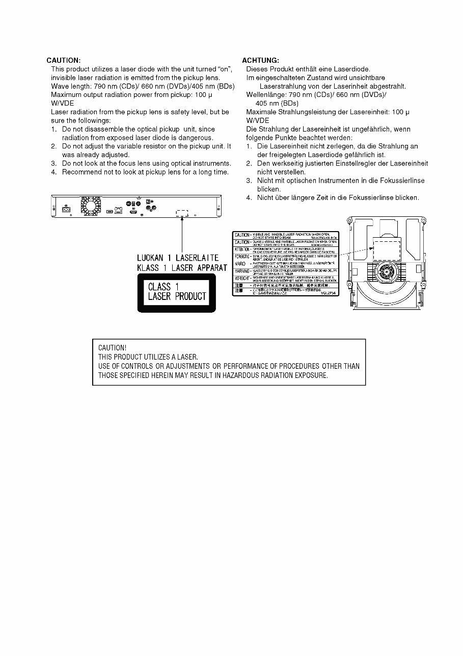
2.2. Precaution of Laser Diode

8
2.3. Service caution based on legal restrictions
2.3.1. General description about Lead Free Solder (PbF)
The lead free solder has been used in the mounting process of all electrical components on the printed circuit boards used for this
equipment in considering the globally environmental conservation.
The normal solder is the alloy of tin (Sn) and lead (Pb). On the other hand, the lead free solder is the alloy mainly consists of tin
(Sn), silver (Ag) and Copper (Cu), and the melting point of the lead free solder is higher approx.30 degrees C (86°F) more than that
of the normal solder.
Definition of PCB Lead Free Solder being used
Service caution for repair work using Lead Free Solder (PbF)
• The lead free solder has to be used when repairing the equipment for which the lead free solder is used.
(Definition: The letter of "PbF" is printed on the PCB using the lead free solder.)
• To put lead free solder, it should be well molten and mixed with the original lead free solder.
• Remove the remaining lead free solder on the PCB cleanly for soldering of the new IC.
• Since the melting point of the lead free solder is higher than that of the normal lead solder, it takes the longer time to melt the
lead free solder.
• Use the soldering iron (more than 70W) equipped with the temperature control after setting the temperature at 350±30 degrees
C (662±86°F).
Recommended Lead Free Solder (Service Parts Route.)
• The following 3 types of lead free solder are available through the service parts route.
RFKZ03D01KS-----------(0.3mm 100g Reel)
RFKZ06D01KS-----------(0.6mm 100g Reel)
RFKZ10D01KS-----------(1.0mm 100g Reel)
Note
* Ingredient: tin (Sn), 96.5%, silver (Ag) 3.0%, Copper (Cu) 0.5%, Cobalt (Co) / Germanium (Ge) 0.1 to 0.3%
2.4. Static Electricity Protection Measures
• The laser diode in the traverse unit (optical pick-up) may break down due to potential difference caused by static electricity of
clothes or human body.
So, be careful of electrostatic breakdown during repair of the traverse unit (optical pick-up).
2.5. Ground for electrostatic breakdown prevention
• As for parts that use optical pick-up (laser diode), the optical pick-up is destroyed by the static electricity of the working
environment.
Repair in the working environment that is grounded.
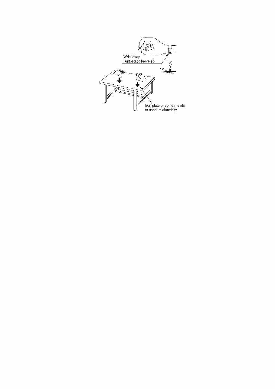
2.5.1. Work table grounding
• Put a conductive material (sheet) or steel sheet on the area where the traverse unit (optical pick-up) is placed, and ground the
sheet.
The letter of "PbF" is printed either foil side or components side on the PCB using the lead free solder.
(See right figure)
9
2.5.2. Human body grounding
• Use the anti-static wrist strap to discharge the static electricity from your body.
2.5.3. When exchange the BDP Drive
• Before remove the ESD prevention bag, make sure to use the anti-static wrist strap to discharge the static electricity when
replace the BDP Drive.
Note:
The ESD prevention bag is used to replace the original short-circuit point.
It can be removed while placing the BDP Drive.
10
3 Service Navigation
3.1. External HDD (USB-HDD)
• Certain non-confirmed USB-HDDs cannot be used with this unit.
• If a problem occurs with the USB-HDD, please contact the manufacturer of the device.
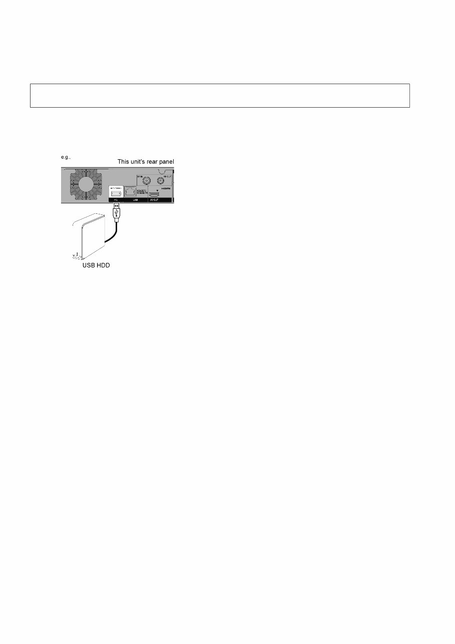
3.1.1. Connecting the USB-HDD
Connect this unit with optional USB-HDD.
• Only one USB-HDD (For recorded titles) can be connected
at the same time.
• Do not connect additional HDDs using a USB hub.
• For details about connection method, refer to the
instructions supplied with the USB-HDD.
3.1.2. Disconnecting the USB-HDD
Please use the following procedure to disconnect.
Disconnecting without following this procedure may result in the loss of recorded content from the USB-HDD or the internal HDD.
1. Press [SETUP].
2. Select "Settings for USB-HDD" in "HDD/ Disc/ USB-HDD", then press [OK].
3. Select "USB HDD Disconnection", then press [OK].
4. Select "Yes", then press [OK].
5. Disconnect the USB-HDD from this unit.
3.1.3. Registering the USB-HDD
3.1.3.1. Registering the USB-HDD
• If you use a USB-HDD with this unit, the USB-HDD must first be registered on this unit.
- Registering of a USB-HDD will format the USB-HDD and all the content already recorded will be deleted.
- Up to eight USB-HDDs can be registered on this unit.
- Registered USB-HDDs cannot be used with devices other than this unit.
• If the registering screen appears when connecting the USB-HDD, go to step 4.
1. Press [SETUP].
2. Select "Settings for USB-HDD" in "HDD/ Disc/ USB-HDD", then press [OK].
3. Select "USB-HDD Registration", then press [OK].
4. Select "Yes", then press [OK].
• If you have already registered eight USB-HDDs, it will be necessary to delete one or more of them before registering a
new USB-HDD.
The message screen appears:
1. Select "Yes", then press [OK].
2. Select the USB-HDD to cancell, then press [OK]. The confirmation screen appears.
3. Select "Yes", then press [OK].
5. When the registering is complete, message screen appears.
Press [OK].
6. The confirmation screen appears.
Press [OK].
Please use a confirmed USB-HDD.
For the latest information on confirmed USB-HDDs, please check the following website.
http://panasonic.jp/support/global/cs/
You're Reading a Preview
What's Included?
Fast Download Speeds
Online & Offline Access
Access PDF Contents & Bookmarks
Full Search Facility
Print one or all pages of your manual
$35.99
Viewed 66 Times Today


Secure transaction
What's Included?
Fast Download Speeds
Online & Offline Access
Access PDF Contents & Bookmarks
Full Search Facility
Print one or all pages of your manual
$35.99
This official service and repair manual for the Panasonic DMR-PWT530 PWT530EB Blu Ray Recorder is an invaluable resource for both professional technicians and DIY enthusiasts.
- Provides comprehensive information on safety & precautions
- Includes detailed product specifications
- Covers disassembly & reassembly procedures
- Offers measurements & adjustments guidance
- Facilitates self diagnostics & troubleshooting
- Features block diagrams and wiring connection diagrams
Rest assured, this manual is not a scanned-in or bootlegged copy. It is created in the highest resolution, ensuring excellent print quality for the pages you need. With instant access, there are no shipping fees or waiting on postal delivery, allowing you to commence repairs promptly.
Specifications:
- Language: English
- Format: PDF
- Pages: 90


