

Yamaha RX-Z1/DSP-AZ1 Service Manual
What's Included?
Fast Download Speeds
Online & Offline Access
Access PDF Contents & Bookmarks
Full Search Facility
Print one or all pages of your manual
SERVICE MANUAL
101069
IMPORTANT NOTICE
This manual has been provided for the use of authorized YAMAHA Retailers and their service personnel.
It has been assumed that basic service procedures inherent to the industry, and more specifically YAMAHA Products, are already
known and understood by the users, and have therefore not been restated.
WARNING: Failure to follow appropriate service and safety procedures when servicing this product may result in personal
injury, destruction of expensive components, and failure of the product to perform as specified. For these reasons,
we advise all YAMAHA product owners that any service required should be performed by an authorized
YAMAHA Retailer or the appointed service representative.
IMPORTANT: The presentation or sale of this manual to any individual or firm does not constitute authorization, certification or
recognition of any applicable technical capabilities, or establish a principle-agent relationship of any form.
The data provided is believed to be accurate and applicable to the unit(s) indicated on the cover. The research, engineering, and
service departments of YAMAHA are continually striving to improve YAMAHA products. Modifications are, therefore, inevitable
and specifications are subject to change without notice or obligation to retrofit. Should any discrepancy appear to exist, please
contact the distributor's Service Division.
WARNING: Static discharges can destroy expensive components. Discharge any static electricity your body may have
accumulated by grounding yourself to the ground buss in the unit (heavy gauge black wires connect to this buss).
IMPORTANT: Turn the unit OFF during disassembly and part replacement. Recheck all work before you apply power to the unit.
■ CONTENTS
TO SERVICE PERSONNEL .......................................... 2
FRONT PANELS ........................................................ 4–5
REAR PANELS ........................................................ 6–10
REMOTE CONTROL PANELS .................................... 11
SPECIFICATIONS / 参考仕様 ................................ 12–16
INTERNAL VIEW ......................................................... 17
DISASSEMBLY PROCEDURES / 分解手順.......... 18–28
UPDATING FIRMWARE /
ファームウェアの書き込み ..................................... 29–38
SELF-DIAGNOSTIC FUNCTION /
ダイアグ(自己診断機能) ..................................... 40–85
AMP ADJUSTMENT / アンプ部調整 ........................... 86
DISPLAY DATA ..................................................... 90–91
IC DATA ............................................................... 92–107
PIN CONNECTION DIAGRAMS ........................ 108–110
BLOCK DIAGRAMS .......................................... 111–119
PRINTED CIRCUIT BOARDS ............................ 120–158
SCHEMATIC DIAGRAMS .................................. 159–179
REPLACEMENT PARTS LIST .......................... 181–235
REMOTE CONTROL .......................................... 236–240
ADVANCED SETUP /
アドバンストセットアップメニューを設定する ..... 241–242
AV RECEIVER/AV AMPLIFIER
P.O.Box 1, Hamamatsu, Japan
2008 All rights reserved.
This manual is copyrighted by YAMAHA and may not be copied or
redistributed either in print or electronically without permission.
'08.02
RX-Z11/DSP-Z11
RX-Z11/DSP-Z11
RX-Z11/DSP-Z11
2
RX-Z11/DSP-Z11
WALL
OUTLET
EQUIPMENT
UNDER TEST
AC LEAKAGE
TESTER OR
EQUIVALENT
INSULATING
TABLE
WARNING: CHEMICAL CONTENT NOTICE!
This product contains chemicals known to the State of California to cause cancer, or birth defects or other reproductive
harm.
DO NOT PLACE SOLDER, ELECTRICAL/ELECTRONIC OR PLASTIC COMPONENTS IN YOUR MOUTH FOR ANY
REASON WHAT SO EVER!
Avoid prolonged, unprotected contact between solder and your skin! When soldering, do not inhale solder fumes or expose
eyes to solder/flux vapor!
If you come in contact with solder or components located inside the enclosure of this product, wash your hands before
handling food.
1. Critical Components Information
Components having special characteristics are marked s
and must be replaced with parts having specifications equal
to those originally installed.
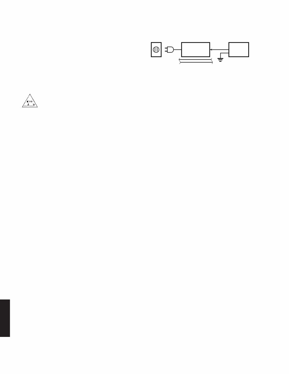
2. Leakage Current Measurement (For 120V Models Only)
When service has been completed, it is imperative to verify
that all exposed conductive surfaces are properly insulated
from supply circuits.
● Meter impedance should be equivalent to 1500 ohms shunted
by 0.15µF.
● Leakage current must not exceed 0.5mA.
● Be sure to test for leakage with the AC plug in both polarities.
本機に搭載されているすべての基板およびハンダ付けによる接合
部は無鉛ハンダでハンダ付けされています。
無鉛ハンダにはいくつかの種類がありますが、修理時には下記の
ような無鉛ハンダの使用を推奨します。
・Sn+Ag+Cu(錫+銀+銅)
・Sn+Cu(錫+銅)
・Sn+Zn+Bi (錫+亜鉛+ビスマス)
注意:
無鉛ハンダの融点温度は通常の鉛入りハンダに比べ30~40℃
程度高くなっていますので、それぞれのハンダに合ったハンダ
ごてをご使用ください。
All of the P.C.B.s installed in this unit and solder joints are
soldered using the lead free solder.
Among some types of lead free solder currently available,
it is recommended to use one of the following types for the
repair work.
• Sn + Ag + Cu (tin + silver + copper)
• Sn + Cu (tin + copper)
• Sn + Zn + Bi (tin + zinc + bismuth)
Caution:
As the melting point temperature of the lead free solder is
about 30°C to 40°C (50°F to 70°F) higher than that of the lead
solder, be sure to use a soldering iron suitable to each solder.
About lead free solder / 無鉛ハンダについて
■ TO SERVICE PERSONNEL
For U model
“CAUTION”
“F1: FOR CONTINUED PROTECTION AGAINST RISK OF FIRE, REPLACE ONLY WITH SAME TYPE 4A,
125V FUSE.”
“F2: FOR CONTINUED PROTECTION AGAINST RISK OF FIRE, REPLACE ONLY WITH SAME TYPE 15A,
125V FUSE.”
For C model
CAUTION
F1: REPLACE WITH SAME TYPE 4A, 125V FUSE.
F2: REPLACE WITH SAME TYPE 15A, 125V FUSE.
ATTENTION
F1: UTILISER UN FUSIBLE DE RECHANGE DE MÉME TYPE DE 4A, 125V.
F2: UTILISER UN FUSIBLE DE RECHANGE DE MÉME TYPE DE 15A, 125V.

RX-Z11/DSP-Z11
3
RX-Z11/DSP-Z11
CAUTION
Danger of explosion if battery is incorrectly replaced.
Replace only with the same or equivalent type.
WARNING: Lithium batteries
注意
正しい電池と交換しないと爆発が起きるおそれがあります。
同一型名または同等品以外の電池とは絶対に交換しないようにし
てください。
WARNING: Lithium batteries are dangerous because
they can be exploded by improper handling. Observe the
following precautions when handling or replacing lithium
batteries.
• Leave lithium battery replacement to qualified service
personnel.
• Always replace with batteries of the same type.
• When installing on the PC board by soldering, solder
using the connection terminals provided on the battery
cells. Never solder directly to the cells. Perform the
soldering as quickly as possible.
• Never reverse the battery polarities when installing.
• Do not short the batteries.
• Do not attempt to recharge these batteries.
• Do not disassemble the batteries.
• Never heat batteries or throw them into fire.
ADVARSEL!
Lithiumbatteri –Eksplosionsfare ved fejlagtig håndtering.
Udskiftning må kun ske med batteri af samme fabrikat og
type. Levér det brugte batteri tilbage til leverandøren.
VARNING
Explosionsfara vid felaktigt batteribyte. Använd samma
batterityp eller an ekvivalent typ som rekommenderas av
apparattillverkaren. Kassera använt batteri enligt
fabrikantens instruktion.
VAROITUS
Paristo voi räjähtää, jos se on virheellisesti asennettu.
Vaihda paristo ainoastaan laitevalmistajan suosittelemaan
tyyppiin. Hävitä käytetty peristo valmistajan ohjeiden
mukaisesti.
RX-Z11/DSP-Z11
4
RX-Z11/DSP-Z11
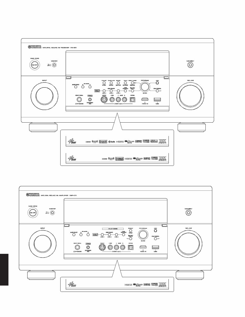
DSP-Z11 (R, T, K, B, G, E, L models)
■ FRONT PANELS
RX-Z11 (U, C models)
U model
C model
RX-Z11/DSP-Z11
5
RX-Z11/DSP-Z11
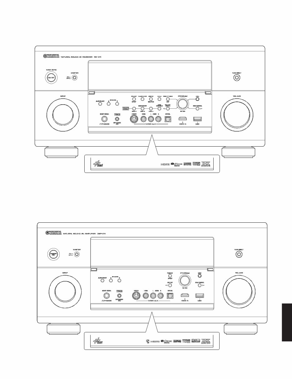
DSP-Z11 (J model)
RX-Z11 (A model)
RX-Z11/DSP-Z11
6
RX-Z11/DSP-Z11
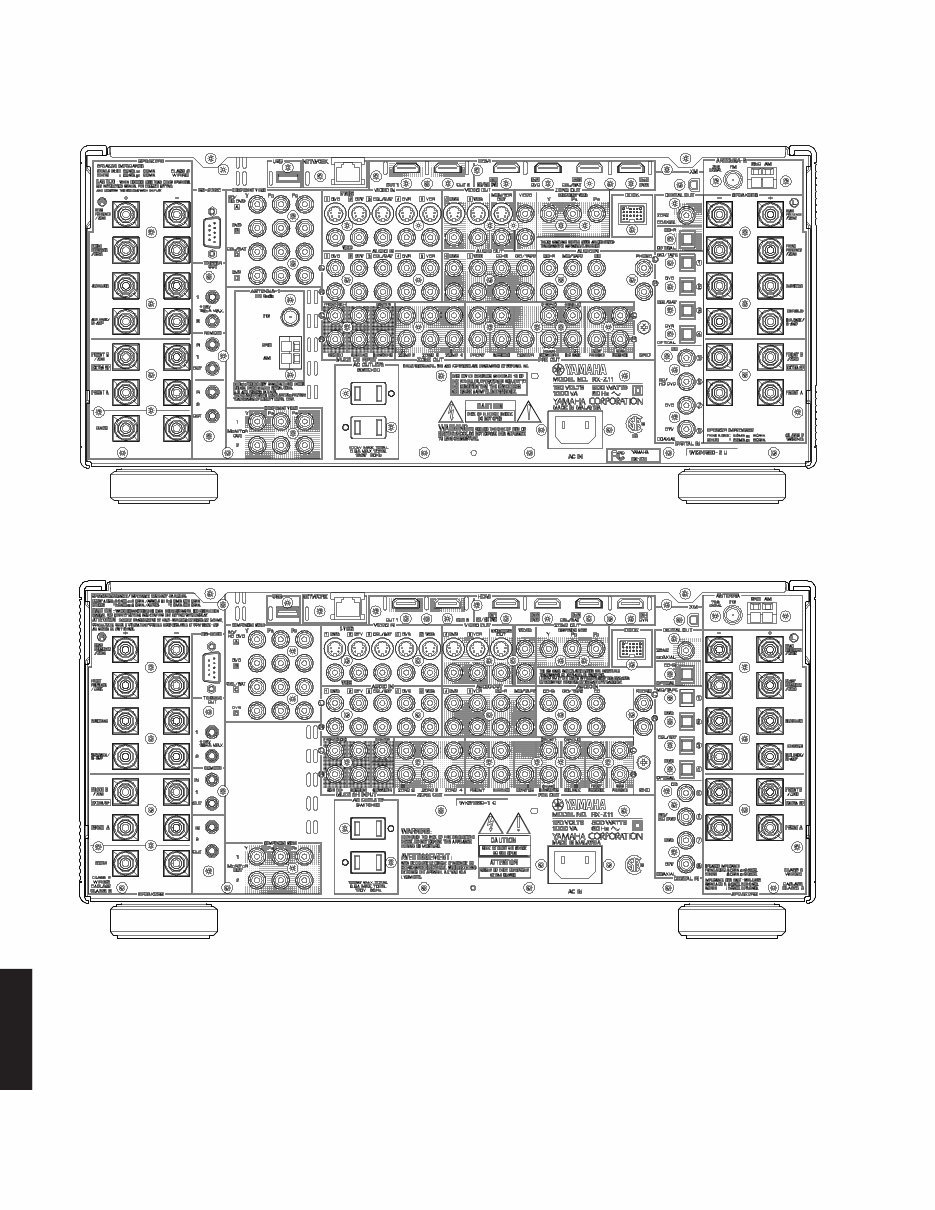
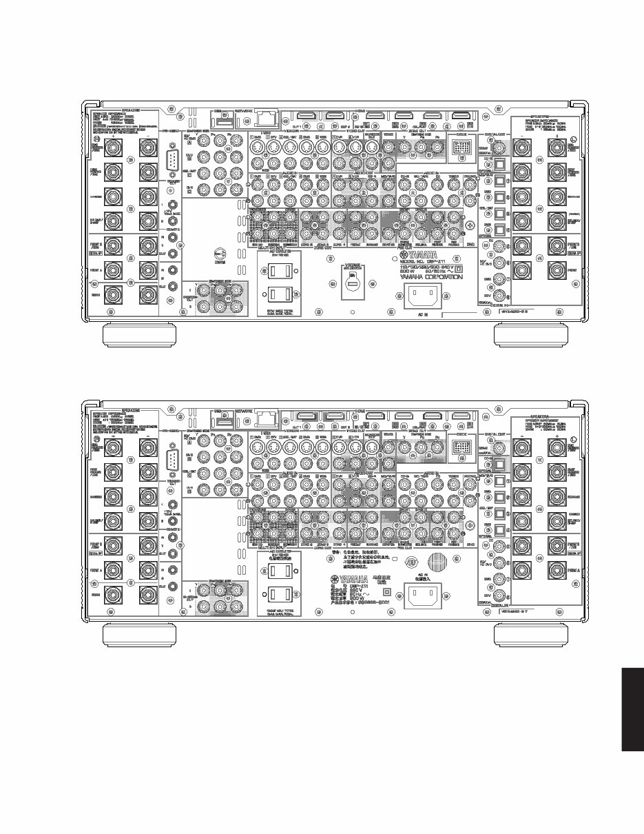
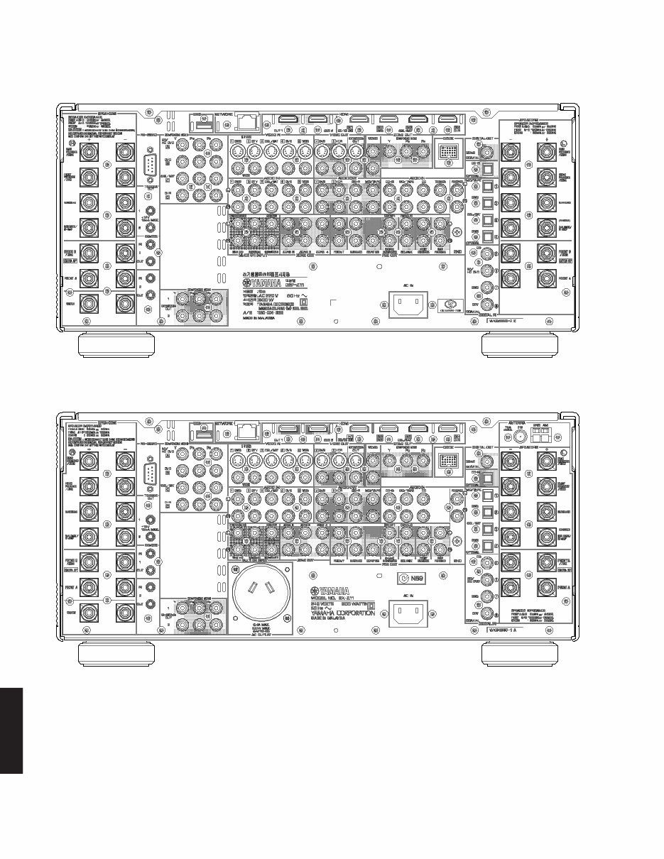
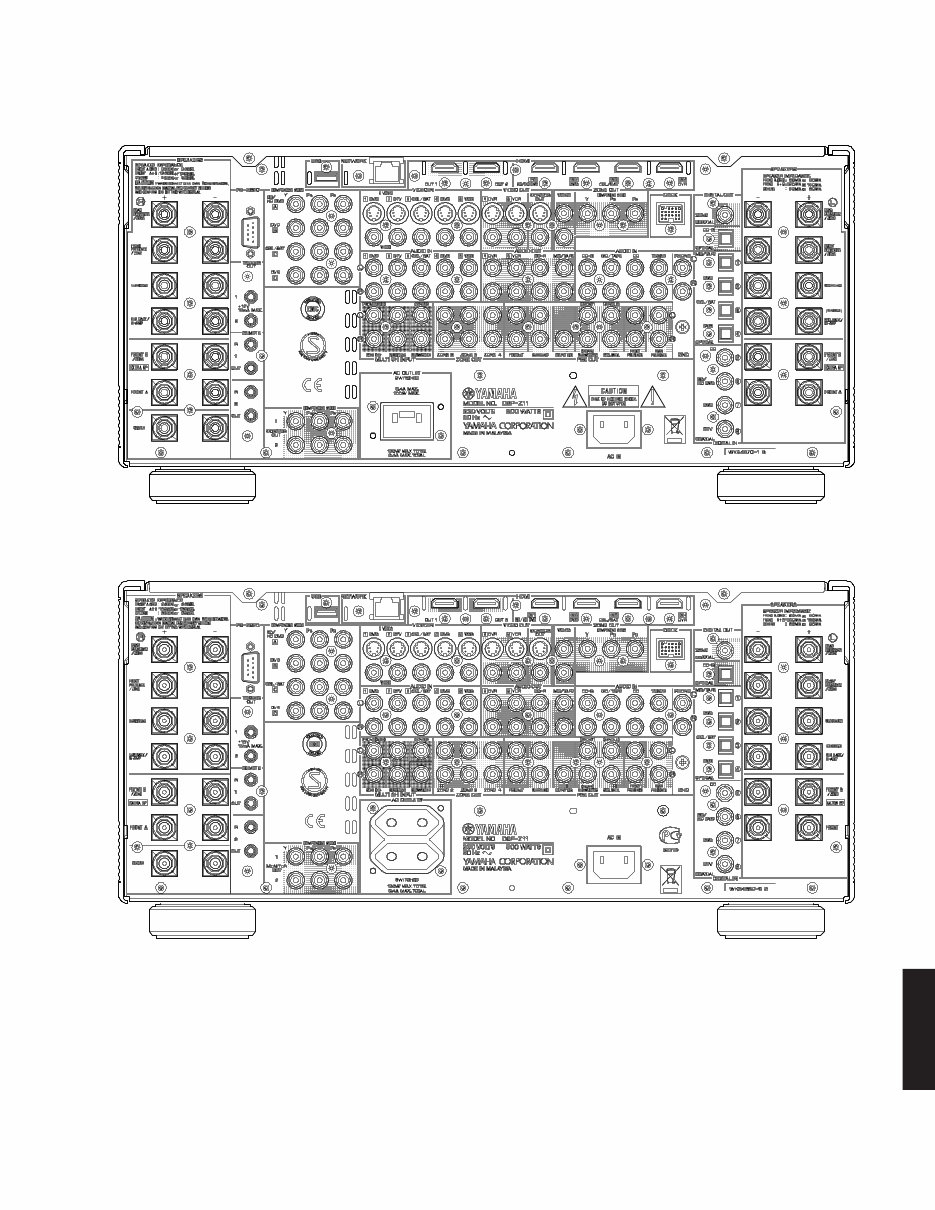
■ REAR PANELS
RX-Z11 (U model)
RX-Z11 (C model)
RX-Z11/DSP-Z11
7
RX-Z11/DSP-Z11
RX-Z11 (R model)
RX-Z11 (T model)
RX-Z11/DSP-Z11
8
RX-Z11/DSP-Z11
RX-Z11 (K model)
RX-Z11 (A model)
RX-Z11/DSP-Z11
9
RX-Z11/DSP-Z11
DSP-Z11 (B model)
DSP-Z11 (G, E models)
RX-Z11/DSP-Z11
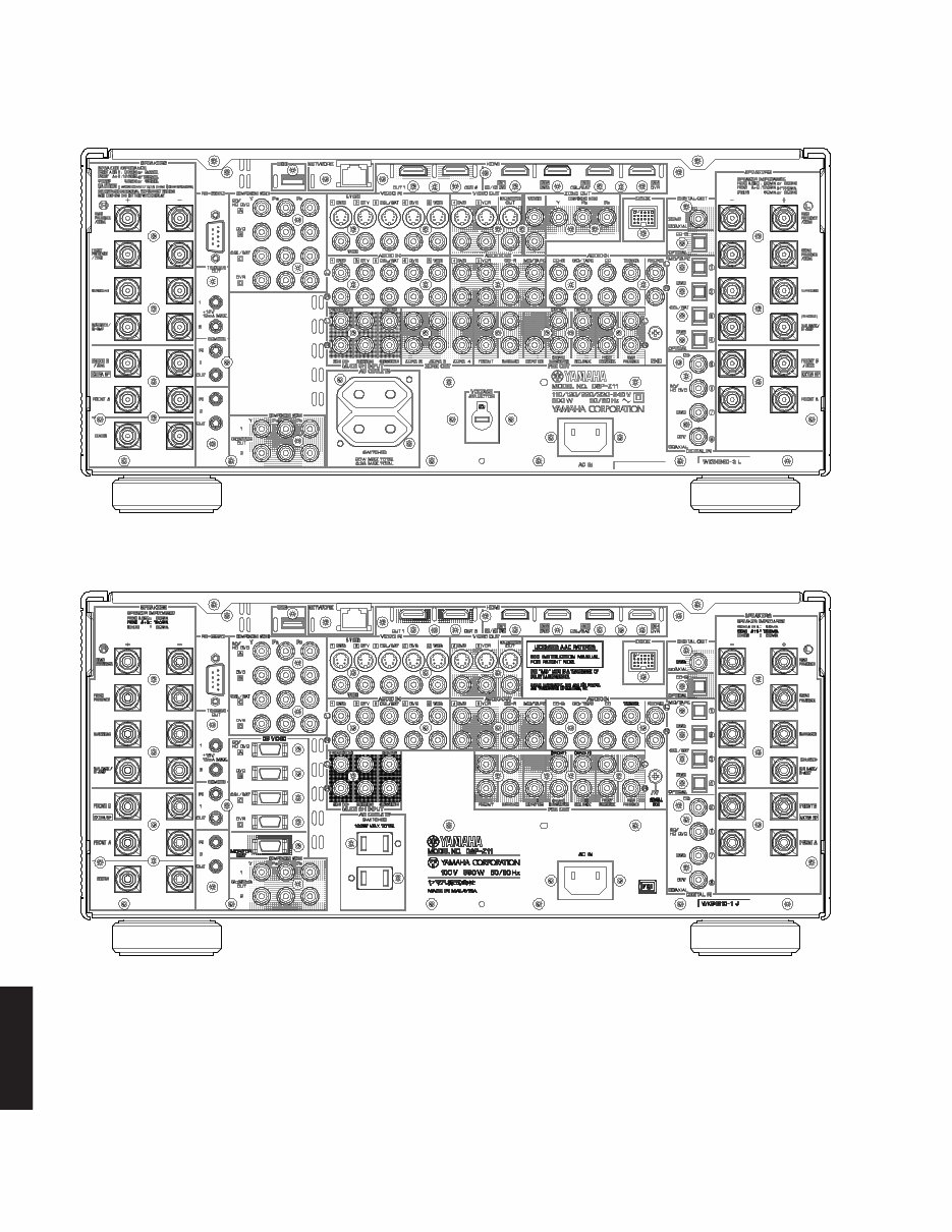
10
RX-Z11/DSP-Z11
DSP-Z11 (L model)
DSP-Z11 (J model)
You're Reading a Preview
What's Included?
Fast Download Speeds
Online & Offline Access
Access PDF Contents & Bookmarks
Full Search Facility
Print one or all pages of your manual
$31.99
$41.99
Viewed 55 Times Today


Secure transaction
What's Included?
Fast Download Speeds
Online & Offline Access
Access PDF Contents & Bookmarks
Full Search Facility
Print one or all pages of your manual
$31.99
$41.99
The Yamaha RX-Z1/DSP-AZ1 Service Manual is an essential resource for both professional mechanics and DIY enthusiasts. This comprehensive manual provides detailed information on the AV RECEIVER/AV AMPLIFIER, including impedance selector, front panels, rear panels, remote control, and internal view.
It covers a wide range of technical aspects such as disassembly procedures, self-diagnosis function (DIAG), amp adjustment, display data, IC data, block diagram, printed circuit board, pin connection diagram, schematic diagram, and parts list. With 164 pages of in-depth content, this manual is an invaluable tool for servicing and maintaining the Yamaha RX-Z1/DSP-AZ1 AV receiver/amplifier.
Language: English
Format: PDF
Platform: Windows and MAC


