

Sony STR-DH510 MULTI CHANNEL AV RECEIVER Service Manual
What's Included?
Fast Download Speeds
Online & Offline Access
Access PDF Contents & Bookmarks
Full Search Facility
Print one or all pages of your manual
SERVICE MANUAL
Published by Sony EMCS (Malaysia) PG Tec
Sony Corporation
Audio & Video Business Group
This receiver incorporates Dolby* Digital and Pro Logic Surround and the
DTS** Digital Surround System.
* Manufactured under license from Dolby Laboratories. Dolby, Pro Logic,
and the double-D symbol are trademarks of Dolby Laboratories.
** Manufactured under license under U.S. Patent #’s: 5,451,942; 5,956,674;
5,974,380; 5,978,762; 6,487,535 & other U.S. and worldwide patents
issued & pending. DTS and DTS Digital Surround are registered
trademarks and the DTS logos and Symbol are trademarks of DTS, Inc.
© 1996-2008 DTS, Inc. All Rights Reserved.
This receiver incorporates High-Definition Multimedia Interface (HDMI™)
technology. HDMI, the HDMI Logo, and High-Definition Multimedia
Interface are trademarks or registered trademarks of HDMI Licensing LLC
in the United States and other countries.
“x.v.Colour (x.v.Color)” and “x.v.Colour (x.v.Color)” logo are trademarks
of Sony Corporation.
“BRAVIA” is a trademark of Sony Corporation.
“PLAYSTATION” is a trademark of Sony Computer Entertainment Inc.
9-890-535-01
2010A80-1
© 2010.01
SPECIFICATIONS
MULTI CHANNEL AV RECEIVER
US Model
Canadian Model
Ver. 1.0 2010.01
STR-DH510
AUDIO POWER SPECIFICATIONS
POWER OUTPUT AND TOTAL HARMONIC DISTORTION:
(Models of area code US only)
With 8 ohm loads, both channels driven, from 20 – 20,000 Hz; rated 90
watts per channel minimum RMS power, with no more than 0.09% total
harmonic distortion from 250 milliwatts to rated output.
Amplifier section
Models of area code US
1)
Minimum RMS Output Power (8 ohms, 20 Hz – 20 kHz, THD 0.09%)
90 W + 90 W
Stereo Mode Output Power (8 ohms, 1 kHz, THD 1%)
100 W + 100 W
Surround Mode Output Power
2)
(8 ohms, 1 kHz, THD 10%)
130 W per channel
Models of area code CND
1)
Minimum RMS Output Power (8 ohms, 20 Hz – 20 kHz, THD 0.09%)
85 W + 85 W
Stereo Mode Output Power (8 ohms, 1 kHz, THD 1%)
100 W + 100 W
Surround Mode Output Power
2)
(8 ohms, 1 kHz, THD 10%)
130 W per channel
– Continued on next page –
http://www.xiaoyu163.com
http://www.xiaoyu163.com
STR-DH510
2
1)
Measured under the following conditions:
Area code Power requirements
US, CND 120 V AC, 60 Hz
2)
Reference power output for front, center and surround speakers.
Depending on the sound field settings and the source, there may be
no sound output.
Frequency response
Analog 10 Hz – 70 kHz,
+0.5/–2 dB (with sound
field and equalizer bypassed)
Input
Analog Sensitivity: 500 mV/
50 kohms
S/N
3)
: 96 dB
(A, 500 mV
4)
)
Digital (Coaxial) Impedance: 75 ohms
S/N: 100 dB
(A, 20 kHz LPF)
Digital (Optical) S/N: 100 dB
(A, 20 kHz LPF)
Output (analog)
AUDIO OUT Voltage: 500 mV/
10 kohms
SUBWOOFER Voltage: 2 V/1 kohm
Equalizer
Gain levels ±6 dB, 1 dB step
3)
INPUT SHORT (with sound field and equalizer bypassed).
4)
Weighted network, input level.
FM tuner section
Tuning range 87.5 MHz – 108.0 MHz
Antenna (aerial) FM wire antenna (aerial)
Antenna (aerial) terminals 75 ohms, unbalanced
Intermediate frequency 10.7 MHz
AM tuner section
Tuning range
Area code Tuning scale
10 kHz step 9 kHz step
US, CND 530 kHz
–
531 kHz
–
1,710 kHz 1,710 kHz
Antenna (aerial) Loop antenna (aerial)
Intermediate frequency 450 kHz
Video section
Inputs/Outputs
Video: 1 Vp-p, 75 ohms
COMPONENT VIDEO: Y: 1 Vp-p, 75 ohms
PB/CB: 0.7 Vp-p, 75 ohms
PR/CR: 0.7 Vp-p, 75 ohms
80 MHz HD Pass Through
General
Power requirements
Area code Power requirements
US, CND 120 V AC, 60 Hz
Power output (DIGITAL MEDIA PORT)
DC OUT: 5 V, 0.7 A MAX
Power consumption
Area code Power consumption
US, CND 230 W
Dimensions (width/height/depth) (Approx.)
430 mm × 157.5 mm × 322 mm
(17 in × 6 1/4 in × 12 3/4 in) including
projecting parts and controls
Mass (Approx.) 7.4 kg (16 lb 6 oz)
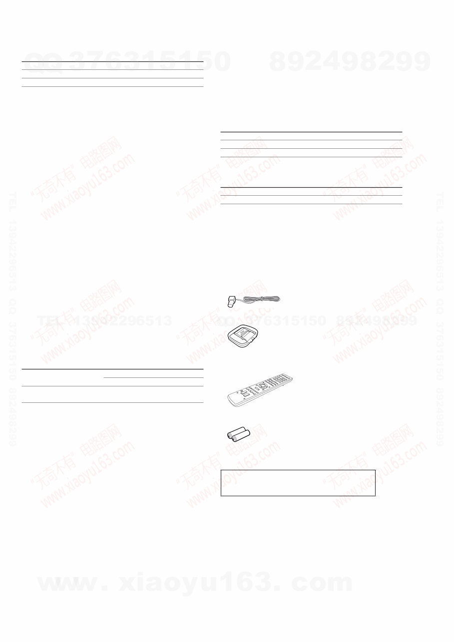
Supplied accessories
• Operating Instructions
• Quick Setup Guide
• FM wire antenna (aerial) (1)
• AM loop antenna (aerial) (1)
• Remote commander (1)
– RM-AAU071 (Models of area code US, CND only)
• R6 (size-AA) batteries (2)
Design and specifications are subject to change without notice.
• Standby power consumption: 0.3 W
• Halogenated flame retardants are not used in the certain
printed wiring boards.
Abbreviation
CND : Canadian model
http://www.xiaoyu163.com
http://www.xiaoyu163.com
STR-DH510
3
SAFETY CHECK-OUT
After correcting the original service problem, perform the follow-
ing safety check before releasing the set to the customer:
Check the antenna terminals, metal trim, “metallized” knobs,
screws, and all other exposed metal parts for AC leakage.
Check leakage as described below.
LEAKAGE TEST
The AC leakage from any exposed metal part to earth ground and
from all exposed metal parts to any exposed metal part having a
return to chassis, must not exceed 0.5 mA (500 microamperes.).
Leakage current can be measured by any one of three methods.
1. A commercial leakage tester, such as the Simpson 229 or RCA
WT-540A. Follow the manufacturers’ instructions to use these
instruments.
2. A battery-operated AC milliammeter. The Data Precision 245
digital multimeter is suitable for this job.
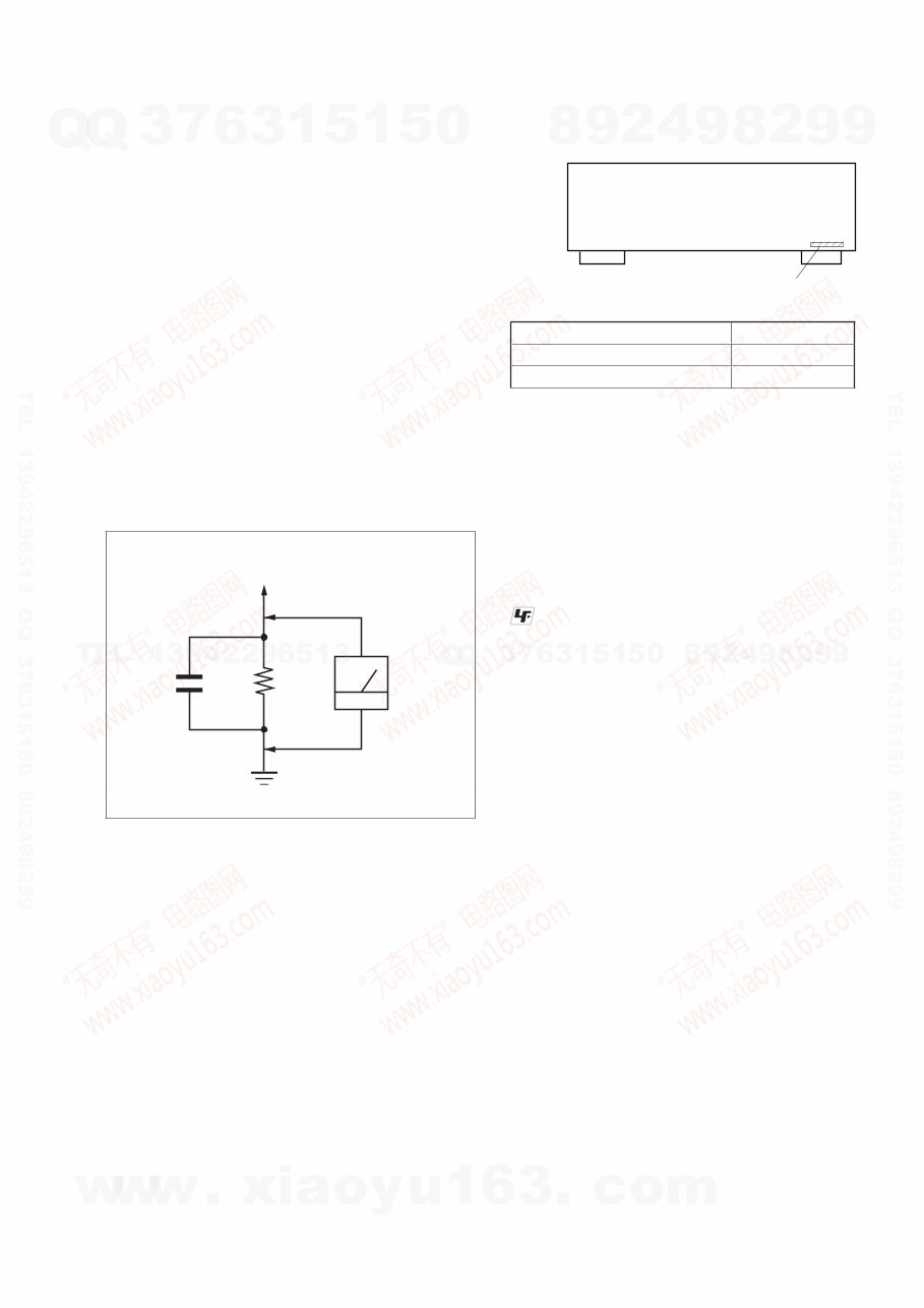
3. Measuring the voltage drop across a resistor by means of a
VOM or battery-operated AC voltmeter. The “limit” indication
is 0.75 V, so analog meters must have an accurate low-voltage
scale. The Simpson 250 and Sanwa SH-63Trd are examples
of a passive VOM that is suitable. Nearly all battery operated
digital multimeters that have a 2 V AC range are suitable. (See
Fig. A)
1.5 kΩ 0.15 μF
AC
voltmeter
(0.75 V)
To Exposed Metal
Parts on Set
Earth Ground
Fig. A. Using an AC voltmeter to check AC leakage.
SAFETY-RELATED COMPONENT WARNING!
COMPONENTS IDENTIFIED BY MARK 0 OR DOTTED LINE
WITH MARK 0 ON THE SCHEMATIC DIAGRAMS AND IN
THE PARTS LIST ARE CRITICAL TO SAFE OPERATION.
REPLACE THESE COMPONENTS WITH SONY PARTS
WHOSE PART NUMBERS APPEAR AS SHOWN IN THIS
MANUAL OR IN SUPPLEMENTS PUBLISHED BY SONY.
ATTENTION AU COMPOSANT AYANT RAPPORT
À LA SÉCURITÉ!
LES COMPOSANTS IDENTIFIÉS PAR UNE MARQUE 0 SUR
LES DIAGRAMMES SCHÉMATIQUES ET LA LISTE DES
PIÈCES SONT CRITIQUES POUR LA SÉCURITÉ DE FONC-
TIONNEMENT. NE REMPLACER CES COMPOSANTS QUE
PAR DES PIÈCES SONY DONT LES NUMÉROS SONT DON-
NÉS DANS CE MANUEL OU DANS LES SUPPLÉMENTS
PUBLIÉS PAR SONY.
MODEL IDENTIFICATION
–BACK PANEL–
Part No.
Model Part No.
US 4-164-299-0[]
Canadian 4-164-299-1[]
Notes on chip component replacement
• Never reuse a disconnected chip component.
• Notice that the minus side of a tantalum capacitor may be
damaged by heat.
UNLEADED SOLDER
Boards requiring use of unleaded solder are printed with the lead-
free mark (LF) indicating the solder contains no lead.
(Caution: Some printed circuit boards may not come printed with
the lead free mark due to their particular size)
: LEAD FREE MARK
Unleaded solder has the following characteristics.
• Unleaded solder melts at a temperature about 40 °C higher
than ordinary solder.
Ordinary soldering irons can be used but the iron tip has to be
applied to the solder joint for a slightly longer time.
Soldering irons using a temperature regulator should be set to
about 350 °C.
Caution: The printed pattern (copper foil) may peel away if
the heated tip is applied for too long, so be careful!
• Strong viscosity
Unleaded solder is more viscous (sticky, less prone to flow)
than ordinary solder so use caution not to let solder bridges
occur such as on IC pins, etc.
• Usable with ordinary solder
It is best to use only unleaded solder but unleaded solder may
also be added to ordinary solder.
NOTE OF REPLACING THE IC3500 AND IC3501 ON THE
HDMI BOARD
IC3500 and IC3501 on the HDMI board cannot exchange with
single. When these parts on the HDMI board are damaged,
exchange the entire mounted board.
http://www.xiaoyu163.com
http://www.xiaoyu163.com
STR-DH510
4
1. DISASSEMBLY
1-1. Case..................................................................................... 5
1-2. Back Panel Section ............................................................. 6
1-3. Front Panel Section ............................................................. 6
1-4. Digital Board....................................................................... 7
1-5. Main Board Section ............................................................ 7
2. TEST MODE ...................................................................... 8
3. FM TUNER CHECK .......................................................11
4. DIAGRAMS
4-1. Block Diagram – Tuner/Audio Section – .......................... 12
4-2. Block Diagram – Digital Section –.................................... 13
4-3. Block Diagram – Video Standby Section – ....................... 14
4-4. Block Diagram – HDMI PC Section – .............................. 15
4-5. Block Diagram – Key/Display Section – .......................... 16
4-6. Block Diagram – Power Key Section – ............................. 17
4-7. Printed Wiring Boards – Main Section – ........................... 19
4-8. Schematic Diagram – Main Section (1/3) – ...................... 20
4-9. Schematic Diagram – Main Section (2/3) – ...................... 21
4-10. Schematic Diagram – Main Section (3/3) – ...................... 22
4-11. Printed Wiring Board – Digital Section (1/2) – ................. 23
4-12. Printed Wiring Board – Digital Section (2/2) – ................. 24
4-13. Schematic Diagram – Digital Section (1/3) –.................... 25
4-14. Schematic Diagram – Digital Section (2/3) –.................... 26
4-15. Schematic Diagram – Digital Section (3/3) –.................... 27
4-16. Printed Wiring Board – Video Standby Section – ............. 28
4-17. Schematic Diagram – Video Standby Section – ................ 29
4-18. Printed Wiring Board – HDMI PC Section (1/2) – ........... 30
4-19. Printed Wiring Board – HDMI PC Section (2/2) – ........... 31
4-20. Schematic Diagram – HDMI PC Section (1/2) – .............. 32
4-21. Schematic Diagram – HDMI PC Section (2/2) – .............. 33
4-22. Printed Wiring Boards –
Headphone, Power Key Section – ..................................... 34
4-23. Schematic Diagram –
Headphone, Power Key Section – .................................... 34
4-24. Printed Wiring Board – Display Section – ........................ 35
4-25. Schematic Diagram – Display Section – ........................... 36
4-26. Printed Wiring Boards –
Temp-Sensor, Connection Section – ................................. 37
4-27. Schematic Diagram –
Temp-Sensor, Connection Section – ................................. 37
5. EXPLODED VIEWS
5-1. Case Section ...................................................................... 50
5-2. Front Panel Section............................................................ 51
5-3. Back Panel Section ............................................................ 52
5-4. Chassis Section .................................................................. 53
6. ELECTRICAL PARTS LIST ....................................... 54
TABLE OF CONTENTS
http://www.xiaoyu163.com
http://www.xiaoyu163.com
STR-DH510
5
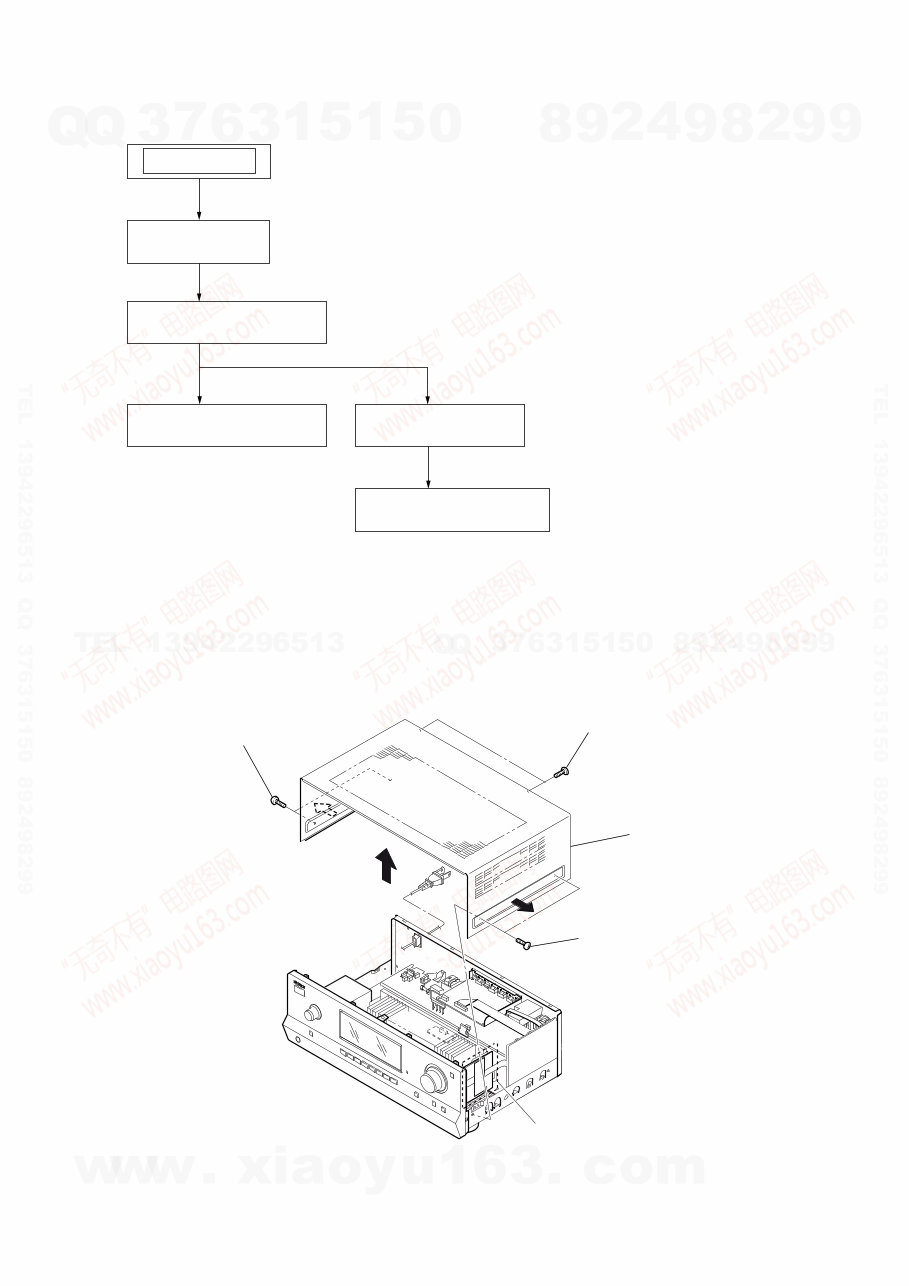
SECTION 1
DISASSEMBLY
Note: This set can be disassemble according to the following sequence.
1-4. DIGITAL BOARD
(Page 7)
1-5. MAIN BOARD SECTION
(Page 7)
1-1. CASE
(Page 5)
1-2. BACK PANEL SECTION
(Page 6)
1-3. FRONT PANEL SECTION
(Page 6)
SET
Note: Follow the disassembly procedure in the numerical order given.
1-1. CASE
1 two screws
3 two screws
(+BVTP 3 u 8)
4 case
2 two screws
(for Canadian model only)
http://www.xiaoyu163.com
http://www.xiaoyu163.com
STR-DH510
6
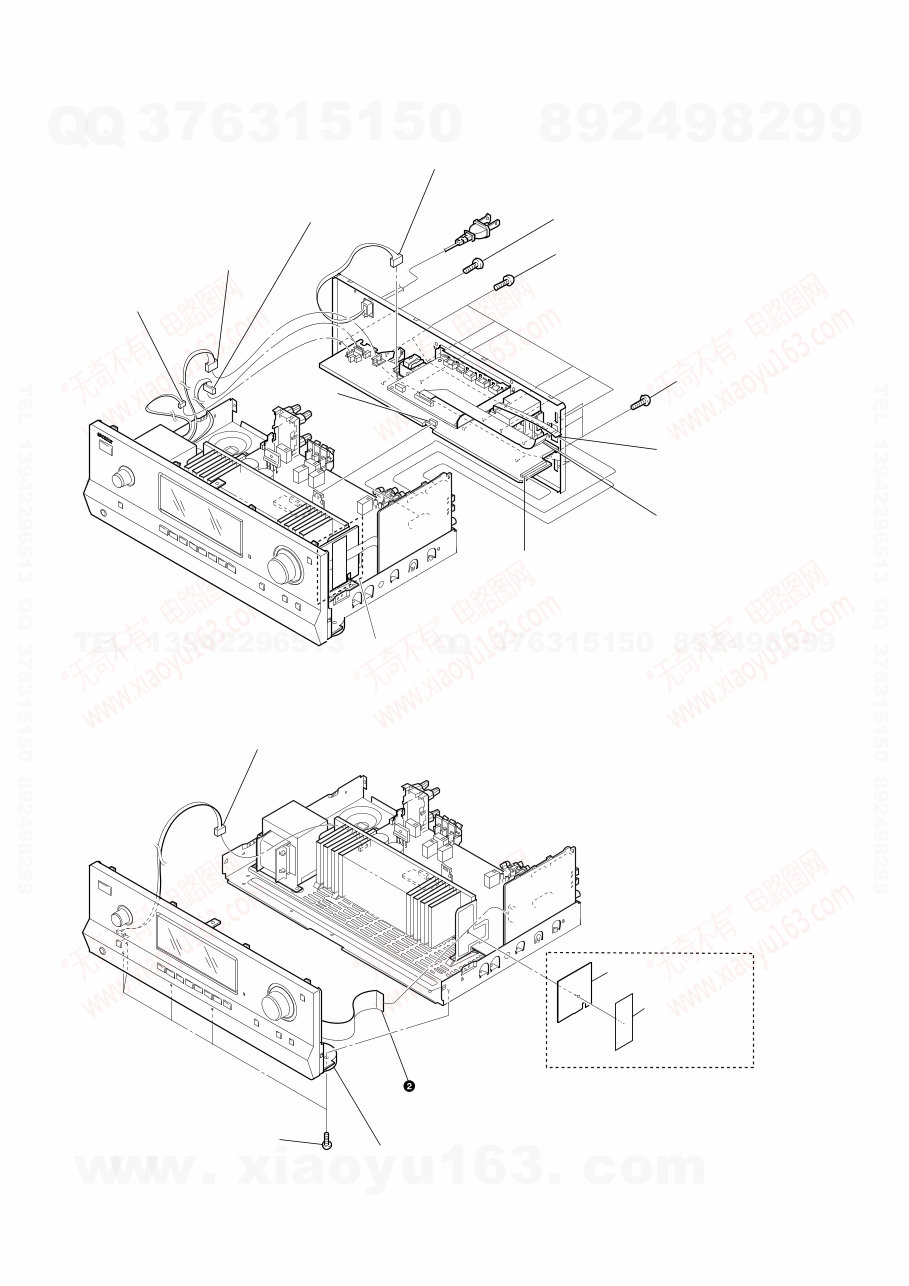
1-2. BACK PANEL SECTION
1-3. FRONT PANEL SECTION
4 CNP902 (2P)
2 CN906 (4P)
3 CN907 (3P)
5 CNS203 (6P)
6 wire (flat type) (9 core)
(CN2201)
7 wire (flat type) (19 core)
(CN2601)
8 CNS271 (17P)
9 five screws
(+BVTP 3 u 8)
0 six screws
(+BVTP 3 u 8)
qa three screws
(+BVTP 3 u 8)
1 CNP901 (2P)
(for Canadian model only)
1 CNP792 (4P)
3 five screws
(+BVTP 3 u 8)
4 front panel section
wire (flat type) (15 core)
(CN2106)
5 sheet, insulation
(for Canadian model only)
6 cushion, saranet
http://www.xiaoyu163.com
http://www.xiaoyu163.com
STR-DH510
7
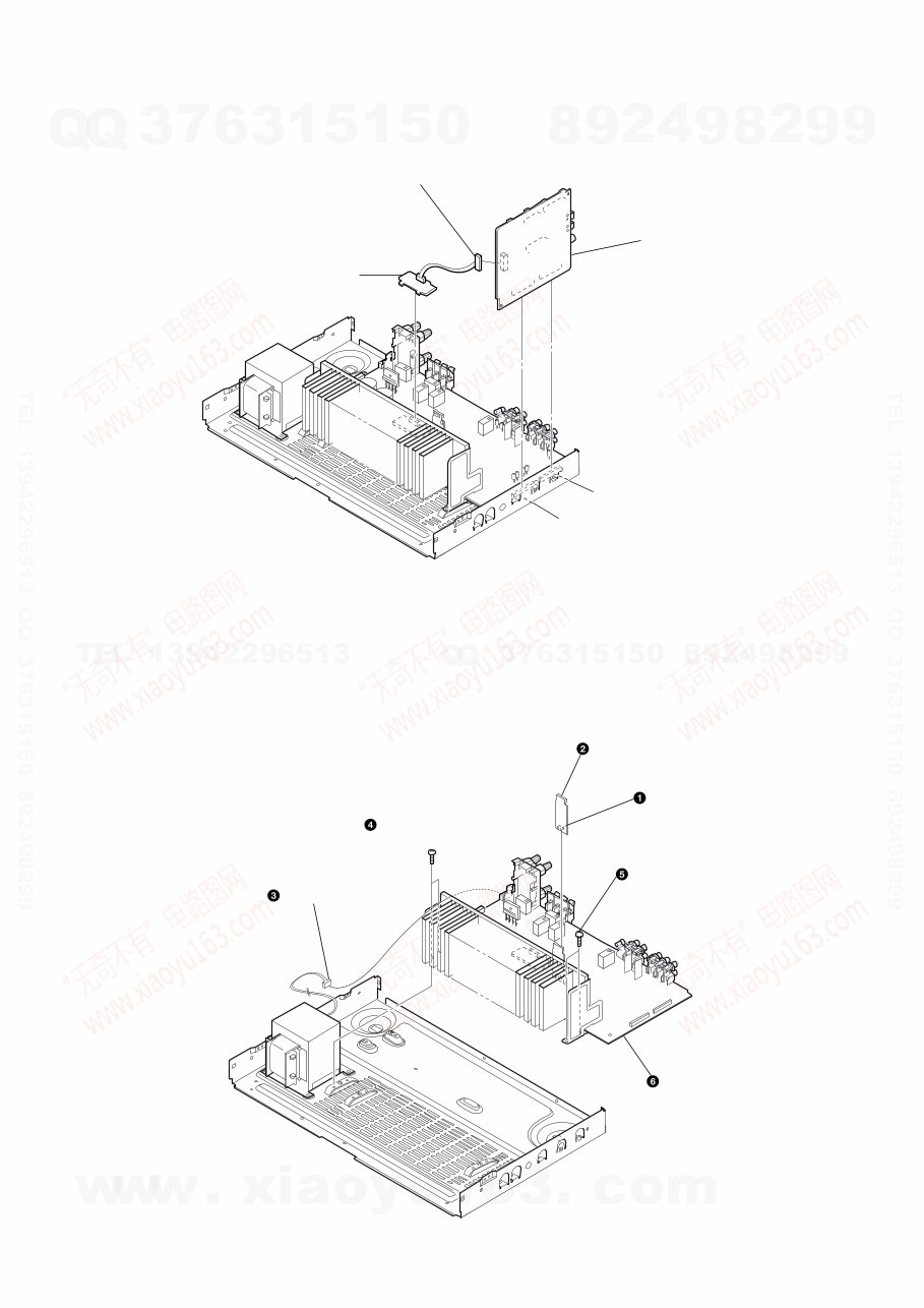
1-4. DIGITAL BOARD
1-5. MAIN BOARD SECTION
CNP410 (15P)
CNP412 (18P)
2
1 CN2501 (4P)
DIGITAL board
3 TEMP SENSOR board
CNP920 (5P)
two screws
(+BVTP 3 x 8 )
two screws
(+BVTP 3 x 8)
MAIN board section
CONNECTION board
CNS170 (6P)
http://www.xiaoyu163.com
http://www.xiaoyu163.com
STR-DH510
8
SECTION 2
TEST MODE
AM CHANNEL STEP 9 kHz/10 kHz SELECTION MODE
(US, Canadian model only)
* Either the 9 kHz step or 10 kHz step can be selected for the AM
channel step.
* Procedure:
Turn the [INPUT SELECTOR] control to set AM and press the
[?/1] button to turn off the main power.
1. While depressing the [TUNING MODE] button, press the
[?/1] button to turn on the main power.
2. Either the message “9K STEP” or “10K STEP” appears for a
moment and select the desired step.
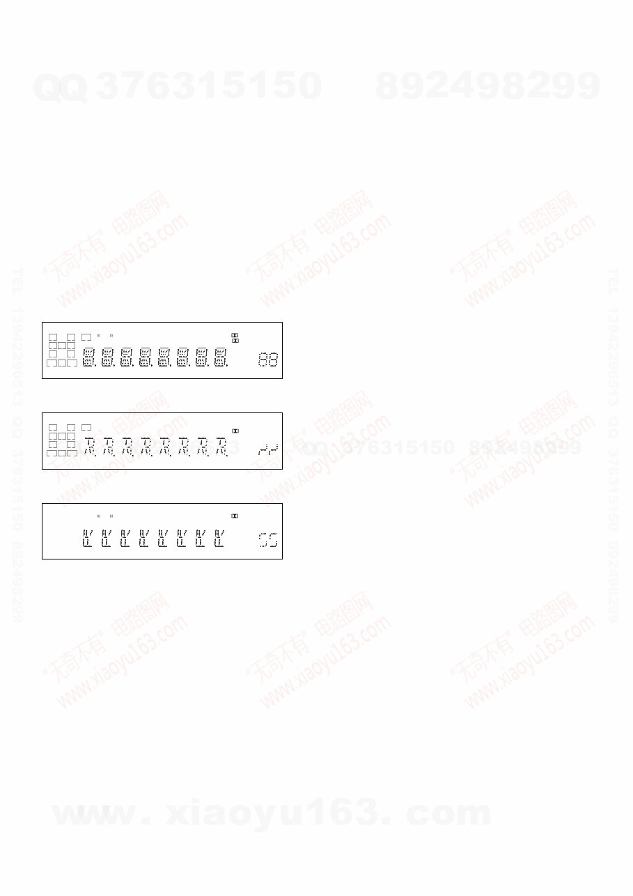
VACUUM FLUORESCENT DISPLAY TEST MODE
* All fluorescent segments are tested.
When this test is activated, all segments light on at the same time,
then each segment lights on one after another.
* Procedure:
While depressing the [TUNING +] and the [DIMMER] buttons
simultaneously, press the [?/1] button to turn on the main pow-
er.
1. ALL segments light on.
L C R
SL S SR
SBL SB SBR
LH RH SW
COAX OPT
HDMI LFE DTS -ES NEO:6 S-AIR 96/24
DTS-HD MSTR HI RES LBR LPCM
RDS
AAC
TrueHD
SLEEP
D.RANGE ST
D
PL II
+ EX
MHz ft.
k Hz m
x z
dB
2. Press the [DISPLAY] button, confirm display.
L C R
SL S SR
SBL SB SBR
LH RH SW
COAX OPT
HDMI LFE DTS -ES NEO:6 S-AIR 96/24
DTS-HD MSTR HI RES LBR LPCM
RDS
AAC
TrueHD
SLEEP
D.RANGE ST
D
PL II
+ EX
MHz ft.
k Hz m
x z
dB
3. Press the [DISPLAY] button, confirm display.
L C R
SL S SR
SBL SB SBR
LH RH SW
COAX OPT
HDMI LFE DTS -ES NEO:6 S-AIR 96/24
DTS-HD MSTR HI RES LBR LPCM
RDS
AAC
TrueHD
SLEEP
D.RANGE ST
D
PL II
+ EX
MHz ft.
k Hz m
x z
dB
4. Press the [DISPLAY] button, all segments light off.
SOUND FIELD CLEAR MODE
* The preset sound field is cleared when this mode is activated.
Use this mode before returning the product to clients upon com-
pletion of repair.
* Procedure:
1. While depressing the [MUSIC] button, press the [?/1] button
to turn on the main power.
2. The message “S.F. CLEAR” appears for a moment and initial-
ization is performed.
SOFTWARE VERSION CHECK MODE
* The software version is displayed.
* Procedure:
1. While depressing the [TUNING MODE] and the [DISPLAY]
buttons simultaneously, press the [?/1] button to turn on the
main power.
2. The model name, destination and the software version are
displayed for a moment.
KEY CHECK MODE
* Button check
* Procedure:
1. While depressing the [TUNING +] and the [MUTING] but-
tons simultaneously, press the [?/1] button to turn on the main
power.
2. The message “REST 12” appears.
3. Every pressing of any button other than the [?/1] counts down
the buttons. The buttons which are already counted once are
not counted again. When all buttons are pressed “REST 00”
appears.
SWAP ALL MODE
* The signal will be swap to all channel so that all speaker will
have sound output.
* Procedure:
1. While depressing the [TUNING MODE] and the [MOVIE]
buttons simultaneously, press the power [?/1] button to turn
on the main power.
2. “SWAP.MODE” appears. (No change while displayed.)
SHIPMENT MODE
* All preset contents are reset to the default setting.
* Procedure:
1. While depressing the [TUNING MODE] and the [DIMMER]
buttons simultaneously, press the power [?/1] button to turn
on the main power.
2. The message “CLEARING” appears.
3. After a few seconds, “CLEARED” appears and switch off the
set.
PROTECTOR AUTO OFF
* To disable auto off after protector occur.
* Procedure:
1. While depressing the [INPUT MODE] and the [A.F.D.] but-
tons simultaneously, press the power [?/1] button to turn on
the main power.
2. “PROTECT” appears.
http://www.xiaoyu163.com
http://www.xiaoyu163.com
STR-DH510
9
HISTORY MODE
* The state that the set is used is memorized.
* Procedure:
1. While depressing the [INPUT MODE] and the [MUSIC]
buttons simultaneously, press the [?/1] button to turn on the
main power.
2. “HISTORY” appears.
3. Each time the [↑] / [↓] buttons on the remote commander is
pressed, the item is switched in order as follows.
Items
Protector Count COUNT XX
Total single power on time XXXXXHXX 01
Sound Field SND FLD
Input function FUNCTION
Input Mode INP MODE
Digital Select DIG IN
Stream information STREAM
Signal configuration CO XXXXX
Headphones HP XXX
Volume VOL XX
Bass Setting BASS XXX
Treble Setting TREB XXX
Level FL/FR F XXXXXX
Level SL/SR S XXXXXX
Level CT/SW CW XXXXXX
Level SBL/SBR B XXXXXX
Total power on time OH X 02
Muting Status MUTE XXX
Power on counter
(Rebox test mode)
REBX. X
Protector Type PROT XXXX
Temperature when protect TEM XXXX
DCAC TEST MODE
Procedure:
1. While pressing [INPUT MODE] and the [MOVIE] buttons,
press the [?/1] button to turn on the main power.
2. The message “DCAC FTM” appears.
SOURCE : normal mode
MIC IN : mode that output audio from mic input.
3. Afterward, press the [DISPLAY] to start DCAC factory test
mode.
INITIALIZE MODE
All preset contents are cleared when this mode is activated. Use
this mode before returning the product to clients upon completion
of repair.
Procedure:
1. While pressing the [TUNING MODE] and [MUTING] but-
tons, press the [?/1] button to turn on the main power.
2. The message “CLEARING” appears and the memories are re-
set to the default values.
3. When done, the message “CLEARED” appears.
COMMAND MODE CHANGE MODE
The command mode of the remote-commander which this set re-
ceives can be changed.
Procedure:
1. While pressing the [INPUT MODE] and [2CH/A.DIRECT]
buttons, press the [?/1] button to turn on the main power.
2. Either the message “C.MODE.AV1” or “C.MODE.AV2” ap-
pears. Select the desired mode.
USER INITIALIZE
Procedure:
1. Hold the [?/1] for 5 seconds.
2. The message “CLEARING” appears on the display.
3. After a few seconds, “CLEARED” appears.
http://www.xiaoyu163.com
http://www.xiaoyu163.com
STR-DH510
10
DMPORT MODE
* All preset contents are cleared when this mode is activated. Use
this mode before returning the product to clients upon comple-
tion of repair.
* Procedure:
1. Connect the DMPORT check jig (P/N: J-2501-309-A) with
the DMPORT Jack (J2901) on the MICOM board.
2. While pressing the [TUNING MODE] and [MUSIC] buttons,
press the [?/1] button to turn on the main power.
3. The message “DMPORT T.” and “DMPORTOK” appears on
the fluorescent indicator tube and enter the digital media port
test mode. (Confirmation of communication line). When
“NO DET”, “UART NG” and “UART TO” are displayed on
the fluorescent indicator tube, confirm the connection of the
DMPORT check jig, and enter the mode again. Each time the
[>] button on the remote commander is pressed, the con-
nect check and adaptor version check are switched. Press the
[.] button on the remote commander, connected confirma-
tion of the DMPORT check jig is done again.
4. To a pin jack of the DMPORT check jig input information
relevant to audio signal (sine-wave 1.0V rms) and composite
video signal (white 100% 1.0Vp-p, color bar, etc).
5. Confirm the output of speakers and monitor TV. (Confirma-
tion of analog signal).
6. To release from this mode, press the [x] button on the remote
commander.
color
pattern
generator
DMPORT
check jig
(Part No.:
J-2501-309-A)
MICOM board
J2901
set
TV
monitor
FL/FR
speaker
MAIN board
TB601
J001
AF
oscillator
http://www.xiaoyu163.com
http://www.xiaoyu163.com
You're Reading a Preview
What's Included?
Fast Download Speeds
Online & Offline Access
Access PDF Contents & Bookmarks
Full Search Facility
Print one or all pages of your manual
$31.99
$41.99
Viewed 60 Times Today


Secure transaction
What's Included?
Fast Download Speeds
Online & Offline Access
Access PDF Contents & Bookmarks
Full Search Facility
Print one or all pages of your manual
$31.99
$41.99
This service manual for the Sony STR-DH510 MULTI CHANNEL AV RECEIVER provides detailed disassembly instructions, test mode procedures, FM tuner checks, diagrams, exploded views, and an electrical parts list. It is available in English and can be accessed on both Windows and Mac platforms.
The manual is a valuable resource for professional mechanics and DIY enthusiasts alike, offering essential technical information for repair and maintenance.


