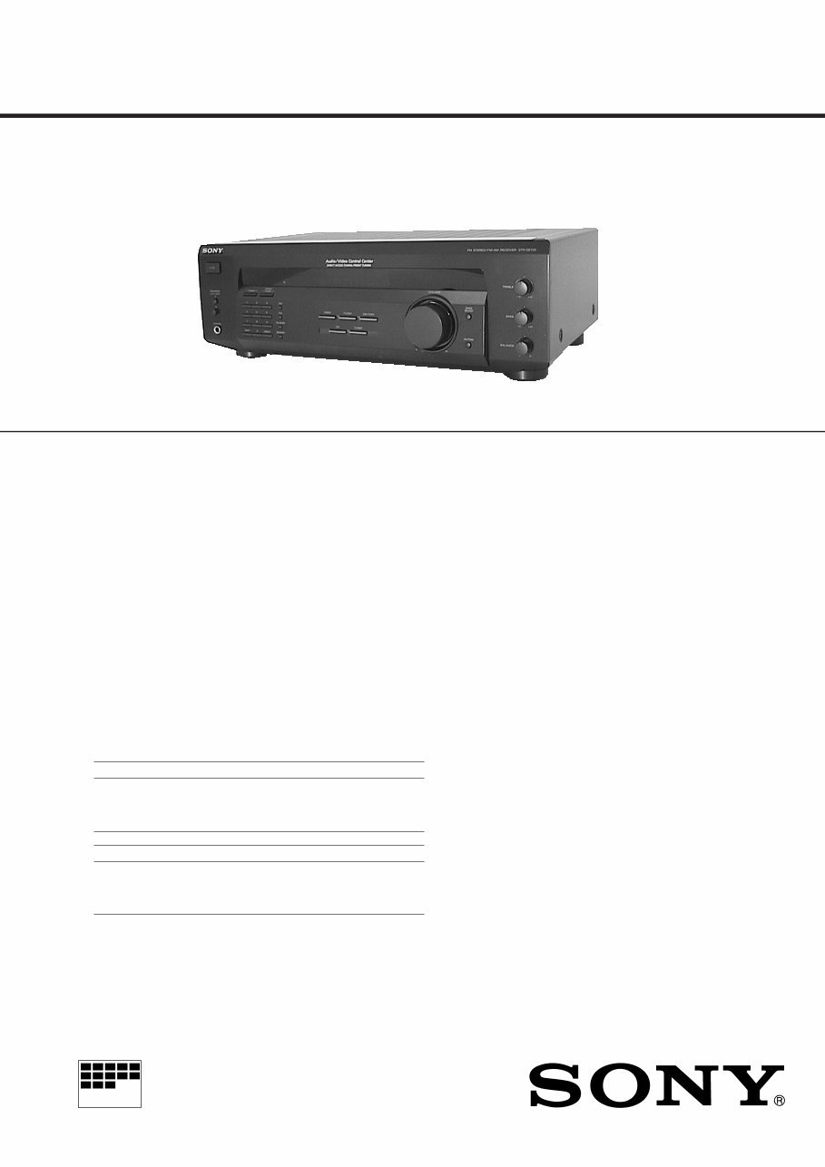
MICROFILM SERVICE MANUAL FM STEREO/FM-AM-RECEIVER US Model AEP Model UK Model STR-DE135 SPECIFICATIONS Photo: US model Audio power specifications (US model) POWER OUTPUT AND TOTAL HARMONIC DISTORTION With 8-ohm load, both channels driven, from 20 – 20,000 Hz, rated 100 watts per channel minimum RMS power, with no more than 0.09 % total harmonic distortion from 250 milli- watts to rated output. Amplifier section Stereo mode (8 ohms at 20 Hz – 20 kHz less than 0.09 % total harmonic distortion) 100 W + 100 W (US model) (DIN 1 kHz, 4 ohms) 60 W + 60 W (AEP, UK models) Frequency response TV/SAT, CD, MD/TAPE, VIDEO (US model) TV/LD, CD, MD/TAPE, VIDEO (AEP, UK models) 10 Hz – 50 Hz ± 1 dB Inputs Sensitivity Impedance S/N CD, MD/TAPE, 150 mV 50 78 dB TV/SAT, kilohms VIDEO (US model) Sensitivity Impedance S/N CD, MD/TAPE, 150 mV 50 78 dB TV/LD, kilohms VIDEO (AEP, UK models) outputs MD/TAPE REC OUT: Voltage: 150 mV, impedance: 10 kilohms VIDEO AUDIO OUT: Voltage: 150 mV, impedance: 10 kilohms PHONES: Accepts low and high impedance headphones Muting Full mute BASS BOOST + 10 dB at 70 Hz TONE ± 8 dB at 100 Hz and 10 kHz Tuner Section FM stereo, FM/AM superheterodyne tuner FM tuner section Tuning range 87.5 – 108.0 MHz Antenna terminals 75 ohms, unbalanced Intermediate frequency 10.7 MHz Sensitivity Mono: 18.3 dBf, 4.5 μV Stereo: 38.3 dBf, 45 μV (US model) Mono: 18.3 dBf, 2.2 μV/75 ohms Stereo: 38.3 dBf, 22.5 μV/75 ohms (AEP, UK models) Usable sensitivity 11.2 dBf, 2 μV (IHF) (US model) 11.2 dBf, 1 μV/75 ohms (IHF) (AEP, UK models) S/N Mono: 76 dB Stereo: 70 dB Harmonic distortion at 1 kHz Mono: 0.3 % Stereo: 0.5 % Separation 45 dB at 1kHz Frequency response 30 Hz – 15 kHz dB Selectivity 60 dB at 400 kHz AM tuner section Tuning range 10 kHz interval* 530 – 1710 kHz 9 kHz interval 531 – 1710 kHz (US model) 531 – 1602 kHz (AEP, UK models) +0.5 –2 – Continued on next page –
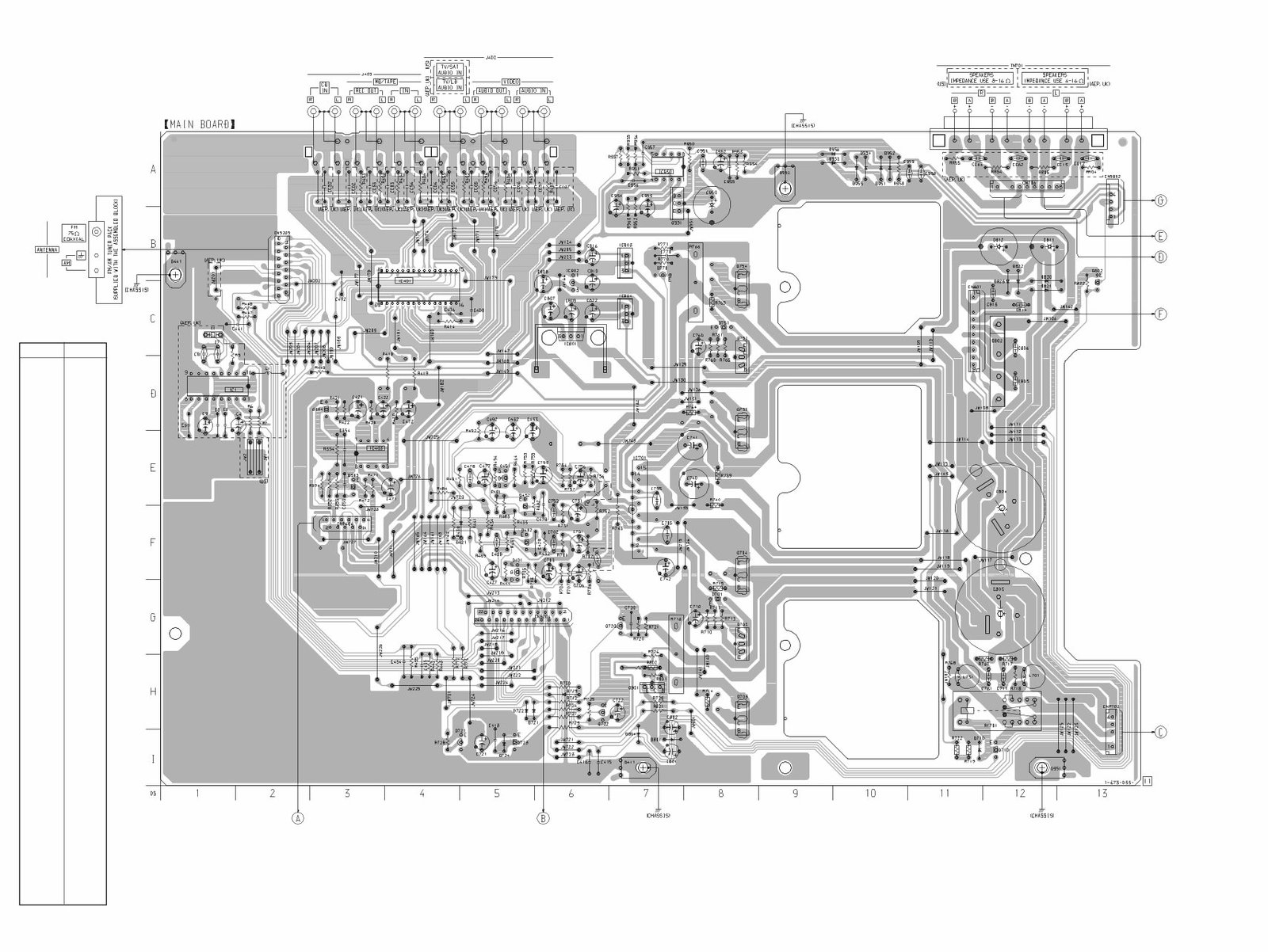
– 2 – TABLE OF CONTENTS 1. SERVICING NOTES ............................................... 3 2. GENERAL ................................................................... 4 3. DISASSEMBLY ......................................................... 5 4. TEST MODE ............................................................... 7 5. DIAGRAMS 5-1. Note for Printed Wiring Boards and Schematic Diagrams ....................................................... 9 5-2. Printed Wiring Board – MAIN Board – ........................ 11 5-3. Schematic Diagram – MAIN Board (1/2) – .................. 13 5-4. Printed Wiring Boards – DISPLAY Board/KEY Board/VOLUME Board/ TONE Board/POWER SWITCH Board – ................... 15 5-5. Schematic Diagram – PANEL Section – ......................................................... 19 5-6. Printed Wiring Boards – PANEL Section – ......................................................... 23 5-7. Schematic Diagram – MAIN Board (2/2)/SPK SWITCH Board/ SECONDARY Board/PRIMARY Board/ STANDBY TRANS Board – ....................................... 25 5-8. IC Pin Function Description ........................................... 26 6. EXPLODED VIEWS ................................................ 28 7. ELECTRICAL PARTS LIST ............................... 31 SAFETY-RELATED COMPONENT WARNING!! COMPONENTS IDENTIFIED BY MARK ! OR DOTTED LINE WITH MARK ! ON THE SCHEMATIC DIAGRAMS AND IN THE PARTS LIST ARE CRITICAL TO SAFE OPERATION. REPLACE THESE COMPONENTS WITH SONY PARTS WHOSE PART NUMBERS APPEAR AS SHOWN IN THIS MANUAL OR IN SUPPLEMENTS PUB- LISHED BY SONY. Antenna Loop antenna Intermediate frequency 450 kHz Usable sensitivity 50 dB/m (at 1,000 kHz) S/N 54 dB (at 50 mV/m) Harmonic distortion 0.5 % (50 mV/m, 400Hz) Selectivity At 10 kHz: 40 dB At 9 kHz: 35 dB (US model) 35 dB (AEP, UK models) * You can change the AM tuning interval between 9 kHz and 10kHz. After tuning in any AM station, turn off the receiver. Hold down the PRESET TUNING + button and press the 1/u (power) button. All pre- set stations will be erased when you change the interval. To reset the interval, repeat the procedure. (US model) General System Tuner section: PLL quartz-locked digital synthesizer system Preamplifier section: Low-noise NF type equalizer Power amplifier section: Pure-complementary SEPP Power requirements 120 V AC, 60 Hz (US model) 230 V AC, 50/60 Hz (AEP, UK models) Power consumption 155 W (US model) 135 W (AEP, UK models) AC outlets 1 switched, total 120 W/1A Max (US, UK models) switch 100 W max (AEP model) Dimensions 430 × 144 × 306 mm (17 × 5 6 /8 × 12 4 /8 inches) Mass (Approx.) 8.1 kg (17 lb 13 oz) (US model) 6.7 kg (AEP, UK models) Supplied accessories FM wire antenna (1) AM loop antenna (1) Remote commander (remote) (1) Size AA (R6) batteries (2) Specifications indicated are measured at 230 V AC, 50Hz. (AEP, UK models) Design and specifications are subject to change without notice.
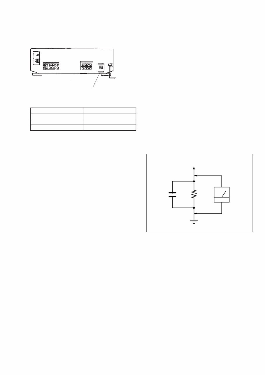
– 3 – SECTION 1 SERVICING NOTES MODEL IDENTIFICATION – Rear view – PART No. MODEL PART No. US model 4-216-802-0π AEP model 4-216-802-1π UK model 4-216-802-2π SAFETY CHECK-OUT After correcting the original service problem, perform the follow- ing safety check before releasing the set to the customer: Check the antenna terminals, metal trim, “metallized” knobs, screws, and all other exposed metal parts for AC leakage. Check leakage as described below. LEAKAGE TEST The AC leakage from any exposed metal part to earth ground and from all exposed metal parts to any exposed metal part having a return to chassis, must not exceed 0.5 mA (500 microampers.). Leakage current can be measured by any one of three methods. 1. A commercial leakage tester, such as the Simpson 229 or RCA WT-540A. Follow the manufacturers’ instructions to use these instruments. 2. A battery-operated AC milliammeter. The Data Precision 245 digital multimeter is suitable for this job. 3. Measuring the voltage drop across a resistor by means of a VOM or battery-operated AC voltmeter. The “limit” indica- tion is 0.75 V, so analog meters must have an accurate low- voltage scale. The Simpson 250 and Sanwa SH-63Trd are ex- amples of a passive VOM that is suitable. Nearly all battery operated digital multimeters that have a 2 V AC range are suit- able. (See Fig. A) Fig. A. Using an AC voltmeter to check AC leakage. 1.5 k Ω 0.15 μF AC voltmeter (0.75 V) To Exposed Metal Parts on Set Earth Ground
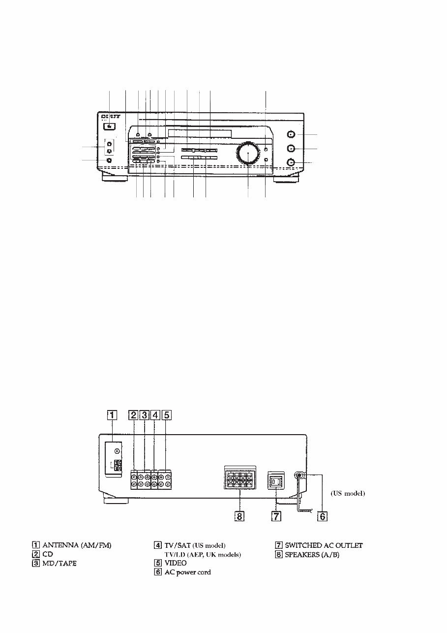
– 4 – SECTION 2 GENERAL 1 I/u button 2 TUNING +, – buttons (US model) TUNING/CHAR +, – buttons (AEP, UK models) 3 NAME button (AEP, UK models) 4 PRESET/TUNING +, – buttons (US model) PRESET/PTY SELECT +, – buttons (AEP, UK models) 5 DISPLAY button (AEP, UK models) 6 RDS PTY button (AEP, UK models) 7 AM button (US model) RDS EON button (AEP, UK models) Location of controls • Front view – 8 FM button (US model) FM/AM button (AEP, UK models) 9 VIDEO button 0 TV/SAT button (US model) TV/LD button (AEP, UK models) !¡ MD/TAPE button !™ BASS BOOST button and indicator !£ SPEAKERS A, B ON/OFF buttons !¢ PHONES jack !∞ SHIFT button !§ Numeric buttons !¶ DIRECT button !• MEMORY button (US model) MEMORY/ENTER button (AEP, UK models) !ª FM MODE button @º TUNER button @¡ CD button @™ VOLUME control @£ MUTING button and indicator @¢ TREBLE control @∞ BASS control @§ BALANCE control 345 1 2 67 !∞ 890 !¡ !™ !£ !¢ !§!¶ !• !ª @º @¡ @™ @£ @¢ @∞ @§ • Rear view –
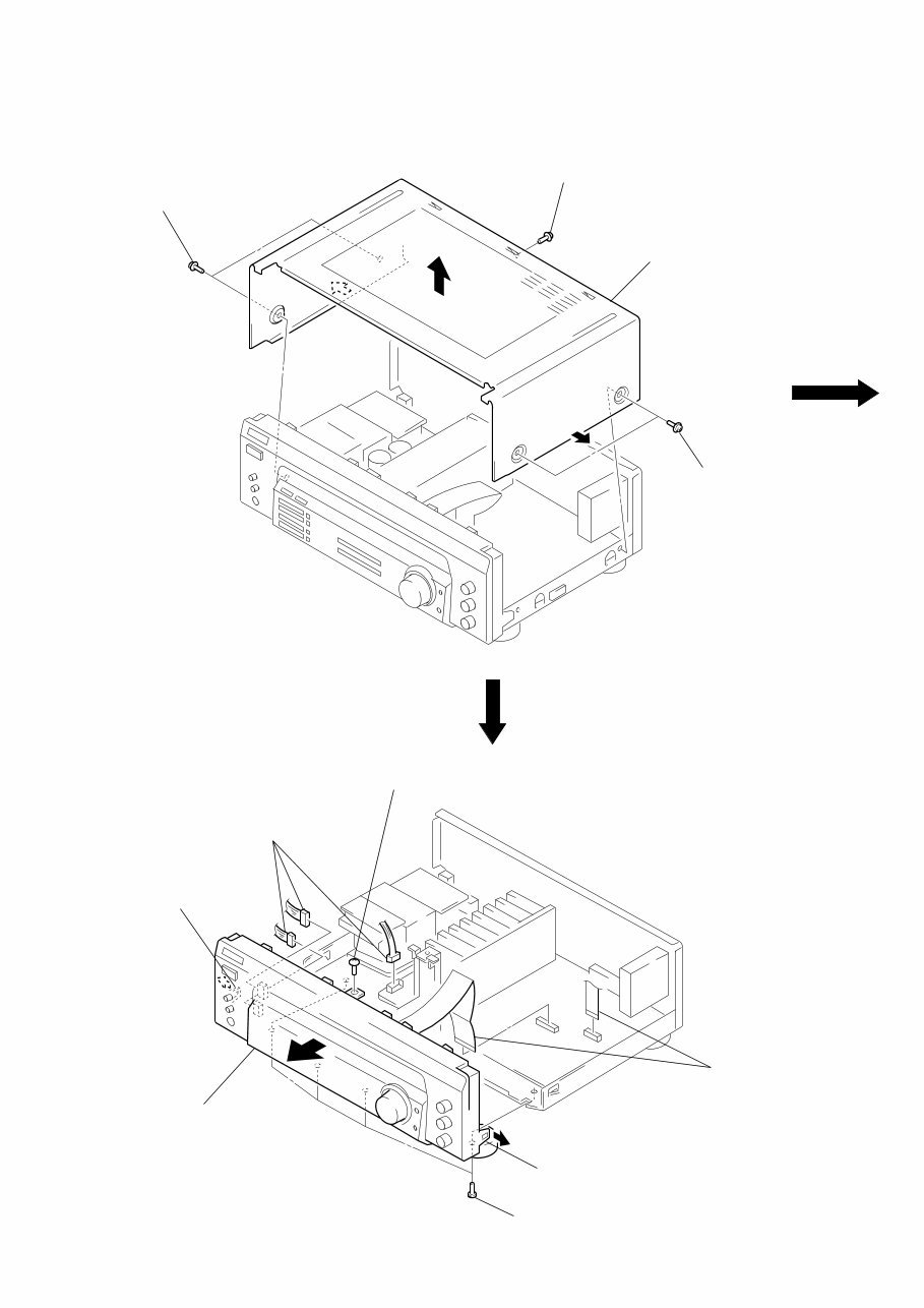
– 5 – CASE FRONT PANEL SECTION Note: Follow the disassembly procedure in the numerical order given. SECTION 3 DISASSEMBLY 1 two tapping screws 1 tapping screw 2 case 1 two tapping screws 2 three connectors (CNP702 – 704) 3 screw (BVTP3 × 8) 4 claw 5 front panel section 3 four screws (BVTP3 × 8) 4 claw 1 two flat wires (CNS204, CNP404)
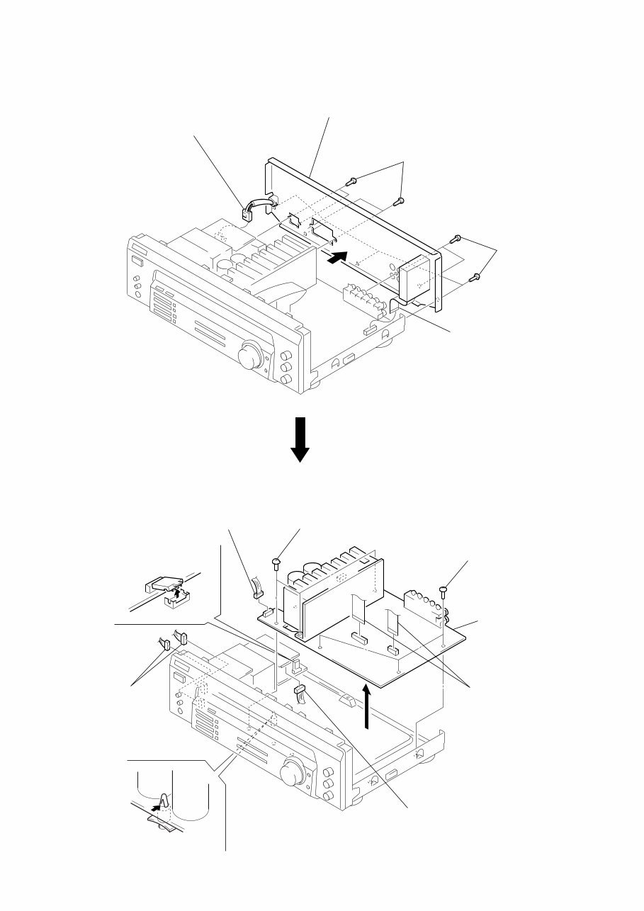
– 6 – REAR PANEL SECTION MAIN BOARD 2 connector (CNP901) 4 rear panel section 3 four screws (BVTP3 × 8) 3 six screws (BVTP3 × 8) 1 flat wire (CNS205) 2 connector (CNS802) 2 two connectors (CNP703, 704) 4 PC board holder 2 connector (CNP801) 1 two flat wires (CNS204, CNP404) 5 MAIN board 3 three screws (BVTP3 × 8) 3 three screws (BVTP3 × 8) 2 connector (CNP702)
– 7 – SECTION 4 TEST MODE Fluorescent Indicator Tube Test Mode All fluorescent segments are tested. When this test is activated, all segments turn on at the same time, then each segment turns on one after another. Procedure: 1. While pressing two buttons of [TV/SAT] (US model)* and [DIRECT] simultaneously, press the 1/u button to turn the power ON. 2. All segments turn on at the same time, then each segment turns on one after another. 3. The message “FINISH” appears when this test is complete. *) AEP, UK models are [TV/LD] AUTO-BETICAL Check Mode (AEP, UK models) To auto-scanning and memories of RDS station. Procedure: 1. While pressing the [MEMORY/ENTER] button, press the 1/u button to turn the power ON. 2. The message “AUTO BET” appears and each function is se- lected one after another. AM Tuning Interval Selection Mode (US model) Either 9 kHz step or 10 kHz step can be selected for the AM tun- ing interval. Procedure: 1. Set the FUNCTION to AM. 2. Press the 1/u button to turn the power OFF. 3. While pressing the [TUNING+] button, press the 1/u button to turn the power ON. 4. Either the message “9k STEP” or “10k STEP” appears. 5. Select the desired step. Software Version Display Mode The software version is displayed. Procedure: 1. While pressing two the buttons of [MD/TAPE] and [DIRECT] simultaneously, press the 1/u button to turn the power ON. 2. The software version is displayed.
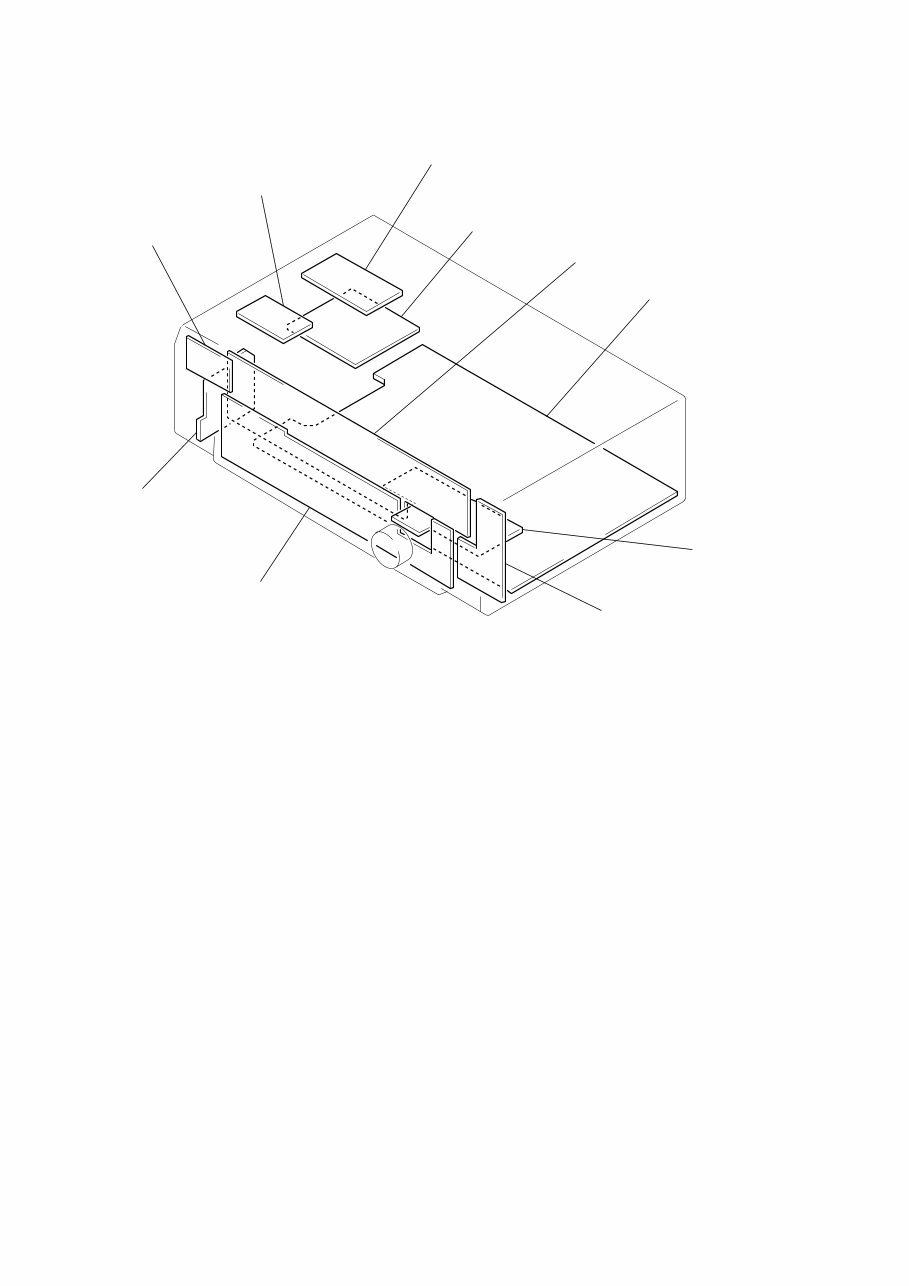
– 8 – • Circuit Boards Location SECTION 5 DIAGRAMS POWER SWITCH board PRIMARY board SECONDARY board STANDBY TRANS board DISPLAY board VOLUME board TONE board KEY board SPK SWITCH board MAIN board
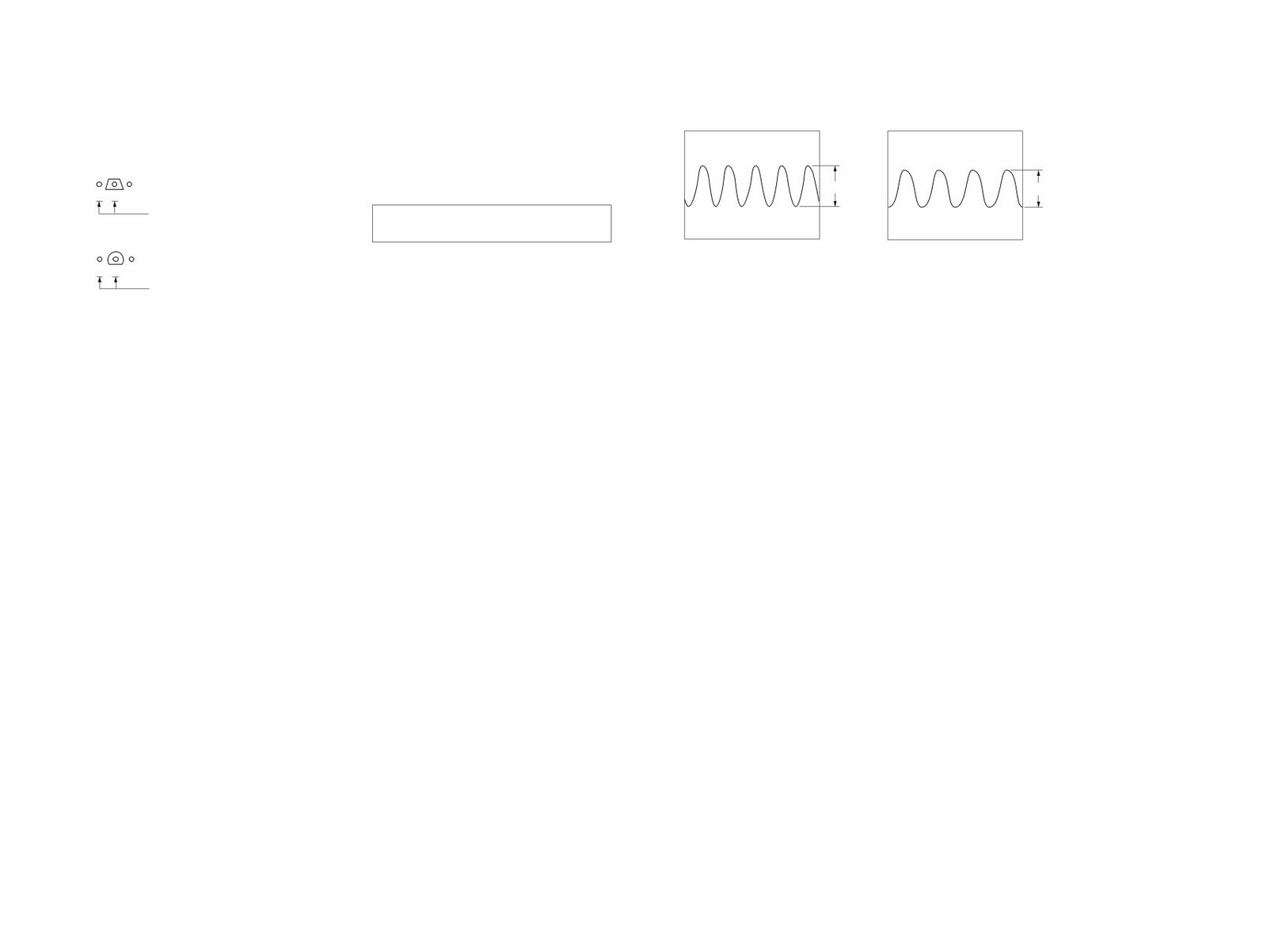
– 9 – – 10 – 5-1. NOTES FOR PRINTED WIRING BOARDS AND SCHEMATIC DIAGRAMS Note on Printed Wiring Board: • X : parts extracted from the component side. • b: Pattern from the side which enables seeing. (The other layers' patterns are not indicated.) • Indication of transistor. B These are omitted. C E Q • Waveforms – MAIN Board – 1 IC1 !¢ (XO) Note on Schematic Diagram: • All capacitors are in μF unless otherwise noted. pF: μμF 50 WV or less are not indicated except for electrolytics and tantalums. • All resistors are in Ω and 1 /4 W or less unless otherwise specified. • ¢ : internal component. • 2 : nonflammable resistor. • C : panel designation. Note: The components identified by mark ! or dotted line with mark ! are critical for safety. Replace only with part number specified. • U : B+ Line. • V : B– Line. • Voltages and waveforms are dc with respect to ground under no-signal (detuned) conditions. no mark : FM • Voltages are taken with a VOM (Input impedance 10 MΩ). Voltage variations may be noted due to normal produc- tion tolerances. • Waveforms are taken with a oscilloscope. Voltage variations may be noted due to normal produc- tion tolerances. • Circled numbers refer to waveforms. • Signal path. F : FM 1.6 Vp-p 4.33 MHz – DISPLAY Board – 1 IC201 #∞ (X2) 5.4 Vp-p 4.19 MHz B These are omitted. C E Q
The Sony STR-DE135 Stereo Receiver Service Manual is a comprehensive technical document designed for audio technicians and enthusiasts. It provides a detailed breakdown of the receiver's inner workings, electronic components, and mechanical systems. The manual includes schematics, circuit diagrams, and step-by-step servicing procedures for diagnostics and repair tasks. It is an indispensable tool for addressing issues related to audio quality, connectivity, and overall functionality.
This manual is dedicated to providing the technical insights needed to ensure optimal performance and longevity of the Sony STR-DE135 Stereo Receiver. Whether you're a professional audio technician or a DIY enthusiast, this manual equips you with the technical knowledge required to service and maintain your equipment accurately.
Printable: Yes
Language: English
Compatibility: Pretty much any electronic device, including PC & Mac computers, Android and Apple smartphones & tablets, etc.




 Lifetime Access




