

Onkyo TX-NR901 Service Manual and Repair Guide
What's Included?
Fast Download Speeds
Online & Offline Access
Access PDF Contents & Bookmarks
Full Search Facility
Print one or all pages of your manual
TX-NR901
SERVICE MANUAL SERVICE MANUAL
AV RECEIVER
Black and Golden models
MODEL TX-NR901
Ref. No. 3786
112003
BMDD,BMDC 120V, AC 60Hz
GMWT,GMWR 120/220~230V, AC 50/60Hz
BMPA,GMPA 230~240V, AC 50Hz
GMGK 220V, AC 50Hz
--/---
@. -' / ABC DEF
PQRS TUV WXYZ
DIRECT TUNING
GHI JKL MNO
CAPS DELETE LANGUAGE LOCATION
ALBUM ARTIST GENRE PLAYLIST
CUSTOM
DISPLAY
DIMMER
TV
INPUT
SLEEP
RANDOM REC STEP/SLOW
MUTING
ENTER
LAST M ANGLE SUBTITLE AUDIO
MEMORY SEARCH A-B REPEAT
ON STANDBY
TV
TV CH
TV VOL
A
U
DIO
A
D
J
E
XIT
G
U
ID
E
+10 0 CLEAR
1 2 3
4 5 6
7 8 9
INPUT
TOP
MENU
M
E
N
U
S
E
T
U
P
R
E
T
U
R
N
ZONE2
INPUT MODE
MACRO
VOL CH
DISC
TEST TONE CH SEL
PURE A
SURR
DIRECT
STEREO
Re-EQ
THX All ST
LEVEL+ LEVEL-
L NIGHT AUDIOSEL
DSP DSP
+
-
+
-
STANDBY/ON
STANDBY
MASTER VOLUME
TUNER PHONO NET AUDIO CD TAPE DVD VIDEO 3 VIDEO 5 VIDEO 4 VIDEO 2 VIDEO 1
VCR 2 VCR 1
ZONE2( ) GRN
REC ( ) RED
AUDIO
SELECTOR DISPL AY PURE AUDIO UPSAMPLING
PUSH TO OPEN
SAFETY-RELATED COMPONENT
WARNING!!
COMPONENTS IDENTIFIED BY MARK ON THE
SCHEMATIC DIAGRAM AND IN THE PARTS LIST ARE
CRITICAL FOR RISK OF FIRE AND ELECTRIC SHOCK.
REPLACE THESE COMPONENTS WITH ONKYO
PARTS WHOSE PART NUMBERS APPEAR AS SHOWN
IN THIS MANUAL.
MAKE LEAKAGE-CURRENT OR RESISTANCE
MEASUREMENTS TO DETERMINE THAT EXPOSED
PARTS ARE ACCEPTABLY INSULATED FROM THE
SUPPLY CIRCUIT BEFORE RETURNING THE
APPLIANCE TO THE CUSTOMER.

TX-NR901/E
SPECIFICATIONS
Amplifier Section
Video Section
Tuner Section
FM
AM
General
Video Inputs
Video Outputs
Audio Inputs
Audio Outputs
Other Sockets
Specifications and features are subject to change without
notice.
Power output:
All channels:
110 W (8 , 20 Hz–20 kHz, FTC)
(American Model)
180 W (6 , 1 kHz, EIAJ) (Asian Model)
150 W (6 , 1 kHz, DIN)
(Australian model)
Dynamic power: 2 x 280 W (3 , front)
2 x 220 W (4 , front)
2 x 140 W (8 , front)
THD (total harmonic
distortion): 0.08% (rated power)
Damping factor: 60
Input sensitivity and
impedance: 200 mV/50k (LINE)
2.5 mV/50k (PHONO MM)
Output level and
impedance: 200 mV/470 (REC OUT)
Phono overload: 120 mV (MM, 1 kHz, 0.5%)
Frequency response: 10 Hz–100 kHz/+1 dB, –3 dB (CD,
Direct)
Tone control: ±10 dB, 50 Hz (BASS)
±10 dB, 20,000 Hz (TREBLE)
S/N ratio (Direct mode):110 dB (LINE, IHF-A, 0.5 V input)
80 dB (PHONO, IHF-A, 5 mV input)
Speaker impedance: 4–16
Input sensitivity, output
level and impedance: 1.0 Vp-p/75 (component and S-V ideo
Y)
0.7 Vp-p/75 (component P B/CB, PR/CR)
0.286 Vp-p/75 (S-Video C)
1.0 Vp-p/75 (composite)
Component video
frequenc y response: 5 Hz–50 MHz
Tuning frequency range:87.5–108.0 MHz
Usable sensitivity: FM STEREO 17.2 dBf, 2.0 μV (75
IHF)
FM MONO 11.2 dBf, 1.0 μV (75 IHF)
S/N ratio: FM STEREO 70 dB (IHF-A)
FM MONO 76 dB (IHF-A)
THD: FM STEREO 0.3%
FM MONO 0.2%
FM stereo separation: 45 dB at 1 kHz, 30 dB at 100 Hz–10 kHz
Tuning frequency range:530–1710 kHz (American model)
522–1611 kHz (Other models)
Usable sensitivity: 30 μV
S/N ratio: 40 dB
THD: 0.7%
Power supply: American model: AC 120 V, 60 Hz
Australian model:AC 230–240 V, 50 Hz
Others models: AC 220–230 V and 120V
switchable 50/60 Hz
Power consumption: American model: 9.0 A
Australian and Worldwide models: 670 W
Standby power
consumption: 2.5 W
Dimensions
(W x H x D): 17-1/8" x 6-7/8" x 18-1/16"
(435 x 175 x 459 mm)
Weight: American and Australian models:
42.5 Ibs. (19.3 kg)
Worldwide models: 42.3 lbs. (19.2 kg)
Component video inputs: 2 (Input 1, Input 2)
S-Video inputs: 6 (DVD, Video 1–5)
V ideo inputs: 6 (DVD, Video 1–5)
Component video
outputs: 1 (Component Monitor Out)
S-Video outputs: 3 (Video 1 Out, V ideo 2 Out, V ideo
Monitor Out)
Video outputs: 4 (Video 1 Out, V ideo 2 Out, V ideo
Monitor Out, Zone 2 Video Out)
Digital inputs: 8 (Optical 1–4, Optical Video 5 (fix ed, on
front panel), Coaxial 1–3)
Analog inputs: 8 (CD, Phono, Tape, DVD, Video 1–4,
Video 5)
Multichannel analog
inputs:
7.1 ch (Front L/R, Center, Surround L/R,
Surround Back L/R, Subw oofer)
Digital outputs: 2 optical
Analog outputs: 4 (Tape Out, Video 1 Out, Video 2 Out,
Zone 2 Out)
Pre outs: 8 (Front L/R, Center , Surround L/R,
Surround Back L/R or Zone 2 L/R,
Subwoofer)
Subw oofer pre out: 1
Speak er outputs: 7
Phones: 1
RS-232: 1 (not American and Australian models)
IR in/out: 1
12V trigger out: 1
Ethernet (Net-T une) 1 (10Base-T, RJ45)
TX-NR901
SERVICE PROCEDURES 1
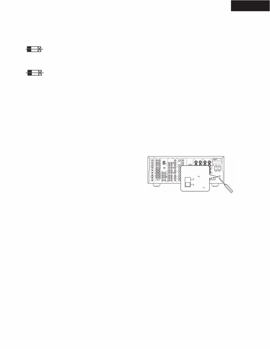
1. Replacing the fuses
This symbol located near the fuses indicates
that the fuse used is fast operating type. For continued
protection against fire hazard, replace with same type fuse.
For fuse rating refer to the marking adjacent to the symbol.
Ce symbole indique que le fusible utlise est a
rapide. Pour une protection permanente, n'untiliser que
fusibles de meme type. Ce darnier est la qu le present
symbol est appse.
2. To initialize the unit
This device employs a microprocessor to perform various
functions and operations. If interference generated by an
external power supply, radio wave, or other electrical source
results in accident which causes the specified operations
and functions to operate abnormally.
To perform a result, please follow the procedure below.
1.Press the STANDBY ON button to turn on the unit.
2.Press and hold down the VIDEO 1 button, then press the
STANDBY/ON button.
3.After "CLEAR" is displayed, the preset memory and each
mode stored in the memory, such as surround, are
initialized and will return to the factory setting.
4.Unplug the power supply cord.
3. Safety-check out
(Only U.S.A. model)
After correcting the original service problem, perform the
following safety check before releasing the set to the
customer. Connect the insulating-resistance tester between
the plug of power supply cord and screw on the back panel.
Specifications: 3.3Mohm+/-10% at 500V.
4. Memory Preservation
This unit does not require memory preservation batteries. A
built-in memory power back-up system preserves the contents
of the memory during power failures and even when the unit is
unplugged. The unit must be plugged in order to charge the
back-up system.
The memory preservation period after the unit has been
unplugged varies depending on climate and placement of the
unit. On the average, memory contents are protected over a
period of a few weeks after the last time the unit has been
unplugged. This period is shorter when the unit is e xposed to a
highly humid climate.
5.Setting the voltage selector
(Worldwide models only)
Worldwide models are equipped with a voltage selector so
that you
supplies. Be
can set your TX-NR901 to conform with local power
sure to set this switch to match the voltage of
your area before plugging in the unit.
Determine the proper voltage for your area: 220-230 V or
the preset voltage is not correct for your area,
into the groove in the switch and slide
(220-230 V), whichever is appropriate.
Note: <D>: 120V model only
<A>: Australian model only
<T>: Worldwide model only
<R>: Chinese model only
the power supply in
120 V. If
insert a screwdriver
the switch all the way to the top (120 V) or bottom
REF. NO. PART NO. DESCRIPTION
F901 252196 12A-UL/T-314,Fuse <D/T/R>
F902 252078 5A-SE-EAK,
252244 or 5A-SE-TL250V or
252278 5A-SE-TL250V, Fuse <T/A/R/K>
F903 252164 or 5A-UL/T-237 or
252258 5A-T/UL-ST2,Fuse <D>
252075, 2.5A-SE-EAK,
252241 or 2.5A-SE-TL250V or
252275 2.5A-SE-TL250V,Fuse <T/A/R/K>
F9501,F9502 252160 or 2.5A-UL/T-237 or
252254 2.5A-T/UL-ST2,Fuse <D>
252075, 2.5A-SE-EAK,
252241 or 2.5A-SE-TL250V or
252275 2.5A-SE-TL250V,Fuse <T/A/R/K>
F9503,F9504 252158 or 1.6A-UL/T-237 or
252252 1.6A-T/UL-ST2,Fuse <D>
252073, 1.6A-SE-EAK,
252239 or 1.6A-SE-TL250V or
252273 1.6A-SE-TL250V,Fuse <T/A/R/K>
<K>: Korean model only
FM
75
OUT
OUT
OUT
L
PHONO
DIGITAL
IN
PRE OUT
DIGITAL
OUT
OPT
OPT
2
1
2
3
4
1
2
FRONT
SUB
SURR
R L
AUDIO
R L
CD
TAPE
R L
AUDIO VIDEO S VIDEO
MONITOR
OUT
R L
IN
IN
IN
IN
IN
IN
IN
ZONE 2
DVD
VIDEO 1
VIDEO 2
VIDEO 3
VIDEO 4
AUDIO AUDIO VIDEO S VIDEO
3
GND
SURR BACK/ ZONE 2
R L
IN
ACINLET
COAX
R
ZONE 2
REMOTE
CONTROL
RS232
IR 12V TRIGGER OUT
IN
CENTER
ETHERNET
(Net -Tune)
R L
MULTI CH
INPUT
FRONT
SUB
SURR
SURR
BACK
CENTER
R L
AM
ANTENNA
COMPONENT
VIDEO
Y
P
P
OUTPUT
INPUT 1
Y
P
P
INPUT 2
Y
P
P
VOLTAGE
SELECTOR
220- 230V
1 20V
TX-NR901
MODEL NO. /
SURR
BACK/
ZONE 2
SPEAKERS
FRONT SPEAKERS
L R L R
SURR SPEAKERS
CENTER
SPEAKER
R L
VOLTAGE
SELECTOR
220- 230V
1 20V
TX-NR901
SERVICE PROCEDURES 2
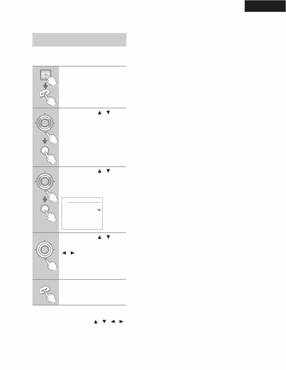
This section explains ho w to specify the AM frequenc y
step. (This setting is not available on American and Aus-
tralian models.)
Note:
* This procedure can also be performed by using the
TX-NR901's [SETUP] button, [ ]/[ ]/[ ]/[ ]
buttons, and [ENTER] button.
Specifying the AM Frequency Step
(Worldwide model only)
1
Press the scroll wheel, and then
press the [SETUP] button.
The main menu appears onscreen.
2
Use the Up/Down [ ]/[ ] but-
tons to select "0. Hardware
Setup," and then press the
[ENTER] button.
The Hardware Setup menu appears.
3
Use the Up/Down [ ]/[ ] but-
tons to select "5. AM Frequency
Step," and then press the
[ENTER] button.
The AM Frequenc y Step menu appears.
4
Use the Up/Down [ ]/[ ] but-
tons to select "a. Frequency
Step," and then use the Left/Right
[ ]/[ ] buttons to select:
10 kHz: Select if 10 kHz steps are
used in your area.
9 kHz: Select if 9 kHz steps are used
in your area.
5
Press the [SETUP] button.
The setup menu closes.
ENTER
ENTER
ENTER
ENTER
0-5.AM Frequency Step
a.Frequency Step
:9 kHz
Quit:[SETUP]
ENTER
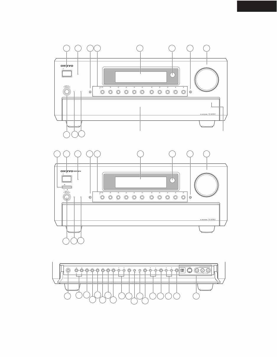
TX-NR901
FRONT PANEL
4 6 7
12
11
13
16
19
21
5 8 9
10
15 14
17
18 20
3
26
23
22
25
24
2
27 29 28 30
STANDBY/ON
STANDBY
MASTER VOLUME
TUNER PHONO NET AUDIO CD TAPE DVD VIDEO 3 VIDEO 5 VIDEO 4 VIDEO 2 VIDEO 1
VCR 2 VCR 1
ZONE2( ) GRN
REC ( ) RED
AUDIO
SELECTOR DISPL AY PURE AUDIO UPSAMPLING
OFF ON
POWER
PUSH TO OPEN
PHONES
ZONE 2 LEVEL
STEREO SURROUND THX DSP REC OUT ZONE 2 OFF DIMMER MEMORY FM MODE SETUP ENTER RETURN
S VIDEO VIDEO DIGIT AL
VIDEO 5 INPUT
STANDBY/ON
STANDBY
MASTER VOLUME
TUNER PHONO NET AUDIO CD TAPE DVD VIDEO 3 VIDEO 5 VIDEO 4 VIDEO 2 VIDEO 1
VCR 2 VCR 1
ZONE2( ) GRN
REC ( ) RED
AUDIO
SELECTOR DISPL AY PURE AUDIO UPSAMPLING
PUSH TO OPEN
PRESET TUNING CLEAR
AUDIO L R
American and Australian Models
Other Models
Front door Push here to open the flap
4 6 7
12
11
5 8 9
10
3
1
2

TX-NR901
FRONT PANEL
POWER switch
American and Australian models don’ t have this
switch.
This is the main power switch. When set to OFF, the
TX-NR901 is completely shutdown. When set to
ON, the TX-NR901 is in Standby mode and the
STANDBY indicator lights up.
Don’t turn on the power until you’ve completed,
and double checked all connections.
STANDBY/ON button
This button is used to set the TX-NR901 to On or
Standby . For models with a POWER switch, this
button has no effect unless the POWER switch is set
to ON.
STANDBY indicator
This indicator lights up when the TX-NR901 is in
Standby mode, and it ashes while a signal is being
received from the remote controller .
AUDIO SELECTOR button
This button is used to select the audio input signal
format: analog, digital, or multichannel.
Input selector buttons & indicators
These buttons are used to select the following input
sources: DVD, VIDEO 1–5,TAPE, TUNER,
PHONO, CD, and NET AUDIO. The indicators
show the currently selected input source.
The indicators also show which input source is
selected for Zone 2, in which case they light up
green, or which input source is selected for record-
ing (REC OUT), in which case they light up red.
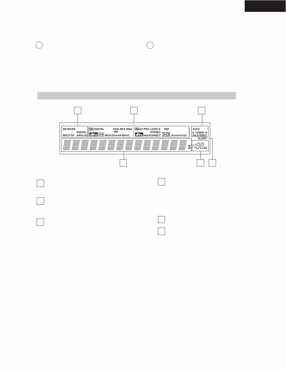
Display
See “Display” on next page.
Remote-control sensor
This sensor receives control signals from the remote
controller.
DISPLAY button
This button is used to display various information
about the currently selected input source.
MASTER VOLUME control
This control is used to set the volume of the
TX-NR901 from 0 to 100.
DIRECT/PURE AUDIO button
This button is used to select the Direct or Pure
Audio listening modes.
PURE AUDIO indicator
This indicator lights up when the Pure Audio listen-
ing mode is selected.
UPSAMPLING indicator
This indicator lights up when the Upsampling func-
tion is on.
PHONES jack
This 1/4-inch phone jack is for connecting a stan-
dard pair of stereo headphones for private listening.
ZONE 2 LEVEL [ ] [ ] buttons
These buttons are used to set the volume for Zone 2.
REC OUT button
This button is used to select the input source that
you want to record via the REC OUTs (i.e., TAPE
OUT, VIDEO 1 OUT, VIDEO 2 OUT).
ZONE 2 button
This button is used to select the input source for
Zone 2.
OFF button
This button is used to turn of f the REC OUTs (i.e.,
TAPE OUT, VIDEO 1 OUT, VIDEO 2 OUT) or
Zone 2.
STEREO button
This button is used to select the Stereo listening
mode.
SURROUND button
This button is used to select the Dolby and DTS lis-
tening modes.
THX button
This button is used to select the THX listening
modes.
DSP [ ] [ ] buttons
These buttons are used to select the DSP (digital
signal processor) listening modes.
DIMMER button
This button is used to adjust the display brightness.
MEMORY button
This button is used when storing and deleting radio
presets.
FM MODE button
This button is used to select the FM radio Auto and
Mono modes.
SETUP button
This button is used to access the onscreen setup
menus (OSD) that appear on the TV .
TUNING [ ] [ ] buttons
These buttons are used to tune into radio stations
and to select items on the onscreen setup menus
(OSD).
ENTER button
This button is used when navigating the onscreen
setup menus (OSD), entering names, and confirm-
ing settings.
PRESET [ ] [ ] buttons
These buttons are used to select radio presets and to
select items on the onscreen setup menus (OSD).
4
6
7
12
11
13
16
19
21
5
8
9
10
15
14
17
18
20
3
26
23
22
25
24
1
2
27
28
TX-NR901
FRONT PANEL
RETURN button
This button is used to return to the previously dis-
played onscreen setup menu (OSD).
VIDEO 5 INPUTs
These optical digital audio, S-V ideo, composite
video, and analog audio inputs can be used to con-
nect a camcorder, games console, and so on.
Audio input format indicators
These indicators show the audio input format for the
currently selected input source.
Listening mode & digital audio format
indicators
These indicators show the currently selected listen-
ing mode and digital audio format.
Tuning indicators
AUTO indicator:
This indicator lights up when the tuner is tuned to
an FM station and Stereo mode is selected. It goes
off when Mono mode is selected.
TUNED indicator:
This indicator lights up when the tuner is tuned into
an AM or FM station.
FM STEREO indicator:
This indicator lights up when the tuner is tuned to a
stereo FM station. It goes of f when Mono mode is
selected.
Multipurpose display area
Normally, the name of the currently selected input
source is displayed here. When you select the AM
or FM input source, the radio frequency and preset
number are displayed. If you press the [DISPLA Y]
button, the currently selected listening mode and
digital audio format are displayed.
Volume level
The volume level is displayed here.
SLEEP indicator
This indicator lights up when the Sleep function has
been set.
Displa y
29
30
2 3
4 5
1
6
2
3
4
5
1
6
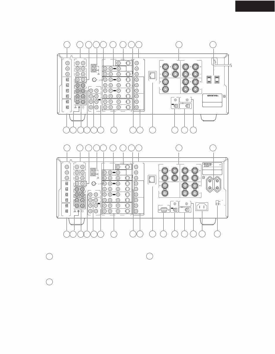
TX-NR901
REAR PANEL
DIGITAL IN COAX 1–3, OPT 1–4
These coaxial and optical digital audio inputs can be
used to connect CD, DVD, or LD (laser disc) play-
ers and other components with digital audio outputs.
DIGITAL OUT OPT 1 & 2
These optical digital audio outputs can be used to
connect a CD recorder or other digital recorder with
digital inputs.
PRE OUT—FRONT L/R, SUB, CENTER,
SURR L/R
If you use the TX-NR901 as a preamp, these analog
audio outputs can be connected to the inputs on a
separate power amp. The SUB output is used to
connect a powered subwoofer .
FM
75
OUT
OUT
OUT
OUT
L
OUT
PHONO
DIGITAL
IN
PRE OUT
DIGITAL
OUT
OPT
OPT
2
1
2
3
4
1
2
FRONT
SUB
SURR
R L
AUDIO
R L
CD
TAPE
R L
AUDIO VIDEO S VIDEO
MONITOR
OUT
R L
IN
IN
IN
IN
IN
IN
IN
ZONE 2
DVD
VIDEO 1
VIDEO 2
VIDEO 3
VIDEO 4
AUDIO AUDIO VIDEO S VIDEO
1
3
GND
SURR
BACK/
ZONE 2
R L
IN
AC INLET
COAX
R
ZONE 2
REMOTE
CONTROL
RS232
I R 12V TRIGGER OUT
IN
CENTER
ETHERNET
(Net -Tune)
R L
MULTI CH
INPUT
FRONT
SUB
SURR
SURR
BACK
CENTER
R L
AM
ANTENNA
COMPONENT
VIDEO
Y
PB
PR
OUTPUT
INPUT 1
Y
PB
PR
INPUT 2
Y
PB
PR
VOLTAGE
SELECTOR
220- 230V
1 20V
TX-NR901
MODEL NO. /
SURR
BACK/
ZONE 2
SPEAKERS
FRONT SPEAKERS
L R L R
SURR SPEAKERS
CENTER
SPEAKER
R L
FM
75
OUT
OUT
OUT
OUT
L
OUT
PHONO
DIGITAL
IN
PRE OUT
DIGITAL
OUT
OPT
OPT
2
1
2
3
4
1
2
FRONT
SUB
SURR
R L
AUDIO
R L
CD
TAPE
R L
AUDIO VIDEO S VIDEO
MONITOR
OUT
R L
IN
IN
IN
IN
IN
IN
IN
ZONE 2
DVD
VIDEO 1
VIDEO 2
VIDEO 3
VIDEO 4
AUDIO AUDIO VIDEO S VIDEO
1
3
GND
SURR
BACK/
ZONE 2
R L
IN
COAX
R
ZONE 2
REMOTE
CONTROL
I R 12V TRIGGER OUT
IN
CENTER
ETHERNET
(Net -Tune)
R L
MULTI CH
INPUT
FRONT
SUB
SURR
SURR
BACK
CENTER
R L
AM
ANTENNA
COMPONENT
VIDEO
Y
PB
PR
OUTPUT
INPUT 1
Y
PB
PR
INPUT 2
Y
PB
PR
AC OUTLETS
AC 120V 60Hz
SWITCHED
TOTAL 120W 1A MAX.
AV RECEIVER
MODEL NO. TX-NR 901
SURR
BACK/
ZONE 2
SPEAKERS
FRONT SPEAKERS
L R L R
SURR SPEAKERS
CENTER
SPEAKER
R L
American and Australian Models
Other Models
21
1 3 4 6 7 12 11 13 16 19 26
2 27 5 8 9 10 15 14 17 18 23 22
21 2 27 5 8 9 10 15 14 17 18 23 22 25 24 20
1 3 4 6 7 12 11 13 16 19 26
1 3
2

TX-NR901
REAR PANEL
4
6
7
12
11
13
16
19
26
21
5
8
9
10
15
14
17
18
23
22
25
24
20
PRE OUT—SURR BACK/ZONE 2
These analog audio outputs can be used to feed the
L/R surround back inputs on a separate power amp
when the TX-NR901 is used as a preamp, or to feed
a po wer amp in Zone 2.
MULTI CH INPUT—FRONT L/R, SUB,
CENTER, SURR L/R, SURR BACK L/R
These analog audio inputs can be used to connect AV
components with multiple analog audio outputs,
including DVD players with indi vidual 5.1/7.1 sur -
round analog audio outputs.
AM ANTENNA
These push terminals are for connecting an AM
antenna.
FM ANTENNA
This connector is for connecting an FM antenna.
PHONO IN
These analog inputs can be used to connect a turnta-
ble with a moving-magnet cartridge.
CD IN
These analog inputs can be used to connect a CD
player with analog outputs.
TAPE IN/OUT
These analog inputs and outputs can be used to con-
nect a cassette recorder , Mini Disc recorder , or other
recorder with analog inputs and outputs.
MONITOR OUT
This S-V ideo or composite video output can be con-
nected to the video input on your TV or projector.
ZONE 2 OUT
These composite video and analog audio outputs
can be used to feed a TV and an inte grated amp in
Zone 2.
DVD IN
These S-V ideo, composite video, and analog audio
inputs can be used to connect a D VD player.
VIDEO 1 & 2 IN/OUT
These S-V ideo, composite video, and analog audio
inputs and outputs can be used to connect one or
two video recorders (e.g., VCRs).
VIDEO 3 & 4 IN
These S-V ideo, composite video, and analog audio
inputs can be used to connect one or two video
sources (e.g., cable TV, satellite TV , or a set-top
box).
COMPONENT VIDEO OUTPUT
This component video output can be used to con-
nect a TV or projector with a component video
input.
COMPONENT VIDEO INPUT 1 & 2
These component video inputs can be used to con-
nect one or two AV components with component
video outputs, such as a DVD player.
ETHERNET (Net-Tune)
This port is for connecting the TX-NR901 to your
Ethernet network (i.e., router or switch) for use with
Net-Tune (i.e., Internet radio and MP3, WAV, and
WMA playback).
SPEAKERS
These terminal posts are for connecting your speak-
ers.The SURR BA CK/ZONE 2 terminals can be
used with surround back speakers in the main room
or speak ers in another room (Zone 2).
RS232
This port is for connecting the TX-NR901 to home
automation and external controllers.
American and Australian models don't have this
port.
IR IN/OUT
If you want to use the remote controller to control
the TX-NR901 from Zone 2, or if the TX-NR901 is
installed in a cabinet and the line of sight between
the TX-NR901 and the remote controller is
obstructed, a commercially available IR receiver
can be connected to the IR IN. A commercially
available IR emitter can be connected to the IR
OUT to pass the IR signals along to another AV
component.
ZONE 2 12V TRIGGER OUT
This output can be connected to the 12-v olt trigger
input on a power amp in Zone 2. The power amp
can then be turned on or of f automatically from the
TX-NR901.
REMOTE CONTROL
This (Remote Interactive) socket can be con-
nected to the socket on another Onkyo AV com-
ponent. The TX-NR901’ s remote controller can
then be used to control that component. To use ,
you must mak e an analog RCA/phono audio con-
nection between the TX-NR901 and the other AV
component, even if they are connected digitally .
AC INLET
The supplied power cord should be connected here.
American and Australian models do not have an A C
INLET. The y have an integral power cord instead.
VOLTAGE SELECTOR
This voltage selector provides compatibility with
power systems around the world.
American and Australian models don’ t have this
selector .
AC OUTLETS
These switched AC outlets can be used to supply
power to other A V components. The connector type
depends on the country in which you purchased
your TX-NR901.
Grounding screw
This scre w is for connecting a turntable’ s ground
wire.
27
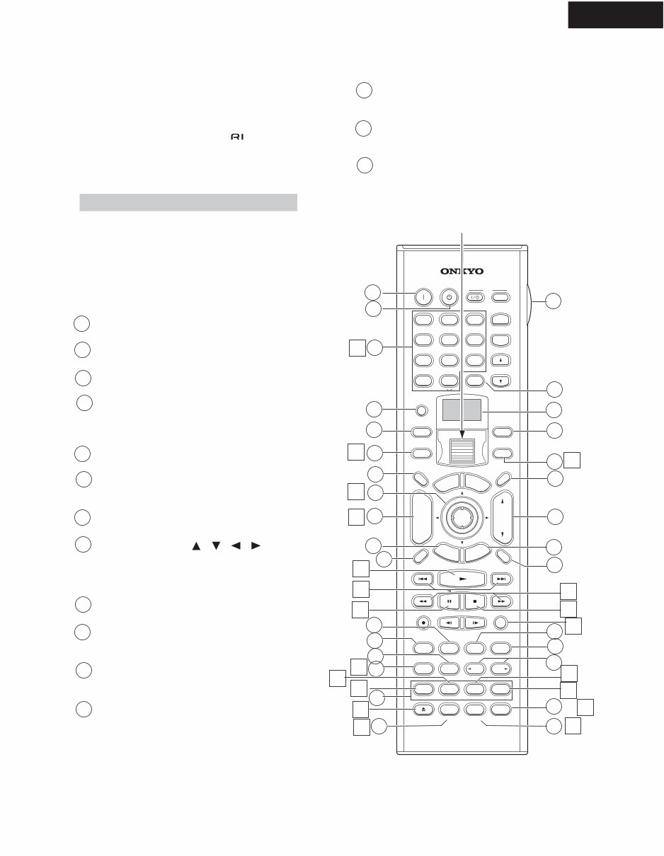
TX-NR901
REMOTE CONTROLLER
4
6
7
12
11
13
16
19
21 5
8
9
10
15
14
17
18
20
The TX-NR901’ s remote controller is a multipurpose
device that can be used to control not just the TX-NR901
but your other A V components as well. This section
explains how it’s various operating modes can be used to
control the TX-NR901 and various -compatible
Onk yo components.
Amp mode is used to control the TX-NR901. To select
Amp mode, press the scr oll wheel. “ AMP” appears
on the display .
Note:
While neither the [INPUT] button nor [MODE] button is
illuminated, rolling the scroll wheel changes the input
source and remote controller mode simultaneously .
Box ed numbers are for Net-Tune mode.
ON button
This button is used to turn on the TX-NR901.
STANDBY button
This button is used to set the TX-NR901 to Standby .
Number/letter buttons
These buttons are used to enter numbers and letters.
CUSTOM button
This button is used to access various settings that
you can use to customize the operation of the
remote controller .
MACRO button
This button is used with the Macro function.
MODE button
This button is used with the scroll wheel to select
the remote controller modes.
DIMMER button
This button is used to adjust the display brightness.
Up/Down/Left/Right [ ]/[ ]/[ ]/[ ] &
ENTER buttons
These buttons are used to select items on the
onscreen setup menus (OSD).The ENTER button is
also used to enter names and to confirm settings.
CH/DISC button
This button is used to select radio presets.
RETURN/EXIT button
This button is used to return to the previously dis-
played onscreen setup menu (OSD).
DISPLAY button
This b utton is used to display various information
about the currently selected input source.
THX button
This button is used to select the THX listening
modes.
SURR button
This button is used to select the Dolby and DTS lis-
tening modes.
DIRECT button
This button is used to select the Direct listening
mode.
PURE A button
This button is used to select the Pure Audio listen-
ing mode.
Amp Mode
--/---
@. - ' / ABC DEF
PQRS TUV WXYZ
DIRECT TUNING
GHI JKL MNO
CAPS DELETE LANGUAGE LOCATION
ALBUM ARTIST GENRE PLAYLIST
CUSTOM
DISPLAY
DIMMER
TV
INPUT
SLEEP
RANDOM REC STEP/ SLOW
MUTING
ENTER
LAST M ANGLE SUBTITLE AUDIO
MEMORY SEARCH A-B REPEAT
ON STANDBY
TV
TV CH
TV VOL
A
U
D
I
O
A
D
J
E
X
I
T
G
U
I
D
E
+10 0 CLEAR
1 2 3
4 5 6
7 8 9
INPUT
T
O
P
M
E
N
U
M
E
N
U
S
E
T
U
P
R
E
T
U
R
N
ZONE2
INPUT MODE
MACRO
VOL
CH
DISC
TEST TONE CH SEL
PURE A
SURR
DIRECT
STEREO
Re-EQ
THX All ST
LEVEL+ LEVEL-
L NIGHT AUDIOSEL
DSP DSP
+
-
+
-
2
3
4
5
1
9
8
10
11
12
6
7
Scr oll wheel
3
1
2
4
6
7
12
11
13
26
5
8
9
10
15
14
23
22
25
24
3
1
2
27
29
28
30
31
13
14
15
16
17
18
19
20
You're Reading a Preview
What's Included?
Fast Download Speeds
Online & Offline Access
Access PDF Contents & Bookmarks
Full Search Facility
Print one or all pages of your manual
$31.99
Viewed 58 Times Today


Secure transaction
What's Included?
Fast Download Speeds
Online & Offline Access
Access PDF Contents & Bookmarks
Full Search Facility
Print one or all pages of your manual
$31.99
This service and repair manual is an essential resource for both professional Onkyo technicians and DIY enthusiasts. It provides comprehensive guidance with fully illustrated schematic diagrams, block diagrams, printed circuit boards, terminal descriptions, exploded views, and a complete parts list catalog.
Upon payment, you will have instant access to the manual, eliminating shipping fees and postal delivery wait times. This manual is available in English and consists of 159 pages.


