

Marantz SR6006 Service Manual and Repair Guide
What's Included?
Fast Download Speeds
Online & Offline Access
Access PDF Contents & Bookmarks
Full Search Facility
Print one or all pages of your manual
Service
Manual
• Some illustrations using in this service manual are slightly different from the actual set.
• Please use this service manual with referring to the operating instructions without fail.
• For purposes of improvement, specifications and design are subject to change without notice.
AV Surround Receiver
SR6006 /U1B/N1B/N1SG/K1B
SR6006
S0325-0V03DM/DG1108 Copyright 2011 D&M Holdings Inc. All rights reserved.
WARNING: Violators will be prosecuted to the maximum extent possible.
Ver. 3
Please refer to the
MODIFICATION NOTICE.

2
CONTENTS
SAFETY PRECAUTIONS ..........................................................3
NOTE FOR SCHEMATIC DIAGRAM.........................................4
TECHNICAL SPECIFICATIONS ................................................5
DIMENSION ...............................................................................6
CAUTIONS IN SERVICING .......................................................7
Initializing AV Surround Receiver ..............................................7
Service Jig ................................................................................7
DISASSEMBLY ..........................................................................8
1. FRONT PANEL ASSY .........................................................10
2. HEAT SINK ASSY ............................................................... 11
3. HDMI UNIT ASSY................................................................13
4. TRANS MAIN ......................................................................16
SPECIAL MODE ......................................................................17
Special mode setting button ....................................................17
1. µcom/DSP Version display mode ........................................18
2. Errors checking mode (Displaying the protection history) ...22
3. DUAL BACKUP MEMORY ..................................................24
PROTECTION DIAGRAM .......................................................25
4. DIAGNOSTIC MODE (Video/Audio (signal)
path confirmation mode) .........................................................26
BLOCK DIAGRAM ..................................................................30
JIG FOR SERVICING ..............................................................61
WHEN THE MICROPROCESSOR IS REPLACED
WITH A NEW ONE...................................................................65
PROCEDURE FOR UPGRADING THE VERSION
OF THE FIRMWARE................................................................65
ADJUSTMENT .........................................................................72
SURROUND MODES AND PARAMETERS ............................73
TROUBLE SHOOTING ............................................................77
1. POWER...............................................................................77
2. Analog video........................................................................78
3. HDMI/DVI ............................................................................84
4. AUDIO .................................................................................93
5. Network/USB .......................................................................96
6. SMPS ..................................................................................99
CLOCK FLOW & WAVE FORM IN DIGITAL BLOCK ...........102
LAEVEL DIAGRAM ...............................................................103
PRINTED WIRING BOARDS.................................................109
7CH AMP (COMPONENT SIDE) ..........................................109
7CH AMP (FOIL SIDE) ..........................................................109
SMPS (COMPONENT SIDE) ................................................ 110
SMPS (FOIL SIDE) ............................................................... 110
SPK_PREOUT (COMPONENT SIDE) .................................. 111
SPK_PREOUT (FOIL SIDE) ................................................. 112
INPUT (COMPONENT SIDE) ............................................... 113
INPUT (FOIL SIDE) ............................................................... 114
FUSE (COMPONENT SIDE)................................................. 115
F_WIDE (COMPONENT SIDE)............................................. 115
RS232C_CNT (COMPONENT SIDE) ................................... 115
FUSE (FOIL SIDE) ................................................................ 115
F_WIDE (FOIL SIDE) ............................................................ 115
RS232C_CNT (FOIL SIDE)................................................... 115
POSISTOR (COMPONENT SIDE)........................................ 115
POSISTOR (FOIL SIDE) ....................................................... 115
FRONT (COMPONENT SIDE) .............................................. 116
V.AUX (FOIL SIDE) ............................................................... 116
FRONT (FOIL SIDE) ............................................................. 116
V.AUX (COMPONENT SIDE)................................................ 116
HDMI FFC (COMPONENT SIDE) ......................................... 117
GUIDE TOP (COMPONENT SIDE)....................................... 117
GUIDE L (COMPONENT SIDE) ............................................ 117
HDMI FFC (FOIL SIDE) ........................................................ 117
GUIDE TOP (FOIL SIDE) ...................................................... 117
GUIDE L (FOIL SIDE) ........................................................... 117
USB (COMPONENT SIDE) ................................................... 117
HP (COMPONENT SIDE) ..................................................... 117
GUIDE R (COMPONENT SIDE) ........................................... 117
USB (FOIL SIDE) .................................................................. 117
HP (FOIL SIDE)..................................................................... 117
GUIDE R (FOIL SIDE)........................................................... 117
RS232C (COMPONENT SIDE)............................................. 118
RS232C (FOIL SIDE) ............................................................ 118
SIDE_CNT (COMPONENT SIDE) ........................................ 119
SIDE_CNT (FOIL SIDE) ........................................................ 119
VIDEO (COMPONENT SIDE) ...............................................120
VIDEO (FOIL SIDE) ..............................................................121
FRONT CNT (COMPONENT SIDE) .....................................122
FRONT CNT (FOIL SIDE) .....................................................123
HDMI (COMPONENT SIDE) .................................................124
HDMI (FOIL SIDE) ................................................................125
SCHEMATIC DIAGRAMS......................................................126
USB UNIT..............................................................................126
FRONT UNIT.........................................................................126
AMP UNIT (1/2) .....................................................................127
AMP UNIT (2/2) .....................................................................128
SPK/PREOUT/REG UNIT (1/4).............................................129
SPK/PREOUT/REG UNIT (2/4).............................................130
SPK/PREOUT/REG UNIT (3/4).............................................131
SPK/PREOUT/REG UNIT (4/4).............................................132
CNT/RS232C UNIT (1/3).......................................................133
CNT/RS232C UNIT (2/3).......................................................134
CNT/RS232C UNIT (3/3).......................................................135
INPUT UNIT ..........................................................................136
VIDEO UNIT..........................................................................137
SMPS UNIT...........................................................................138
DIGITAL UNIT (1/16) .............................................................139
DIGITAL UNIT (2/16) .............................................................140
DIGITAL UNIT (3/16) .............................................................141
DIGITAL UNIT (4/16) .............................................................142
DIGITAL UNIT (5/16) .............................................................143
DIGITAL UNIT (6/16) .............................................................144
DIGITAL UNIT (7/16) .............................................................145
DIGITAL UNIT (8/16) .............................................................146
DIGITAL UNIT (9/16) .............................................................147
DIGITAL UNIT (10/16) ...........................................................148
DIGITAL UNIT (11/16) ...........................................................149
DIGITAL UNIT (12/16) ...........................................................150
DIGITAL UNIT (13/16) ...........................................................151
DIGITAL UNIT (14/16) ...........................................................152
DIGITAL UNIT (15/16) ...........................................................153
DIGITAL UNIT (16/16) ...........................................................154
WIRING DIAGRAM ................................................................155
EXPLODED VIEW .................................................................156
PARTS LIST OF EXPLODED VIEW......................................158
PACKING VIEW .....................................................................161
PARTS LIST OF PACKING & ACCESSORIES.....................161
SEMICONDUCTORS .............................................................163
1. IC's ....................................................................................163
2. FL DISPLAY.......................................................................193
PARTS LIST OF P.C.B. UNIT ................................................194
PCB FRONT ASSY ...............................................................194
PCB 7CH_AMP ASSY...........................................................196
PCB CNT ASSY ....................................................................201
PCB MAIN ASSY...................................................................203
PCB INPUT ASSY.................................................................208
PCB VIDEO ASSY ................................................................210
PCB SMPS ASSY .................................................................212
PCB HDMI ASSY ..................................................................214

3
SAFETY PRECAUTIONS
The following items should be checked for continued protection of the customer and the service technician.
LEAKAGE CURRENT CHECK
Before returning the set to the customer, be sure to carry out either (1) a leakage current check or (2) a line to chassis
resistance check. If the leakage current exceeds 0.5 milliamps, or if the resistance from chassis to either side of the
power cord is less than 460 kohms, the set is defective.
Be sure to test for leakage current with the AC plug in both polarities, in addition, when the set's power is in each state (on,
off and standby mode), if applicable.
CAUTION Please heed the following cautions and instructions during servicing and
inspection.
◎ Heed the cautions!
Cautions which are delicate in particular for servicing
are labeled on the cabinets, the parts and the chassis,
etc. Be sure to heed these cautions and the cautions
described in the handling instructions.
◎ Cautions concerning electric shock!
(1) An AC voltage is impressed on this set, so if
you touch internal metal parts when the set is
energized, you may get an electric shock. Avoid
getting an electric shock, by using an isolating
transformer and wearing gloves when servicing
while the set is energized, or by unplugging the
power cord when replacing parts, for example.
(2) There are high voltage parts inside. Handle with
extra care when the set is energized.
◎ Caution concerning disassembly and
assembly!
Through great care is taken when parts were
manufactured from sheet metal, there may be burrs
on the edges of parts. The burrs could cause injury if
fingers are moved across them in some rare cases.
Wear gloves to protect your hands.
◎ Use only designated parts!
The set's parts have specific safety properties (fire
resistance, voltage resistance, etc.). Be sure to use
parts which have the same properties for replacement.
The burrs have the same properties. In particular, for
the important safety parts that are indicated by the z
mark on schematic diagrams and parts lists, be sure to
use the designated parts.
◎ Be sure to mount parts and arrange the wires
as they were originally placed!
For safety seasons, some parts use tapes, tubes or
other insulating materials, and some parts are mounted
away from the surface of printed circuit boards.
Care is also taken with the positions of the wires by
arranging them and using clamps to keep them away
from heating and high voltage parts, so be sure to set
everything back as it was originally placed.
◎ Make a safety check after servicing!
Check that all screws, parts and wires removed or
disconnected when servicing have been put back in
their original positions, check that no serviced parts
have deteriorate the area around. Then make an
insulation check on the external metal connectors and
between the blades of the power plug, and otherwise
check that safety is ensured.
(Insulation check procedure)
Unplug the power cord from the power outlet,
disconnect the antenna, plugs, etc., and on the power.
Using a 500V insulation resistance tester, check that
the insulation resistance value between the inplug and
the externally exposed metal parts (antenna terminal,
headphones terminal, input terminal, etc.) is 1MΩ or
greater. If it is less, the set must be inspected and
repaired.
Many of the electric and the structural parts used in
the set have special safety properties. In most cases
these properties are difficult to distinguish by sight, and
the use of replacement parts with higher ratings (rated
power and withstand voltage) does not necessarily
guarantee that safety performance will be preserved.
Parts with safety properties are indicated as shown
below on the wiring diagrams and the parts list in this
service manual. Be sure to replace them with the parts
which have the designated part number.
(1) Schematic diagrams.......Indicated by the z mark.
(2) Parts lists.......Indicated by the z mark.
The use of parts other than the
designated parts could cause electric
shocks, fires or other dangerous
situations.
CAUTION Concerning important safety
parts

4
NOTE FOR SCHEMATIC DIAGRAM
WARNING:
Parts indicated by the z mark have critical characteristics. Use ONLY replacement parts recommended by the manufacturer.
CAUTION:
Before returning the set to the customer, be sure to carry out either (1) a leakage current check or (2) a line to chassis resistance check. If
the leakage current exceeds 0.5 milliamps, or if the resistance from chassis to either side of the power cord is less than 460 kohms, the set
is defective.
WARNING:
DO NOT return the set to the customer unless the problem is identified and remedied.
NOTICE:
ALL RESISTANCE VALUES IN OHM. k=1,000 OHM / M=1,000,000 OHM
ALL CAPACITANCE VALUES ARE EXPRESSED IN MICRO FARAD, UNLESS OTHERWISE INDICATED. P INDICATES MICRO-MICRO
FARAD. EACH VOLTAGE AND CURRENT ARE MEASURED AT NO SIGNAL INPUT CONDITION. CIRCUIT AND PARTS ARE SUBJECT
TO CHANGE WITHOUT PRIOR NOTICE.
Parts indicated by "nsp" on this table cannot be supplied.
When ordering a part, make a clear distinction between "1" and "I" (i) to avoid mis-supplying.
A part ordered without specifying its part number can not be supplied.
General-purpose Carbon Chip Resistors are not included are not included in the P.W.Board parts list.
(Refer to the Schematic Diagram for those parts.)
Parts indicated by the z mark have critical characteristics. Use ONLY replacement parts recommended by the manufacturer.
General-purpose Carbon Film Resistor in the P.W.Board parts list. (Refer to the Schematic Diagram for those parts.)
Part indicated by "★" mark is not illustrated in the exploded view.
WARNING:
1.
2.
3.
4.
5.
6.
● Resistors
NOTE FOR PARTS LIST

5
TECHNICAL SPECIFICATIONS
n Audio Section
• Power amplifier
Rated output :
Front :
110 W + 110 W (8 Ω, 20 Hz – 20 kHz with 0.08 % T.H.D.)
Center :
110 W (8 Ω, 20 Hz – 20 kHz with 0.08 % T.H.D.)
Surround :
110 W + 110 W (8 Ω, 20 Hz – 20 kHz with 0.08 % T.H.D.)
Surround back:
110 W + 110 W (8 Ω, 20 Hz – 20 kHz with 0.08 % T.H.D.)
Maximum effective output power :
Front :
190 W + 190 W (6 Ω, 1 kHz with 10 % T.H.D.)
Center :
190 W (6 Ω, 1 kHz with 10 % T.H.D.)
Surround :
190 W + 190 W (6 Ω, 1 kHz with 10 % T.H.D.)
Surround back:
190 W + 190 W (6 Ω, 1 kHz with 10 % T.H.D.)
Output connectors : 6 – 8 Ω (SPEAKER A+B: 8 Ω)
• Analog
Input sensitivity/Input impedance : 200 mV/47 kΩ
Frequency response: 10 Hz – 100 kHz — +1, –3 dB (DIRECT mode)
S/N : 100 dB (IHF–A weighted, DIRECT mode)
Distortion: 0.005 % (20 Hz – 20 kHz) (DIRECT mode)
Rated output : 1.2 V
• Digital
D/A output : Rated output — 2 V (at 0 dB playback)
Total harmonic distortion — 0.008 % (1 kHz, at 0 dB)
S/N ratio — 102 dB
Dynamic range — 100 dB
Digital input : Format — Digital audio interface
• Phono equalizer (PHONO input — REC OUT)
Input sensitivity : 2.5 mV
RIAA deviation: ±1 dB (20 Hz to 20 kHz)
S/N : 74 dB (A weighting, with 5 mV input)
Rated output: 150 mV
Distortion factor : 0.03 % (1 kHz, 3 V)
n Video section
• Standard video connectors
Input/output level and impedance : 1 Vp-p, 75 Ω
Frequency response : 5 Hz – 10 MHz — 0, –3 dB
(when “Video Convert” set to “OFF”)
• Color component video connector
Input/output level and impedance : Y (brightness) signal — 1 Vp-p, 75 Ω
PB / CB signal — 0.7 Vp-p, 75 Ω
PR / CR signal — 0.7 Vp-p, 75 Ω
Frequency response : 5 Hz – 60 MHz — 0, –3 dB
(when “Video Convert” set to “OFF”)
n Tuner section
[FM](Note: μV at 75 Ω, 0 dBf = 1 x 10
–15
W)
Receiving Range (for U model) :
[FM] 87.5 MHz – 107.9 MHz [AM]530 kHz – 1710 kHz
Receiving Range (for N, K model) :
[FM] 87.5 MHz – 108.0 MHz [AM]522 kHz – 1611 kHz
Usable Sensitivity (for U model) :
[FM]1.5 μV (14.8 dBf) [AM]20 μV
Usable Sensitivity (for N, K model) :
[FM]1.2 μV (12.8 dBf) [AM]18 μV
S/N (for U model) :
[FM]MONO 78 dB(IHF–A weighted, DIRECT mode)
STEREO 68 dB(IHF–A weighted, DIRECT mode)
HD 85 dB [AM]85 dB
S/N (for N, K model) :
[FM]MONO 72 dB (IHF–A weighted)
STEREO 67 dB (IHF–A weighted)
Total harmonic Distortion (at 1 kHz) (for U model) :
[FM]MONO 0.1 %
STEREO 2.0 %
HD 85 dB [AM]85 dB
HD 0.02 % [AM]0.02 %
Total harmonic Distortion (at 1 kHz) (for N, K model) :
[FM]MONO 0.3 % (1 kHz)
STEREO 0.7 % (1 kHz)
n General
Power supply (for U model) : AC 120 V, 60 Hz
Power supply (for N model) : AC 230 V, 50/60 Hz
Power supply (for K model) : AC 220 V, 50 Hz
Power consumption :
650 W
0.2 W (Standby)
2.2 W (CEC standby)
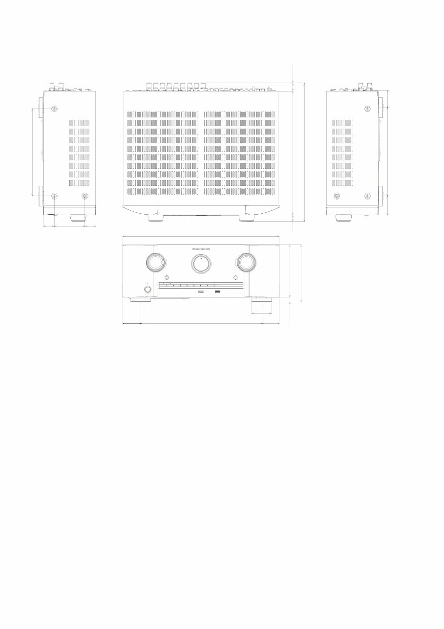
Maximum external dimensions :
440 (W) x 161 (H) x 389 (D) mm
Weight : 11.4 kg
6
DIMENSION
86.0 31.0 31.0
18.0 348.5 22.5
389.0
245.0
248.0 53.5
47.0
440.0
340.0 50.0 50.0
148.0 13.0
161.0
56.0
7
CAUTIONS IN SERVICING
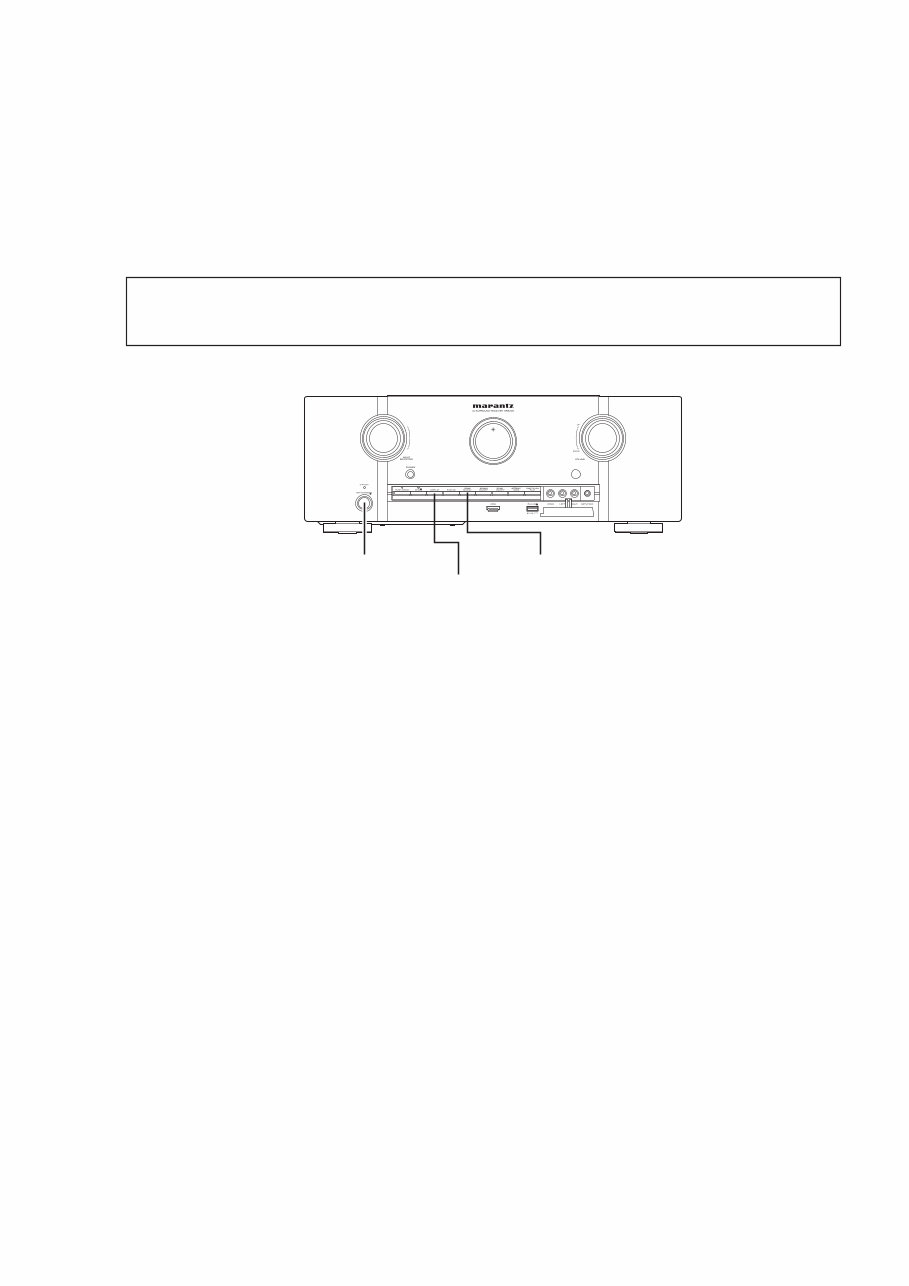
Initializing AV Surround Receiver
AV Surround Receiver initialization should be performed when the μcom, peripheral parts of μcom, and Digital P.W.B.
were replaced.
1. Turn off the power pressing ON/STANDBY button.
2. Press ON/STANDBY button while simultaneously while pressing ZONE SELECT and DISPLAY buttons.
3. Check that the entire display is flashing at intervals of about 1 second, and then release the 2 buttons.
The microprocessor will be initialized.
Service Jig
When you repair the printing board, you can use the following JIG (Extension cable kit).
Please order it from Marantz Official Service Distributor in your region if necessary.
8U-110084S : EXTENSION UNIT KIT : 1 Set
(Refer to 61 page.)
Note: • If step 3 fails, start over from step 1.
• All user settings will be lost and the factory setting will be recovered after the set is initialized.
So make sure to note down your setting beforehand for restoring after the initialization.
ON/STANDBY
DISPLAY
ZONE SELECT
8
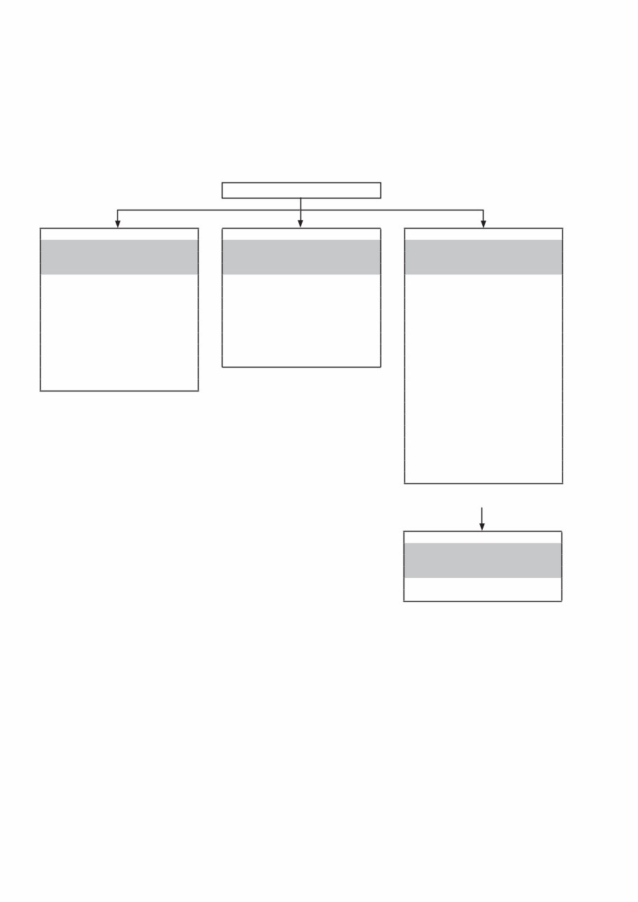
DISASSEMBLY
• Disassemble in order of the arrow in the following figure.
• In the case of the re-assembling, assemble it in order of the reverse of the following flow.
• In the case of the re-assembling, observe "attention of assembling".
• If wire bundles are untied or moved to perform adjustment or replace parts etc., be sure to rearrange them neatly as
they were originally bundled or placed afterward.
Otherwise, incorrect arrangement can be a cause of noise generation.
FRONT PANEL ASSY
Refer to "DISASSEMBLY
1. FRONT PANEL ASSY"
and "EXPLODED VIEW"
PCB FRONT HDMI
(Ref. No. of EXPLODED VIEW : C1)
PCB USB
(Ref. No. of EXPLODED VIEW : C2)
PCB FRONT
(Ref. No. of EXPLODED VIEW : C3)
PCB HP
(Ref. No. of EXPLODED VIEW : C4)
PCB HDMI FFC GUIDE
(Ref. No. of EXPLODED VIEW : C5)
POWER TRANS
Refer to "DISASSEMBLY
4. POWER TRANS"
and "EXPLODED VIEW"
TRANS, POWER
(Ref. No. of EXPLODED VIEW : C12)
CABINET TOP
HEAT SINK ASSY
Refer to "DISASSEMBLY
2. HEAT SINK ASSY"
and "EXPLODED VIEW"
PCB GUIDE L
(Ref. No. of EXPLODED VIEW : C7)
PCB GUIDE R
(Ref. No. of EXPLODED VIEW : C8)
PCB 7CH_AMP ASSY
(Ref. No. of EXPLODED VIEW : C9)
PCB GUIDE TOP
(Ref. No. of EXPLODED VIEW : C10)
HDMI UNIT ASSY
Refer to "DISASSEMBLY
3. HDMI UNIT ASSY"
and "EXPLODED VIEW"
PCB FRONT CNT
(Ref. No. of EXPLODED VIEW : C11)
PCB FUSE
(Ref. No. of EXPLODED VIEW : C14)
PCB SPK_PREOUT
(Ref. No. of EXPLODED VIEW : C15)
PCB SIDE CNT
(Ref. No. of EXPLODED VIEW : C16)
PCB INPUT
(Ref. No. of EXPLODED VIEW : C17)
PCB VIDEO ASSY
(Ref. No. of EXPLODED VIEW : C18)
PCB HDMI
(Ref. No. of EXPLODED VIEW : C19)
PCB RS232C CNT
(Ref. No. of EXPLODED VIEW : C20)
PCB RS232C
(Ref. No. of EXPLODED VIEW : C21)
9
About the photos used for "descriptions of the DISASSEMBLY" section
• The shooting direction of each photograph used herein is indicated on the left side of the respective photograph as
"Shooting direction: ***".
• Refer to the diagram below about the shooting direction of each photograph.
• Photographs with no shooting direction indicated were taken from the top of the set.
The viewpoint of each photograph
(Shooting direction)
[View from the top]
Front side
Shooting direction: B
Shooting direction: D Shooting direction: C
Shooting direction: A
10
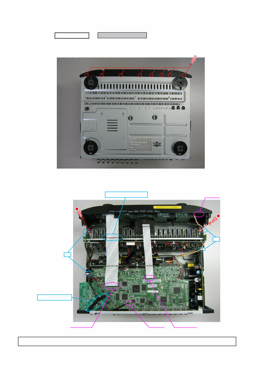
1. FRONT PANEL ASSY
(1) Remove the screws.
(2) Cut the wire clamp bands, then disconnect the connector wires and FFC cables. Remove the screws.
CABINET TOP FRONT PANEL ASSY
→
Proceeding :
View from the bottom
CN390 FFC cable
CN602
FFC cable
STYLE PIN : Loosen
TAPE : Remove
cut
cut
Please refer to "EXPLODED VIEW" for the disassembly method of each P.W.B included in FRONT PANEL ASSY.
You're Reading a Preview
What's Included?
Fast Download Speeds
Online & Offline Access
Access PDF Contents & Bookmarks
Full Search Facility
Print one or all pages of your manual
$36.99
Viewed 74 Times Today


Secure transaction
What's Included?
Fast Download Speeds
Online & Offline Access
Access PDF Contents & Bookmarks
Full Search Facility
Print one or all pages of your manual
$36.99
This service and repair manual for the Marantz SR6006 Audio/Video Surround Receiver is an essential resource for both professional mechanics and DIY enthusiasts. It contains comprehensive technical information required for servicing and repairing the receiver, ensuring optimal performance.
- Servicing Safety and Precautions
- Installation Instructions
- Test and Service Modes
- Diagnostics & Troubleshooting
- Disassemble and Assembly Instructions
- Adjustment Procedure
- Firmware Update Procedure
- Level Diagram
- Block Diagram
- Power Diagram
- Wiring Diagram
- Printed Circuit Boards
- Schematic Diagrams
- Semiconductors
- Exploded Views
- Replacement Parts List
This official service manual is provided in high resolution format, ensuring clarity and precision. It offers instant access after payment, allowing for quick initiation of repairs. The manual is available in English and consists of 224 pages, delivering detailed insights into the receiver's technical specifications and maintenance procedures.


