


MODEL JP E3 E2 EK EA E1 E1K E1C
AVR-E400 P
AVR-X2000 P P P P
INTEGRATED NETWORK AV RECEIVER
S0676-0V04DM/DG1305
Ver. 4
• Please use this service manual with referring to the operating instructions without fail.
• Some illustrations using in this service manual are slightly different from the actual set.
• For purposes of improvement, specifications and design are subject to change without notice.
• Cautions when replacing the FRONT PANEL(Only AVR-X2000E3):Depending on when the model was
manufactured, there may be washers in the FRONT PANEL screw positions. Washers are not used in the
replacement FRONT PANEL.If you are replacing a FRONT PANEL that has washers, discard the washers.
Please refer to the
MODIFICATION NOTICE. e
SERVICE MANUAL
e
D&M Holdings Inc.
Copyright 2013 D&M Holdings Inc. All rights reserved.
WARNING: Violators will be prosecuted to the maximum extent possible.
Downloaded from www.Manualslib.com manuals search engine

ABOUT THIS MANUAL .............................................................3
What you can do with this manual ............................................3
Using Adobe Reader (Windows version) ..................................4
SAFETY PRECAUTIONS ..........................................................6
NOTE FOR SCHEMATIC DIAGRAM.........................................7
NOTE FOR PARTS LIST ...........................................................7
TECHNICAL SPECIFICATIONS ................................................9
DIMENSION .............................................................................10
CAUTION IN SERVICING........................................................ 11
Initializing INTEGRATED NETWORK AV RECEIVER ............ 11
Service Jig .............................................................................. 11
DISASSEMBLY ........................................................................12
1. FRONT PANEL ASSY ........................................................14
2. PCB MX PORT/PCB RS232C (AVR-X2000E3 only) ........15
3. PCB HDMI..........................................................................16
4. POWER TRANS MAIN ......................................................17
5. PCB VIDEO ASSY .............................................................17
6. PCB SMPS.........................................................................18
7. RADIATOR ASSY...............................................................20
SPECIAL MODE .....................................................................22
Special mode setting button (for E400E3 model)....................22
Special mode setting button (for X2000 model) ......................23
1. µcom/DSP Version display mode .......................................24
2. PANEL/REMOTE LOCK Selection mode...........................28
3. Service Related Selection mode ........................................29
BLOCK DIAGRAM...................................................................32
4. Protection Pass mode ........................................................49
5. DM860A Reboot mode.......................................................49
6. Remote ID Setup mode......................................................50
7. NETWORK Initialization mode ...........................................50
JIG FOR SERVICING ..............................................................52
WHEN THE MICROPROCESSOR IS REPLACED WITH A
NEW ONE ...............................................................................55
PROCEDURE FOR UPGRADING THE VERSION OF
THE FIRMWARE.....................................................................55
1. How to update by DFW......................................................55
2. How to update by DPMS....................................................59
3. How to update by USB Memory.........................................66
ADJUSTMENT .........................................................................74
TROUBLE SHOOTING ............................................................82
1. POWER..............................................................................82
2. Analog video ......................................................................83
3. HDMI/DVI ...........................................................................87
4. AUDIO................................................................................89
5. Network/USB......................................................................92
6. SMPS .................................................................................95
CLOCK FLOW & WAVE FORM IN DIGITAL BLOCK
DIAGRAM ................................................................................98
LEVEL DIAGRAM....................................................................99
BLOCK DIAGRAM.................................................................105
POWER DIAGRAM................................................................106
WIRING DIAGRAM ................................................................107
PRINTED WIRING BOARDS.................................................108
SCHEMATIC DIAGRAMS (1/24) ........................................... 119
FRONT UNIT (1/1) ................................................................ 119
INPUT UNIT (1/1) ..................................................................120
SMPS UNIT (1/1) ..................................................................121
VIDEO UNIT (1/3) .................................................................122
VIDEO UNIT (2/3) .................................................................123
VIDEO UNIT (3/3) .................................................................124
AMP UNIT (1/2) .....................................................................125
AMP UNIT (2/2) .....................................................................126
MAIN UNIT (1/2)....................................................................127
MAIN UNIT (2/2)....................................................................128
HDMI UNIT (1/13) .................................................................129
HDMI UNIT (2/13) .................................................................130
HDMI UNIT (3/13) .................................................................131
HDMI UNIT (4/13) .................................................................132
HDMI UNIT (5/13) .................................................................133
HDMI UNIT (6/13) .................................................................134
HDMI UNIT (7/13) .................................................................135
HDMI UNIT (8/13) .................................................................136
HDMI UNIT (9/13) .................................................................137
HDMI UNIT (10/13) ...............................................................138
HDMI UNIT (10/13) ...............................................................139
HDMI UNIT (11/13)................................................................140
HDMI UNIT (12/13) ...............................................................141
HDMI UNIT (13/13) ...............................................................142
EXPLODED VIEW .................................................................143
PARTS LIST OF EXPLODED VIEW......................................145
PACKING VIEW .....................................................................146
PARTS LIST OF PACKING & ACCESSORIES ....................147
SEMICONDUCTORS .............................................................148
1. IC's ...................................................................................148
2. FL DISPLAY .....................................................................170
CONTENTS
2
Downloaded from www.Manualslib.com manuals search engine
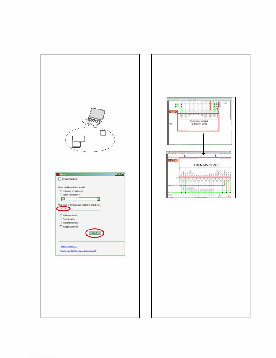
Jump to the target of a schematic
diagram connector
Click the Ref. No. of the target connector in the red
box around a schematic diagram connector.
•The screen jumps to the target connector.
•Page magnification stays the same as before the
jump.
CP401
CP106
v
ABOUT THIS MANUAL
Read the following information before using the service manual.
What you can do with this manual
Search for a Ref. No. (phrase)
(Ctrl+Shift+F)
You can use the search function in Acrobat Reader to
search for a Ref. No. in schematic diagrams, printed
wiring board diagrams, block diagrams, and parts
lists.
1.Press Ctrl+Shift+F on the keyboard.
• The Search window appears.
2.Enter the Ref. No. you want to search for in the
Search window, and then click the Search button.
•A list of search results appears.
3.Click an item on the list.
• The screen jumps to the page for that item, and the
search phrase is displayed.
Ctrl
Shift
F
3
Downloaded from www.Manualslib.com manuals search engine
Using Adobe Reader (Windows version)
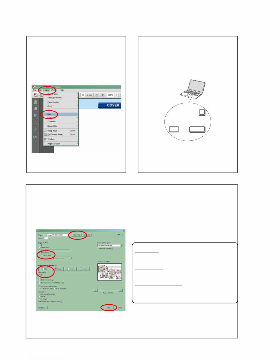
• Properties
Click this button and check that the printer is set to a
suitable paper size.
• Page to print
Select the following checkbox.
"More Options" : "Current View"
• Page Sizing & Handling
Select the following checkbox.
"Size" / "Size Options" : "Fit"
Add notes to this data (Sign)
The Sign function lets you add notes to the data in
this manual.
Save the file once you have finished adding notes.
[Example using Adobe Reader X]
On the "View" menu, click "Sign".
• The Sign pane appears.
[Example using Adobe Reader 9]
On the "Document" menu, click "Sign".
Magnify schematic / printed wiring
board diagrams - 1
(Ctrl+Space, mouse operation)
Press Ctrl+Space on the keyboard and drag the
mouse to select the area you want to view.
• The selected area is magnified.
• When you want to move the area shown, hold
down Space and drag the mouse.
• When you want to show a full page view, press
Ctrl+0 on the keyboard.
Ctrl Space
0
Print a magnified part of the manual
The Properties dialog box and functions will vary depending on your printer.
1. Drag the mouse to magnify the part you want to print.
2. On the "File" menu, click "Print".
3. Configure the following settings in the Print dialog box.
4. Click the Print button to start printing.
4
Downloaded from www.Manualslib.com manuals search engine
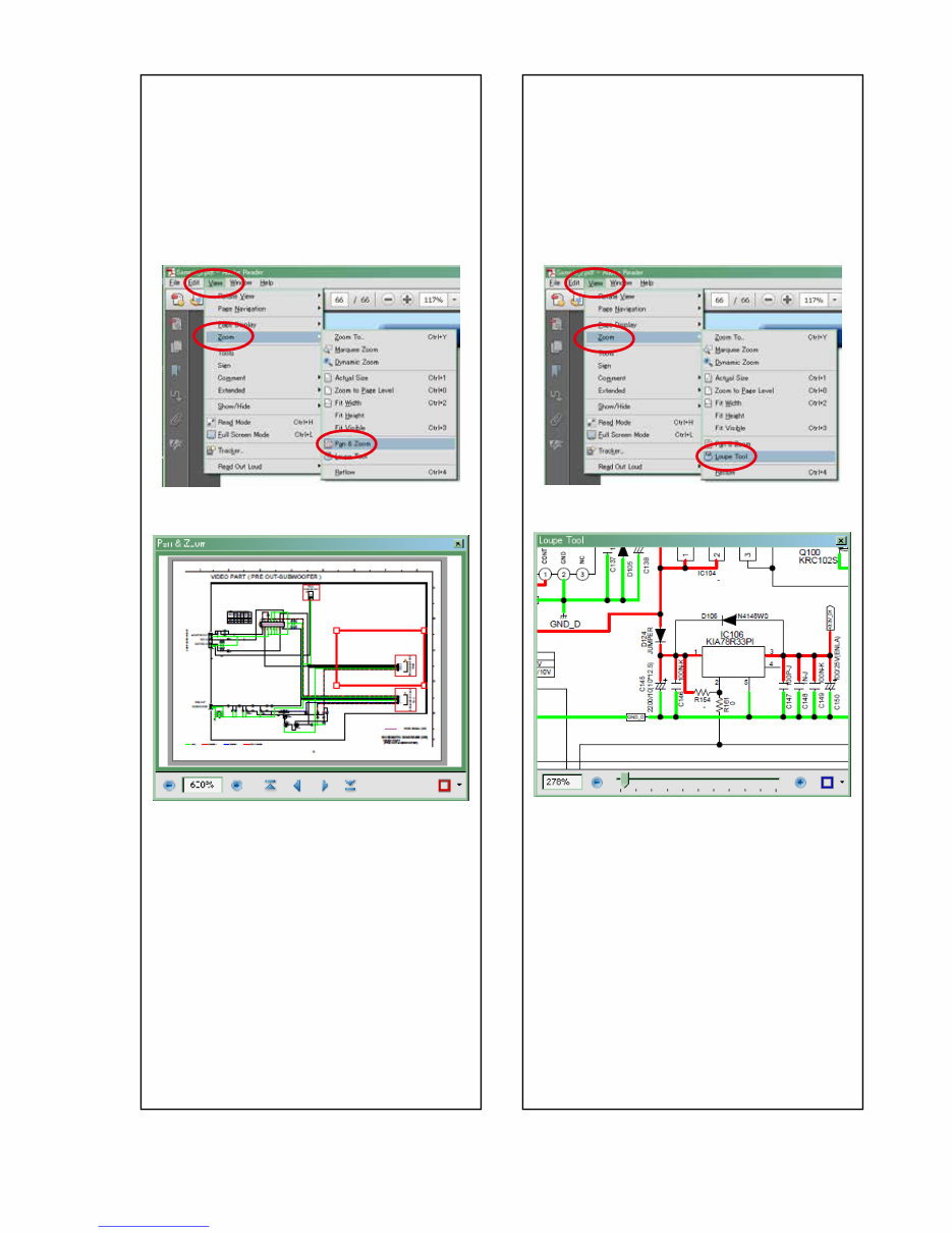
Magnify schematic / printed wiring
board diagrams - 2
(Pan & Zoom function)
The Pan & Zoom function lets you see which part of
a magnified diagram is being shown in a separate
window.
[Example using Adobe Reader X]
On the "View" menu, point to "Zoom", and then click
"Pan & Zoom".
• The Pan & Zoom window appears on the screen.
[Example using Adobe Reader 9]
On the "Tools" menu, point to "Select & Zoom", and
then click "Pan & Zoom Window".
Magnify schematic / printed wiring
board diagrams - 3
(Loupe Tool function)
The Loupe Tool function lets you magnify a specific
part of a diagram in a separate window.
[Example using Adobe Reader X]
On the "View" menu, point to "Zoom", and then click
"Loupe Tool".
• The Loupe Tool window appears on the screen.
[Example using Adobe Reader 9]
On the "Tools" menu, point to "Select & Zoom", and
then click "Loupe Tool Window".
5
Downloaded from www.Manualslib.com manuals search engine
SAFETY PRECAUTIONS
The following items should be checked for continued protection of the customer and the service technician.
leakage current check
Before returning the set to the customer, be sure to carry out either (1) a leakage current check or (2) a line to chassis
resistance check. If the leakage current exceeds 0.5 milliamps, or if the resistance from chassis to either side of the
power cord is less than 460 kohms, the set is defective.
Be sure to test for leakage current with the AC plug in both polarities, in addition, when the set's power is in each state
(on, off and standby mode), if applicable.
CAUTION Please heed the following cautions and instructions during servicing and
inspection.
◎ Heed the cautions!
Cautions which are delicate in particular for servicing
are labeled on the cabinets, the parts and the chassis,
etc. Be sure to heed these cautions and the cautions
described in the handling instructions.
◎ Cautions concerning electric shock!
(1) An AC voltage is impressed on this set, so if you
touch internal metal parts when the set is energized,
you may get an electric shock. Avoid getting an
electric shock, by using an isolating transformer
and wearing gloves when servicing while the set is
energized, or by unplugging the power cord when
replacing parts, for example.
(2) There are high voltage parts inside. Handle with
extra care when the set is energized.
◎ Caution concerning disassembly and
assembly!
Through great care is taken when parts were
manufactured from sheet metal, there may be burrs on
the edges of parts. The burrs could cause injury if fingers
are moved across them in some rare cases. Wear gloves
to protect your hands.
◎ Use only designated parts!
The set's parts have specific safety properties (fire
resistance, voltage resistance, etc.). Be sure to use parts
which have the same properties for replacement. The
burrs have the same properties. In particular, for the
important safety parts that are indicated by the z mark
on schematic diagrams and parts lists, be sure to use
the designated parts.
◎ Be sure to mount parts and arrange the wires
as they were originally placed!
For safety seasons, some parts use tapes, tubes or other
insulating materials, and some parts are mounted away
from the surface of printed circuit boards. Care is also
taken with the positions of the wires by arranging them
and using clamps to keep them away from heating and
high voltage parts, so be sure to set everything back as
it was originally placed.
◎ Make a safety check after servicing!
Check that all screws, parts and wires removed or
disconnected when servicing have been put back in their
original positions, check that no serviced parts have
deteriorate the area around. Then make an insulation
check on the external metal connectors and between
the blades of the power plug, and otherwise check that
safety is ensured.
(Insulation check procedure)
Unplug the power cord from the power outlet, disconnect
the antenna, plugs, etc., and on the power. Using a 500V
insulation resistance tester, check that the insulation
resistance value between the inplug and the externally
exposed metal parts (antenna terminal, headphones
terminal, input terminal, etc.) is 1MΩ or greater. If it is
less, the set must be inspected and repaired.
Many of the electric and the structural parts used in the
set have special safety properties. In most cases these
properties are difficult to distinguish by sight, and the use
of replacement parts with higher ratings (rated power
and withstand voltage) does not necessarily guarantee
that safety performance will be preserved. Parts with
safety properties are indicated as shown below on the
wiring diagrams and the parts list in this service manual.
Be sure to replace them with the parts which have the
designated part number.
(1) Schematic diagrams.......Indicated by the z mark.
(2) Parts lists.......Indicated by the z mark.
The use of parts other than the
designated parts could cause electric
shocks, fires or other dangerous
situations.
CAUTION Concerning important
safety parts
6
Downloaded from www.Manualslib.com manuals search engine
NOTE FOR SCHEMATIC DIAGRAM
WARNING:
Parts indicated by the z mark have critical characteristics. Use ONLY replacement parts recommended by the manufacturer.
CAUTION:
Before returning the set to the customer, be sure to carry out either (1) a leakage current check or (2) a line to chassis resistance check. If
the leakage current exceeds 0.5 milliamps, or if the resistance from chassis to either side of the power cord is less than 460 kohms, the set
is defective.
WARNING:
DO NOT return the set to the customer unless the problem is identified and remedied.
NOTICE:
ALL RESISTANCE VALUES IN OHM. k=1,000 OHM / M=1,000,000 OHM
ALL CAPACITANCE VALUES ARE EXPRESSED IN MICRO FARAD, UNLESS OTHERWISE INDICATED. P INDICATES MICRO-MICRO
FARAD. EACH VOLTAGE AND CURRENT ARE MEASURED AT NO SIGNAL INPUT CONDITION. CIRCUIT AND PARTS ARE SUBJECT
TO CHANGE WITHOUT PRIOR NOTICE.
Parts indicated by "nsp" on this table cannot be supplied.
When ordering a part, make a clear distinction between "1" and "I" (i) to avoid mis-supplying.
A part ordered without specifying its part number can not be supplied.
General-purpose Carbon Chip Resistors are not included are not included in the P.W.Board parts list.
(Refer to the Schematic Diagram for those parts.)
Parts indicated by the z mark have critical characteristics. Use ONLY replacement parts recommended by the manufacturer.
General-purpose Carbon Film Resistor in the P.W.Board parts list. (Refer to the Schematic Diagram for those parts.)
Part indicated by "★" mark is not illustrated in the exploded view.
WARNING:
1.
2.
3.
4.
5.
6.
NOTE FOR PARTS LIST
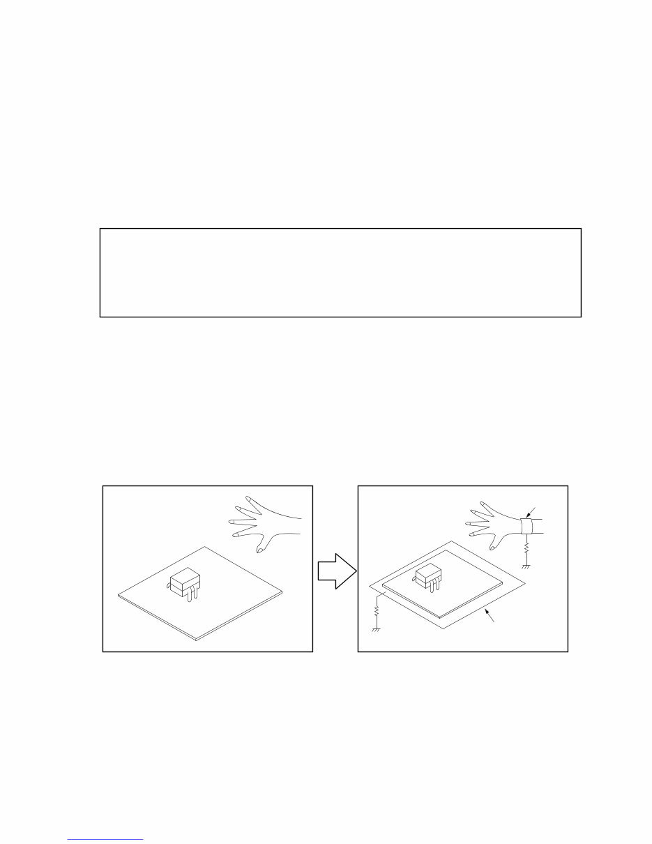
INSTRUCTIONS FOR HANDLING SEMI-CONDUCTORS AND OPTICAL UNIT
Electrostatic breakdown of the semi-conductors or optical pickup may occur due to a potential difference caused by
electrostatic charge during unpacking or repair work.
1. Ground for Human Body
Be sure to wear a grounding band (1 MΩ) that is properly grounded to remove any static electricity that may be
charged on the body.
2. Ground for Workbench
Be sure to place a conductive sheet or copper plate with proper grounding (1 MΩ) on the workbench or other surface,
where the semi-conductors are to be placed. Because the static electricity charge on clothing will not escape through
the body grounding band, be careful to avoid contacting semi-conductors with your clothing
<Incorrect>
CBA
Grounding Band
Conductive Sheet or
Copper Plate
1MΩ
1MΩ
<Correct>
CBA
7
Downloaded from www.Manualslib.com manuals search engine

Personal notes:
8
Downloaded from www.Manualslib.com manuals search engine

n Audio section
• Power amplifier
Rated output(for E400 model):
Front:
90 W + 90 W (8 Ω/ohms, 20 Hz – 20 kHz with 0.08 % T.H.D.)
125 W + 125 W (6 Ω/ohms, 1 kHz with 0.7 % T.H.D.)
Center:
90 W (8 Ω/ohms, 20 Hz – 20 kHz with 0.08 % T.H.D.)
125 W (6 Ω/ohms, 1 kHz with 0.7 % T.H.D.)
Surround:
90 W + 90 W (8 Ω/ohms, 20 Hz – 20 kHz with 0.08 % T.H.D.)
125 W + 125 W (6 Ω/ohms, 1 kHz with 0.7 % T.H.D.)
Surround back:
90 W + 90 W (8 Ω/ohms, 20 Hz – 20 kHz with 0.08 % T.H.D.)
125 W + 125 W (6 Ω/ohms, 1 kHz with 0.7 % T.H.D.)
Rated output(for X2000 model):
Front:
90 W + 90 W (8 Ω/ohms, 20 Hz – 20 kHz with 0.08 % T.H.D.)
125 W + 125 W (6 Ω/ohms, 1 kHz with 0.7 % T.H.D.)
Center:
90 W (8 Ω/ohms, 20 Hz – 20 kHz with 0.08 % T.H.D.)
125 W (6 Ω/ohms, 1 kHz with 0.7 % T.H.D.)
Surround:
90 W + 90 W (8 Ω/ohms, 20 Hz – 20 kHz with 0.08 % T.H.D.)
125 W + 125 W (6 Ω/ohms, 1 kHz with 0.7 % T.H.D.)
Surround back:
90 W + 90 W (8 Ω/ohms, 20 Hz – 20 kHz with 0.08 % T.H.D.)
125 W + 125 W (6 Ω/ohms, 1 kHz with 0.7 % T.H.D.)
Output connectors: 6 – 16 Ω/ohms
• Analog
Input sensitivity/Input impedance: 200 mV/47 kΩ/kohms
Frequency response: 10 Hz – 100 kHz — +1, –3 dB (DIRECT mode)
S/N : 100 dB (IHF–A weighted, DIRECT mode)
n Tuner section
(Note: μV at 75 Ω/ohms, 0 dBf = 1 x 10–15 W)
Receiving Range: FM 87.5 MHz – 107.9 MHz(for E400 model)
AM 520 kHz – 1710 kHz(for E400 model)
FM 87.50 MHz – 108.00 MHz(for X2000 model)
AM 522 kHz – 1611 kHz(for X2000 model)
Usable Sensitivity: FM 1.2 μV (12.8 dBf)
AM 18 μV
50 dB Quieting
Sensitivity:
MONO 2.8 μV (20.2 dBf)
S/N : MONO 70 dB (IHF–A weighted, DIRECT mode)
STEREO 67 dB (IHF–A weighted, DIRECT mode)
Total harmonic
Distortion:
MONO 0.7 % (1 kHz)
STEREO 1.0 % (1 kHz)
n General
Power supply: AC 120 V, 60 Hz
AC 230 V, 50/60 Hz
Power consumption: 460 W
Power consumption in standby mode: 0.1 W
Power consumption in CEC standby mode:0.5 W
Power consumption in network standby mode: 2.7 W
TECHNICAL SPECIFICATIONS
9
Downloaded from www.Manualslib.com manuals search engine
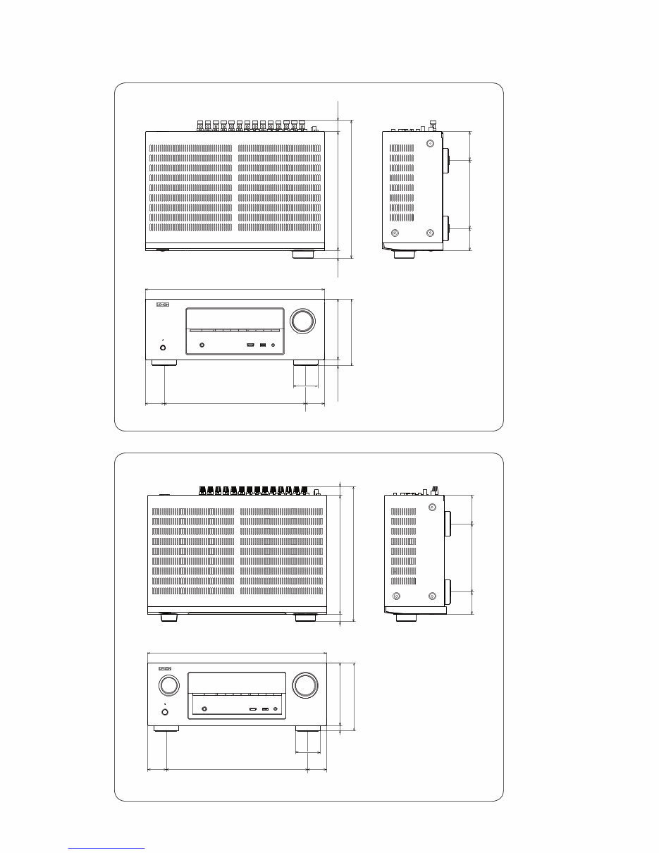
Unit : in. (mm)
11 11/32 (288.0)
12 63/64 (330.0
)
6 15/32 (164.5)
2 1/8
(54.0)
2 47/64
(69.5)
37/64 (14.5
) 6 (152.5)
6 67/64 (167.0)
17 3/32 (434.0)
13 35/64 (344.0)
2 23/64
(60.0)
1 49/64
(45.0)
1 49/64
(45.0)
47/64
(18.5)
59/64
(23.5)
Weight : 20 lbs 15 oz (9.5 kg)
Unit : in. (mm)
11 11/32 (288.0)
13 5/32 (334.0)
6 15/32 (164.5)
2 1/8
(54.0)
2 47/64
(69.5)
37/64 (14.5)
5 13/16 (147.5)
6 3/8 (162.0)
17 3/32 (434.0)
13 35/64 (344.0)
2 23/64
(60.0)
1 49/64
(45.0)
1 49/64
(45.0)
47/64
(18.5)
1 5/64
(27.5)
Weight : 20 lbs 12 oz (9.4 kg)
[AVR-E400 model]
[AVR-X2000 model]
DIMENSION
10
Downloaded from www.Manualslib.com manuals search engine
You're Reading a Preview
What's Included?
 Lifetime Access
Fast Download Speeds
Online & Offline Access
Access PDF Contents & Bookmarks
Full Search Facility
Print one or all pages of your manual
$35.99
Denon AVR-E400 / AVR-X2000 AV Receiver Service & Repair Manual
Viewed 58 Times Today

What's Included?
Lifetime Access
Fast Download Speeds
Online & Offline Access
Access PDF Contents & Bookmarks
Full Search Facility
Print one or all pages of your manual
$35.99

Secure transaction
What's Included?
Lifetime Access
Fast Download Speeds
Online & Offline Access
Access PDF Contents & Bookmarks
Full Search Facility
Print one or all pages of your manual
Description
The Denon AVR-E400 / AVR-X2000 AV Receiver Service & Repair Manual is a comprehensive guide designed for both professional mechanics and DIY enthusiasts. This manual, available in English, spans 196 pages and is compatible with Windows and Mac platforms.
- Language: English
- Pages: 196
- Format: PDF
- Platform: Windows and Mac


