

PIONEER PL-A25 OPERATING Owners Manual
What's Included?
Fast Download Speeds
Online & Offline Access
Access PDF Contents & Bookmarks
Full Search Facility
Print one or all pages of your manual
NEe R"
BRAND IN HI·FI REPR O DU C TI ON
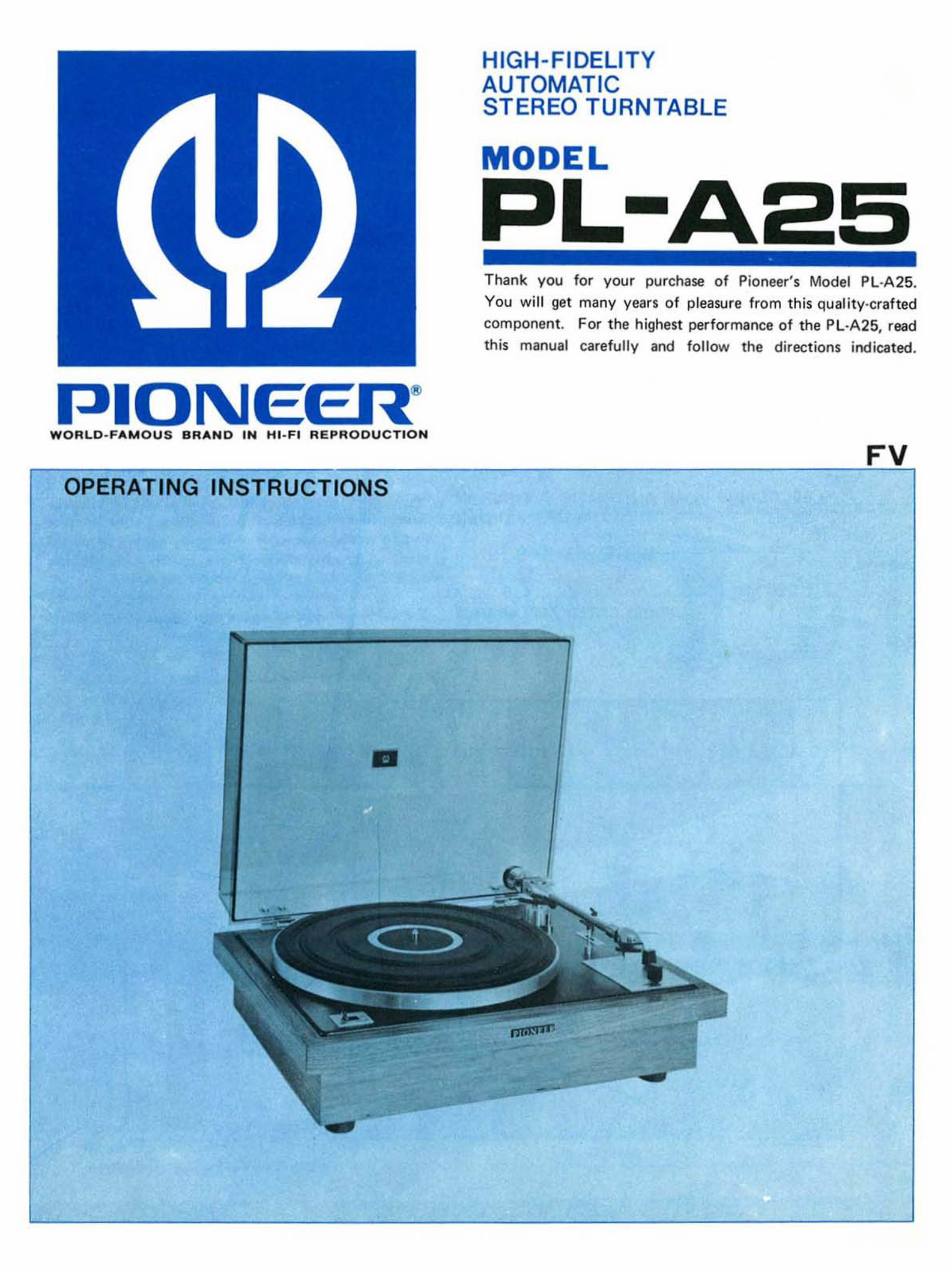
OPERATING INSTRUCTIONS
•
HIGH-FIDELITY
AUTOMATIC
STEREO TURNTABLE
ODEL
Thank you for your purchase of Pioneer's Model PL- A2 5.
You will get ma ny years of pleasure from th is quality-crafted
component. For t he highest performance of t he PL·A25, read
this manual carefully and follow the directions indica ted .
FV
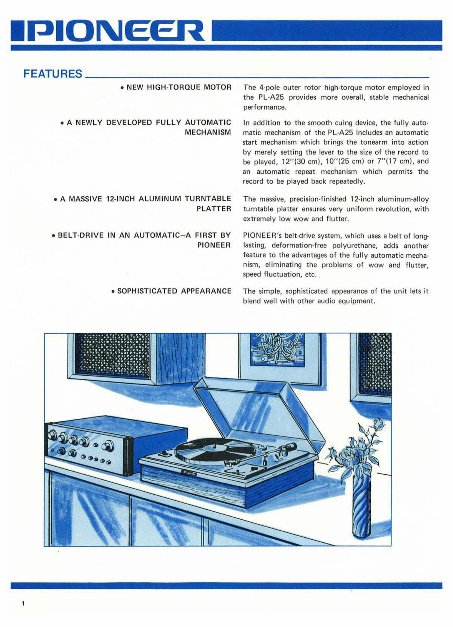
FEATURES __________________________________________ ___
I
• NEW HIGH-TORQUE MOTOR The 4-pole outer rotor high-torque mot or employed in
the PL-A25 provides more overall, stable mechanical
performance.
• A NEWLY DEVELOPED FULLY AUTOMATIC
MECHANISM
In addition to the smooth cu ing device, the fully au t o-
matic mechanism of the PL-A25 includes an aut omatic
start mechanism which brings the tonearm i nto action
by merely setting the lever to the size of the record to
be played, 1 2"(30 em). 10"(25 em) or 7"(17 em), and
an automatic repeat mechanism which permits the
record to be played back repeatedly .
• A MASSIVE 12·INCH ALUMINUM TURNTABLE The massive. precision-finished 12- inch aluminum-alloy
PLATTER tur nt able platter ensures very uniform revolution. with
extremely l ow wow and flutter.
• BEL T·DRIVE IN AN AUTOMATIC- A FIRST BY
PIONEER
PI ONEER's belt-drive system, which uses a belt of long-
las tin g, deformation-free polyurethane, adds another
feature to the advantages of the fully automatic mecha·
nism, el iminating the problems of wow and flutter,
speed fluctuation, etc_
• SOPHISTICATED APPEARANCE The simple, sophisticated appearance of the unit lets it
blend well with other audio equipment.
•
INSTALLATION _ _ __ ___ ____________ _
The Model Pl·A25 operates witt'! a very smalt tracking
force. Select the location of the PL ·A25 with care. It
should be in a stable position. It is a good practice to
keep the unit away from the loudspeaker cabi nets as far
as possible.
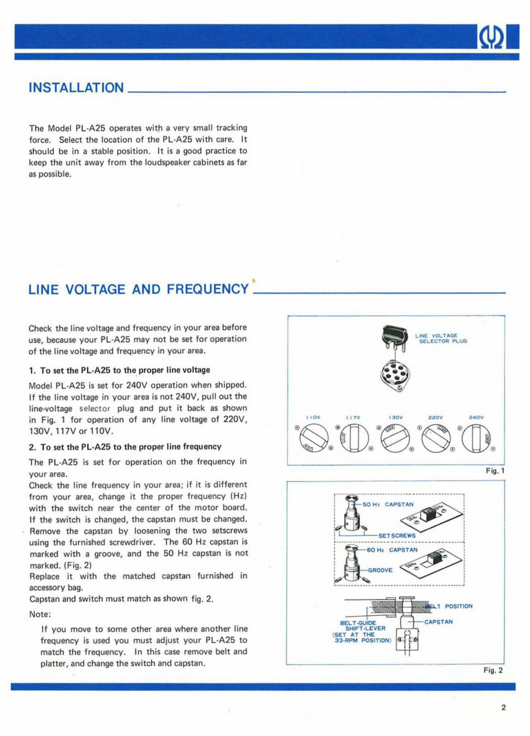
LINE VOLTAGE AND FREQUENCY _ _______ ____ _
Check the line voltage and frequency in your area before
use, because your PL ·A25 may not be set for operation
of the line vol tage and frequency in your area.
1. To set the PL·A25 to the, pr oper lin e vo ltage
Model PL ·A 25 is se t for 240V operation when shipped.
If the line voltage in your area is not 240V. pull out the
line-voltage selector plug and put it back as shown
in Fig. 1 for operation of any li ne voltage of 220V,
130V, 117Vor110V.
2. To set the Pl ·A25 to th e proper line frequency
The Pl·A25 is set for operat i on on the frequency in
your area.
Check the line frequency in your area; if it is different
from your area, change it the proper frequency ( Hz )
with the switch near the center of the motor board .
1f the switch is ch anged, the capstan must be changed.
Remove the capstan by loosening the two setscrews
using the furnished screwdriver. The 60 Hz capstan is
marked with a groove, and the 50 Hz capstan is not
marked. (Fig. 2)
Replace it with the matched capstan furnis hed in
accessory bag.
Capstan and switch must match as shown fig. 2.
Note:
If you move to some other area where another line
frequency is used you must adjust your Pl ·A25 to
match the frequency . In this case remove belt and
platter, and change the switch and capstan.
I , 0",
I ,TV
o
'- " H.
. ..
LINE; YOL T .... GE
SI!. .I!:(; TOR P\..UG
220",
CAPSTAN
( SET AT T HE
33 ·_ POSITION)
POSIT ION
•
F ig. 1
Fig. 2
2
3
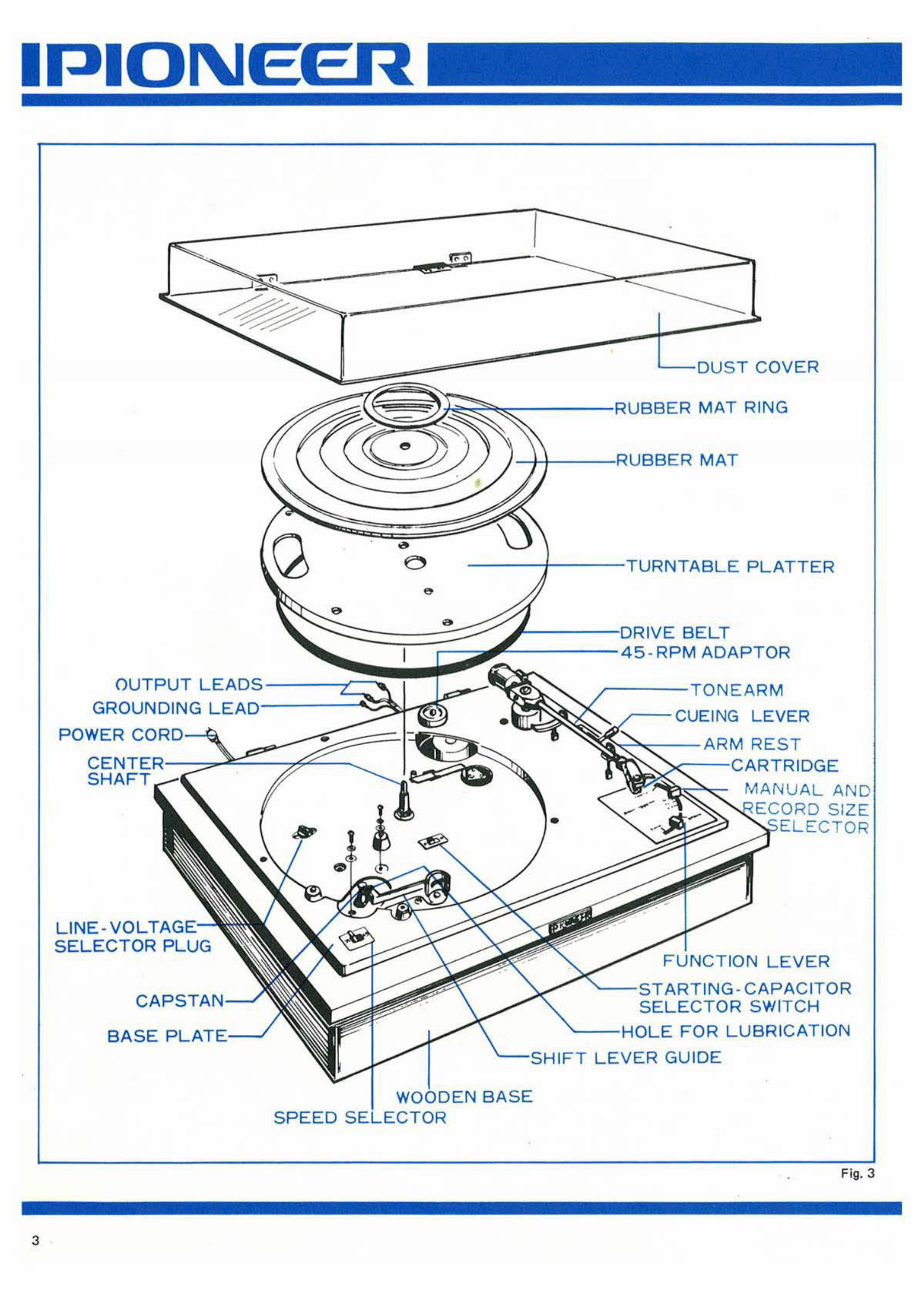
OUTPUT
GROUNDING
POWER CC
LINE -VO L
5ELECTOR PLUG
CAPS
EIR
SPEED
COVER
MAT RING
MAT
NTAB LE PLATTER
I VE BELT
5- RPM ADAPTDR
M
CUEING LEVER
M RE ST
ARTRIDGE
MAN UAL AND
SI ZE
TO R
FUN CTION LEVER
ARTING -C APA CITOR
SWITCH
FOR LUBRICATION
1FT LEVER GUIDE
-
Fig. 3
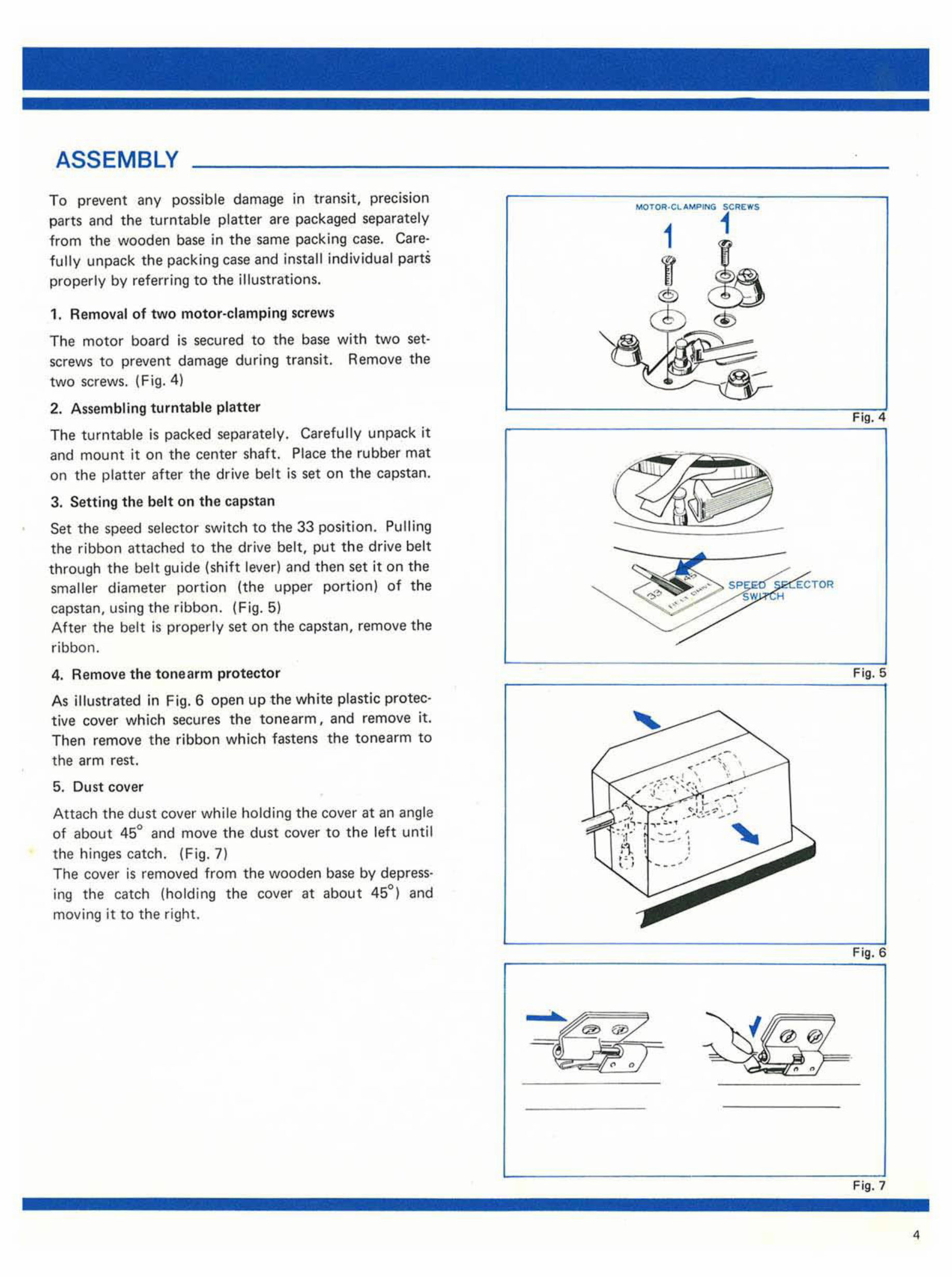
ASSEMBLY
To prevent any possible damage in tr ansit, precIsion
parts and the turntable platter are packaged separately
from the wooden base in the same packing case. Ca re-
fully unpack the packing case and install individual parts
properly by referring to the illustrations.
1. Remo va l of two motor-clamp ing screws
The motor board is secured to the base with two set·
screws to prevent damage during transit. Remove the
two sc rews. (Fig. 4)
2. As sembling turntable platter
The turntable is packed separately. Ca refully unpack it
and mount it on the center shaft. Pl ace the rubber mat
on the platter after the drive b el t is set on the capstan.
3. Setting the belt on the capstan
Set the speed sele cto r switch to the 33 position. Pulling
the ribbon a tta ched to the drive belt, put the drive belt
through the bel t gu ide (shift lever) and then set it on the
smaller diameter po rt io n (the upper portion) of the
capstan, using the ribbon. (F ig. 5)
After the belt is properly set on th e capstan, remove the
ribbon.
4. Remove the tone arm pro tec t or
As illustrated in Fig. 6 open up the white plastic protec-
tive cover which secures the ton earm, and remove it.
Then remove th e ribbon which fastens the tonearm to
the arm rest.
5. Dust cover
Attach the dust cover whi le holding the cover at an angle
of about 45° and move the du st cover to the left until
the hinges catch. (Fig.7)
The cover is removed from the wooden base by depress·
ing the catch (holding th e cover at ab out 45°) and
moving it to the right.
5<; REIfI'S
1
1
®
Fi g. 4
-
Fig. 5
Fig. 6
Fi g, 7
4
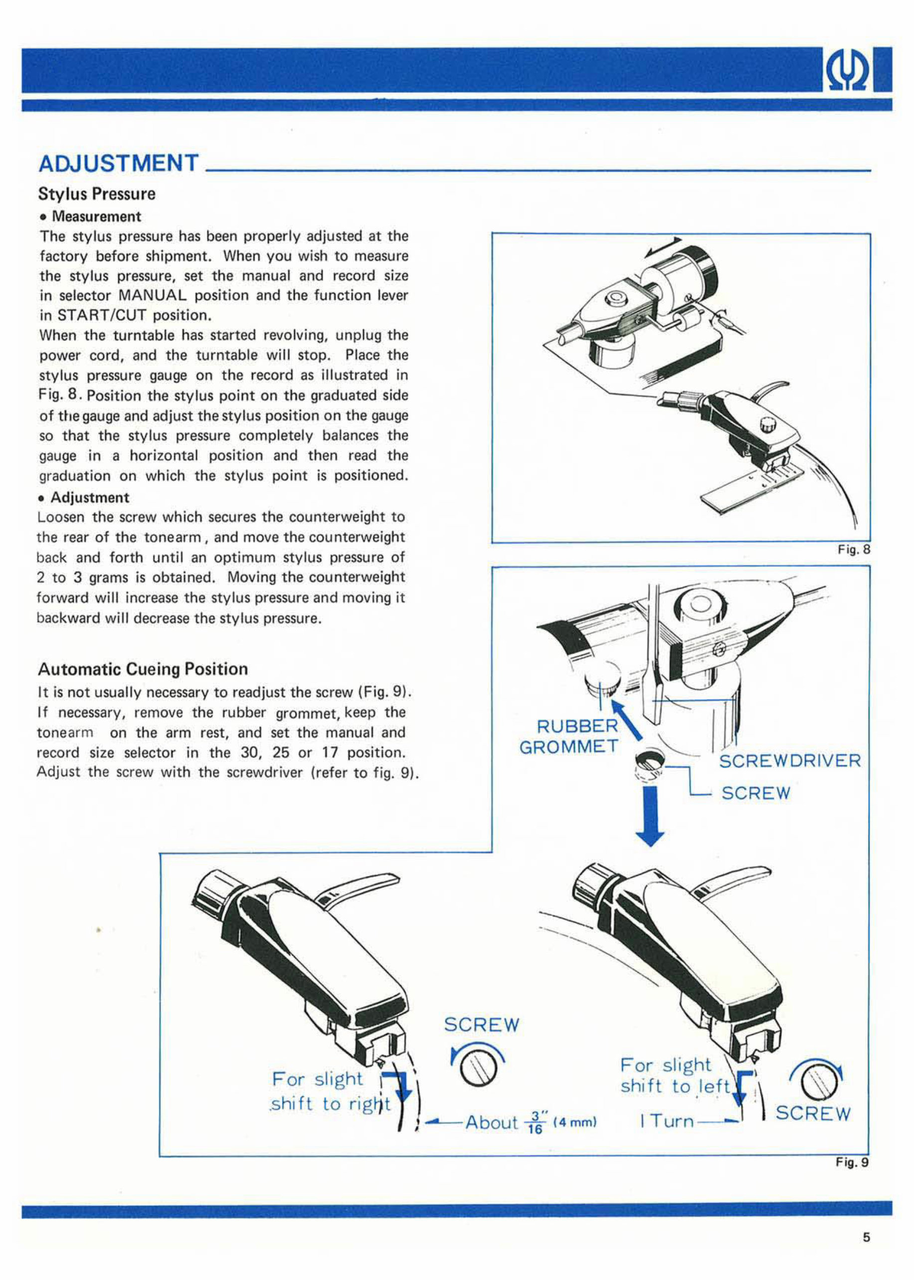
AOUUSTMENT ______________________________________ __
Stylus Pressure
• Measurement
The stylus pre ssu re has been properly adjusted at the
fa cto ry before shipment. When you wish to measure
the sty lu s pressure, set the manual and record size
in selector MANUAL position and the function lever
in STA RT /CUT position.
When the tu rnt able has started revolving, unplug the
power cord, and the turntable will stop. Place the
stylus pr ess ure gauge on the record as illustrated in
Fig . 8. Position the stylus point on the graduated side
of the gauge and adjust the stylus position on the gauge
so that the stylus pressure complete ly balances the
gauge in a hori zo ntal position and th en re ad the
graduation on which the stylus po int is positioned .
• Adjustment
Loosen the screw which secures the counterweig ht to
the rear of the t onearm, and move th e counterweight
back and forth until an optimum stylus pressure of
2 to 3 grams is obtained. Moving the counte rweight
forward will increase the stylus pressure and moving it
backward will decrease the stylus pressure.
Automatic Cu e ing Position
It is not usually necessary to readjust the screw (F ig. 9 ).
If necessary, remove the rubber grommet, keep the
tone arm on the arm rest, and set the manual and
record size selector in the 30, 25 or 17 position.
Adjust th e screw with the screwdriver (refer to fig. 9).
•
,
RUBBER
SCREW
'®'
1 f ( 4mm )
Fig .8
SC REW
For slight
shift to
I Turn- -'
f@
S CREW
Fig . 9
5
6
NEIR
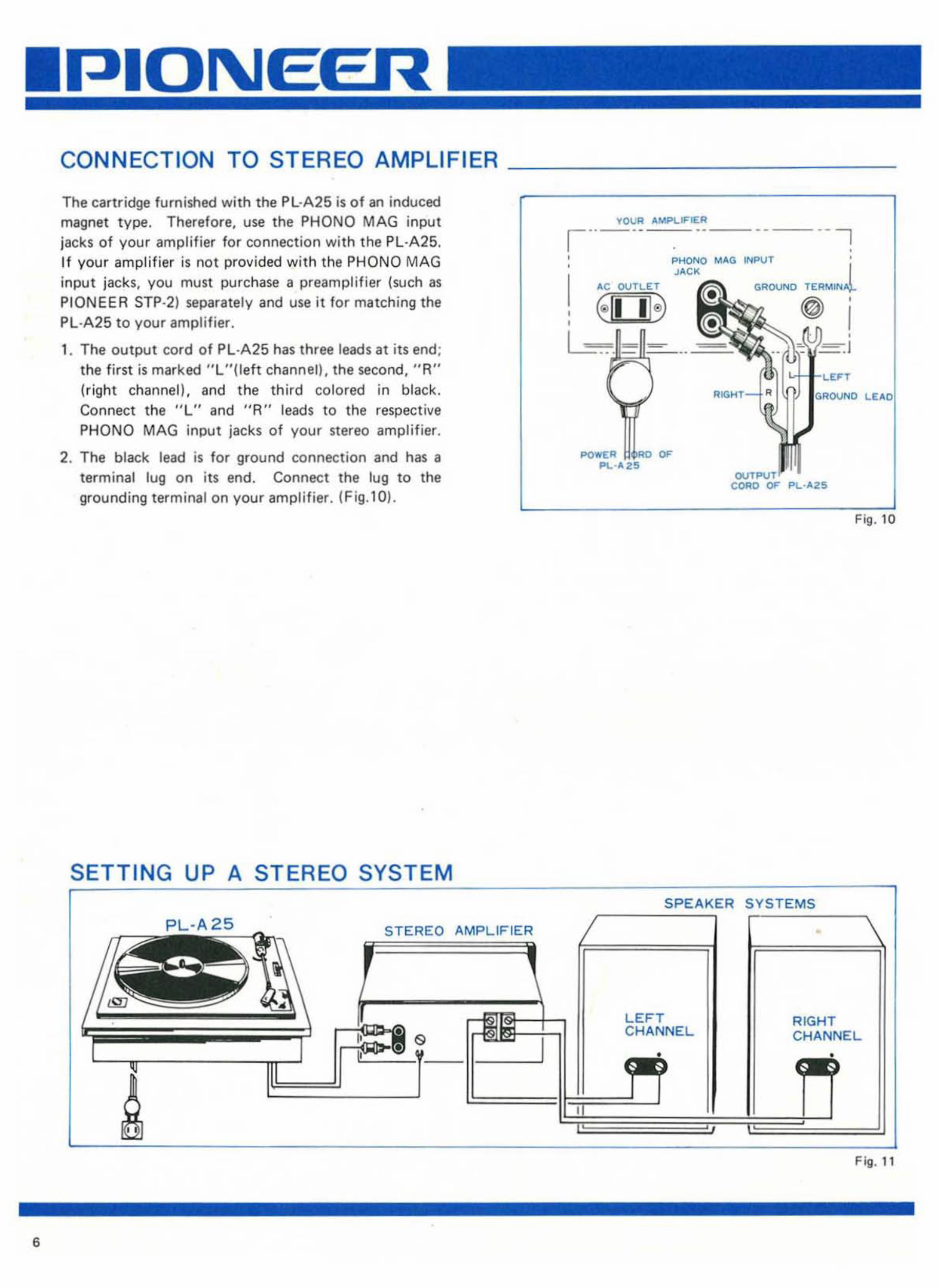
CONNECTION TO STEREO AMPLIFIER
The cartridge furnished with the PL ·A25 is of an induced
magnet type . Therefore, use the PHONQ MAG input
jacks of your amplifier for connection with the PL·A25.
If you r ampli f ier is not provided with the PHONO MAG
input jacks, you must purchase a preamplifier (such as
PIONEER STP·2) separately and use it f or matching the
Pl ·A25 to your amplifier.
1. The output co rd of PL - A25 has three leads at its end ;
the first is marked " L "(l eft channelL the second, " A"
(ri ght channell. and the third colored in black.
Connect the "L" and "R" leads to the respective
PHONO MAG input jac ks of your stereo amplifier.
2. The black lead is for ground conn ec tion and has a
terminal lug on its end. Connect the tug to the
grounding terminal on your amplifier. (Fig. l0 ).
SETTING UP A STEREO SYSTEM
PL-
A2
c.-
5
_
STEREO AMPLIFIER
I
TOOR "MPLIFIER
1'-'-' --
-_. --'
,
,
i'>HONO M"G INF>UT l
J"CK
"C OOTLET GROUND TERMIN
€ II I@ I
,
,"ou", LE"O
Fig. 10
r-__ SYSTEMS
LEFT
CHANNEL
RIGHT
CHANNEL
Fig. 11
7
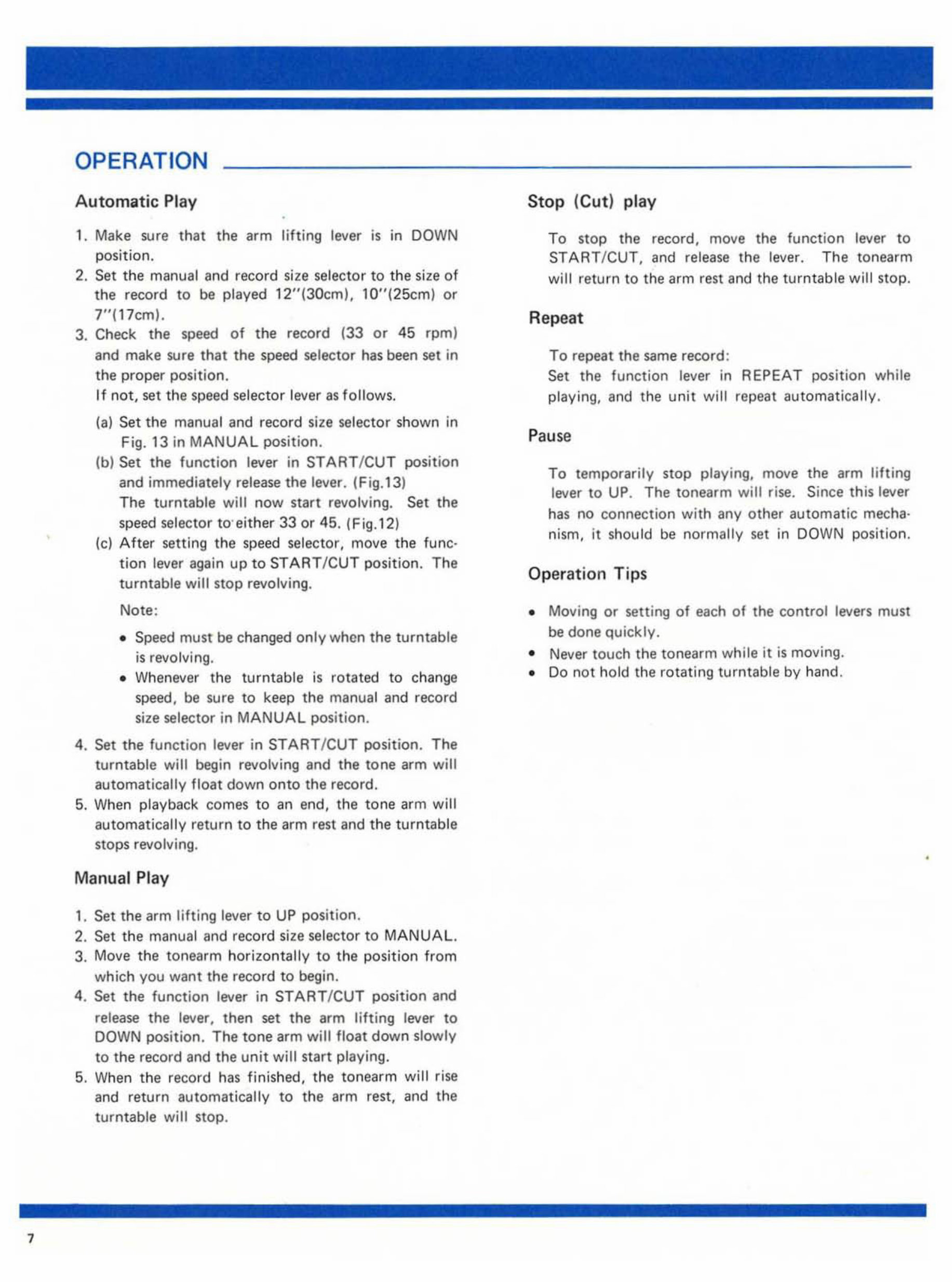
OPERATION
A ut omatic Pl ay
1. Make sure that t he arm lifting lever is in DOWN
position.
2. Set the manual a nd record size selector to the size of
the record to be played 12 "(3Otm). lO"(25cm) or
7"( 17 cml.
3. Check the speed of the record (33 or 45 rpm)
and make sure that the speed selector has been set in
the proper position.
If not, set the speed selector lever as follows.
(a) Set the manual and record size selector shown in
Fig. 13 in MANUAL position.
(bl Set the function lever in STAR T/ CUT posi t ion
and immediately release the lever. (Fig.13)
The turntable will now start revolving. Set the
speed selector to'either 33 or 45. (Fig.12)
te) After se tt ing th e sp eed selec tor, move the func-
t ion lever again up to START ICUT position. Th e
t urntable will stop revolving.
Note :
• Speed must be c han ged only when the turntable
is revolvi ng.
• W he never the turntable is rot at ed to change
speed, be sure to keep the manual and r ecord
size selector in MANUAL position.
4. Set the f unction lever in START /CUT position. The
turntable will begin revolving and the tone arm will
a utomatically float down onto th e record.
5. Wh en playback comes to an end, the t one arm will
automatically re t urn to the arm re st and the turntable
stops revolving.
Manual Pla y
,. Set the arm lifting lever to UP posit ion.
2. Set the manual and record size selector to MANUAL.
3. Move the tonearm horizo nt a ll y to the position from
which you want the record to begin.
4. Set the fun ction lev er in S TAR T/CU T position and
release th e lever, then set the arm lifting lever to
DOWN position. Th e tone arm will float down slowly
to the record and the un it will star t playing.
5. When the record has finish ed, the tonearm will r ise
and return automatically to the arm rest, and the
turntable will stop.
Stop (Cu t ) pl ay
To stop the re co r d, move the function lever to
ST ART / CUT, and release the leve r. Th e tonearm
wi ll return to the arm re st and the turnt able wi ll st op.
Rep eat
To repeat th e same record :
Set the function lever in REPEAT pos it ion while
playing, and the unit will repeat aut omatically.
P ause
To temporaril y stop playing, move the arm lifting
lever to UP. The ton ea rm will rise. Since th is lever
has no connec tion with any other automatic mecha·
nism, it sh ould be normally set in DOWN position.
Operat ion Tips
• Moving or setting of each of the control levers must
be done q uickly .
• Never touch the tonearm while it is moving.
• Do not ho ld the rotating turntable by hand .
•
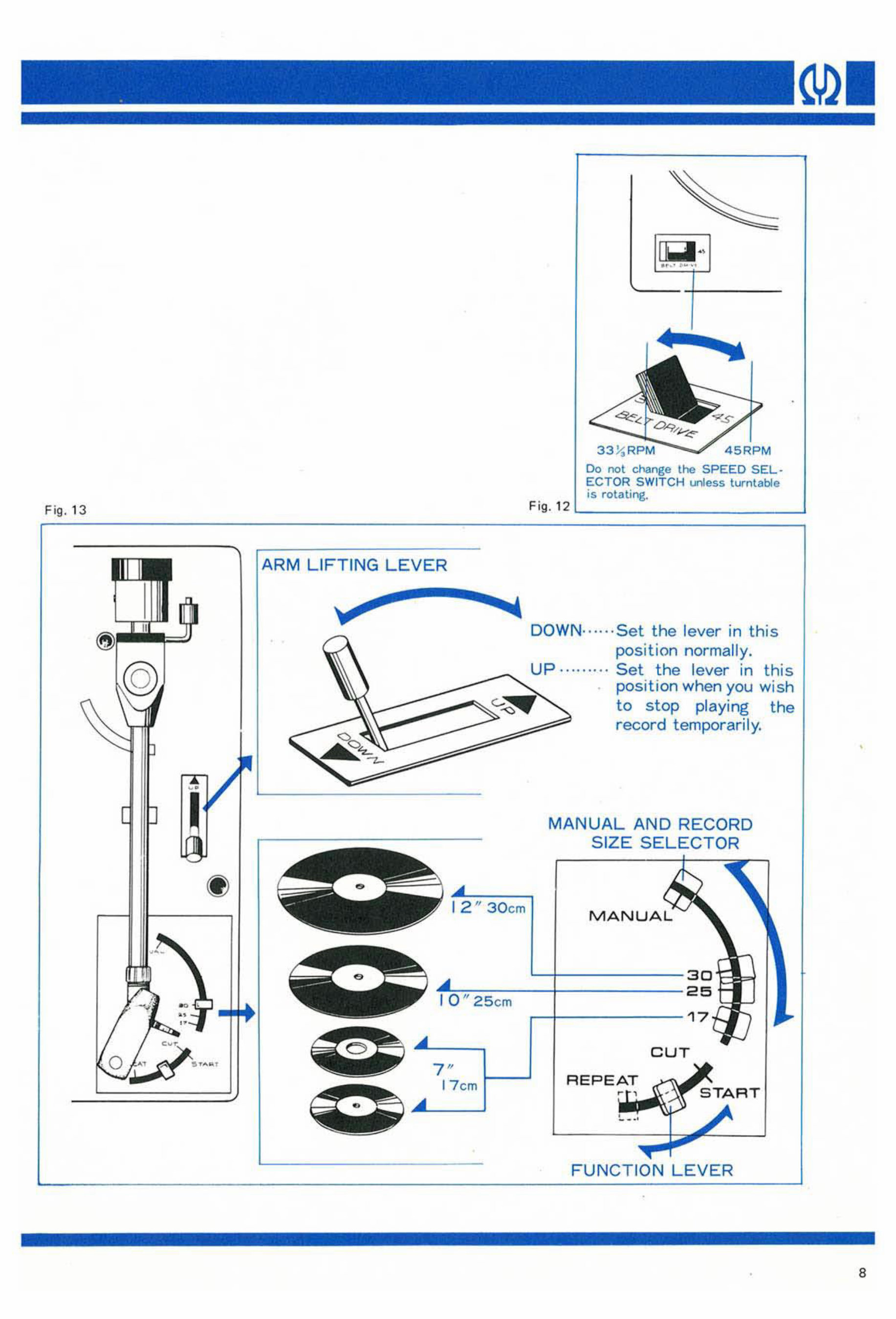
Fig. 13
o
AR M LIF T IN G LE VER
30 cm
25 cm
F ig . 12
00 not change the SPEED SEL·
ECTOR S WI TC H l.nIess turntable
is rotating.
DOWN ······ Set the lever in this
posi t ion no rma ll y.
Up · ........ Set the lever in th is
posi ti on wh en you wish
to stop playing the
record temporar il y.
MA N UA L AND RECORD
SIZE S EL ECTOR
MANUAL
CUT
7"
17 cm f- -'
REP EA T
FUNCTIO N LE VER
•
•
8
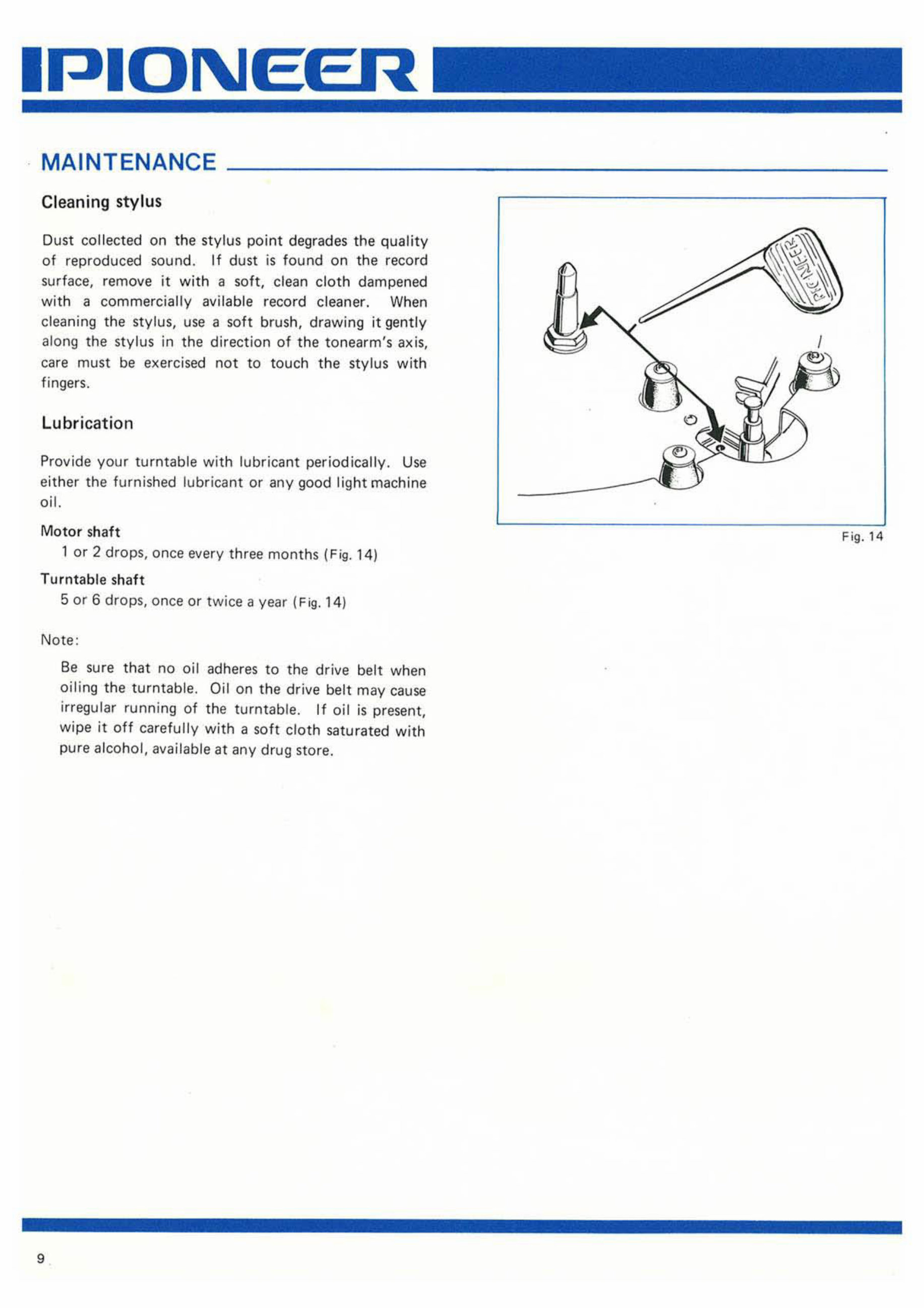
MAINTENANCE
Cleaning stylus
Dust collected on th e stylus point degrades the quality
of reproduced sound. If dust is f ound on the re cord
surface, remove it with a soft, dean clot h da mp ened
with a comme rcially avilable re cord cleaner. When
cleaning the stylus, use a soft brush, drawing it gently
along the stylus in the direction of the tonearm's axis,
care must be exercised not to touch the sty lus with
fingers.
Lubrication
Provide your turntable with lubricant periodically. Use
either the furnished lubricant or any good light machine
oi I.
Motor sh aft
lor 2 drops , once every three months (Fig. 14)
Turntable sh aft
5 or 6 drops, once or tw i ce a year ( Fig. 14)
Note :
9
Be su re that no oi l adheres to the drive belt when
oili ng the turntable. Oil on the drive belt may cause
irregular running of the turntable. If oil is present,
wipe it off carefully with a soft cloth saturated with
pure alcohol, available at any drug stor e.
Fi g. 14
You're Reading a Preview
What's Included?
Fast Download Speeds
Online & Offline Access
Access PDF Contents & Bookmarks
Full Search Facility
Print one or all pages of your manual
$27.99
Viewed 71 Times Today


Secure transaction
What's Included?
Fast Download Speeds
Online & Offline Access
Access PDF Contents & Bookmarks
Full Search Facility
Print one or all pages of your manual
$27.99
Pioneer PL-A25 High Fidelity Automatic Stereo Turntable Factory Manuals are available in PDF format. These manuals include Operating Instructions spanning 14 pages and a Service Manual spanning 11 pages. They are valuable resources for both professional mechanics and DIY enthusiasts.


