


SERVICE
MANUAL
THE MAGNAVO X COMPANY • SERVICE DEP ART MENT
FORT WAYNE. I ND IANA
• • •
5275
MODELS W602, W603, W604, W605, W606, W607 & W608
AUTOMATIC RECORD PLAYERS
. .. ·- ..... "'-"""-- ........
•
' :
Mc:agnavox
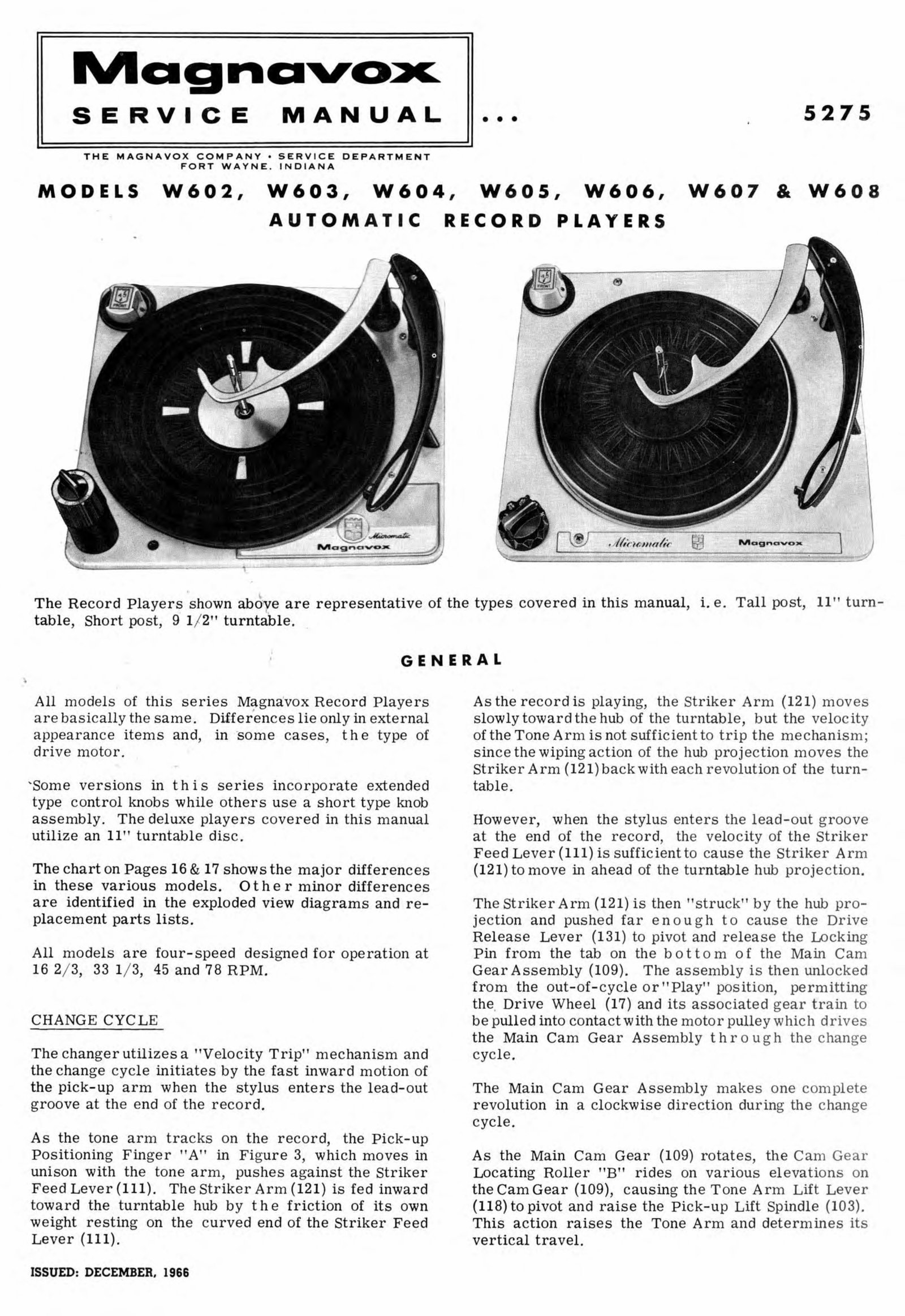
The Record Players shown abo ye are representative of the types covered in this manual, i. e. Tall post, 11" turn-
table , Short post, 9 1/ 2" turntable .
•
·'
GENERAL
All mo dels of this series Magna:vox Record Players
I
are basically the same. Differences lie only in external
appearance items and, in · some cases, the type of
drive motor .
'Some versions in this series in corpora te extended
type co ntrol knobs while ot her s use a s ho rt type knob
assembly. The deluxe players covered in this manual
utilize an 11" turntable dis c.
The chart on Pages 16 & 17 shows the major differen ces
in these various models. 0 the r minor difference s
are identified in the exploded view diagram s and re-
pl acement parts lists.
All models are four-speed designed for ope rati on at
16 2/ 3, 33 1/ 3, 45 and 78 RPM.
CHANGE CYCLE
The changer utilizes a "Velocity Trip" mechanism and
the c han ge cyc le initiates by th e fast inward motion of
the pick -up arm when the s tylus e nters the lead-out
gr oove at the end of the record.
As the tone arm tracks on the record, the Pick-up
Positioning Finger "A " in Fi gure 3, whi ch moves in
uni so n with the tone arm, p ushe s against the Str iker
Feed Lever (111). The Striker Arm (121) is fed inward
toward the turntab le hub by the friction of its own
weight resting on th e curve d end of the Striker Feed
Lever (111).
ISSUED: DECEMBER, 1966
As the r ecord is playin g, the St riker Arm (12 1) moves
slowly toward the hub of the turntable, but th e velocity
of the Tone Arm is n ot sufficient to trip the mec hanism;
since the wipin g a c ti on of the hub projection moves the
Striker Arm (121) back with each revolution of th e turn-
table.
Howe ver, when the stylus enters the lead-out groove
at the end of the record, the vel ocity of the Striker
Feed L ever (111) is suf fi cient to c au se the Striker Arm
(121) to move in ahead of the turntab le h ub projection .
The Striker Arm (121) is then "struck" by the hub pro-
jection and pushed far enough to ca u se the Drive
Release Lev er (131) to pivot and release the Locking
Pin fr om the tab on the bottom of the Main Cam
Gea r Assembly (109). The ass e mbly is then unl ocked
from the out -of-c ycle or" Pla y" posi ti on, permitting
the. Drive Wheel (17) and its a ssocia t ed gea r train to
be pulled into co nt act with the mot or pulley which drive s
the Main Cam Gear Assembl y thr ough the cha nge
cycle.
The Main Cam Gear Assembly makes one complete
revolution in a clockwise dire c ti on durin g the change
cycle .
As the Main Cam Gear (109) rotat e s, the Cam Gear
Locating Roller "B" rides on variou s el evations on
the Cam Gear (109), causin g th e Tone Arm Lift Lever
(118) to pivot and rai se the Pi ck -u p Lift Spindle (103).
This action raises the Tone Arm and deter mines its
vertical travel.
5275·2
ON-O t FF
SW
1
ITCH
ASSEMBLY
IDLER WHEEL
HI EI I GHT ADJ.
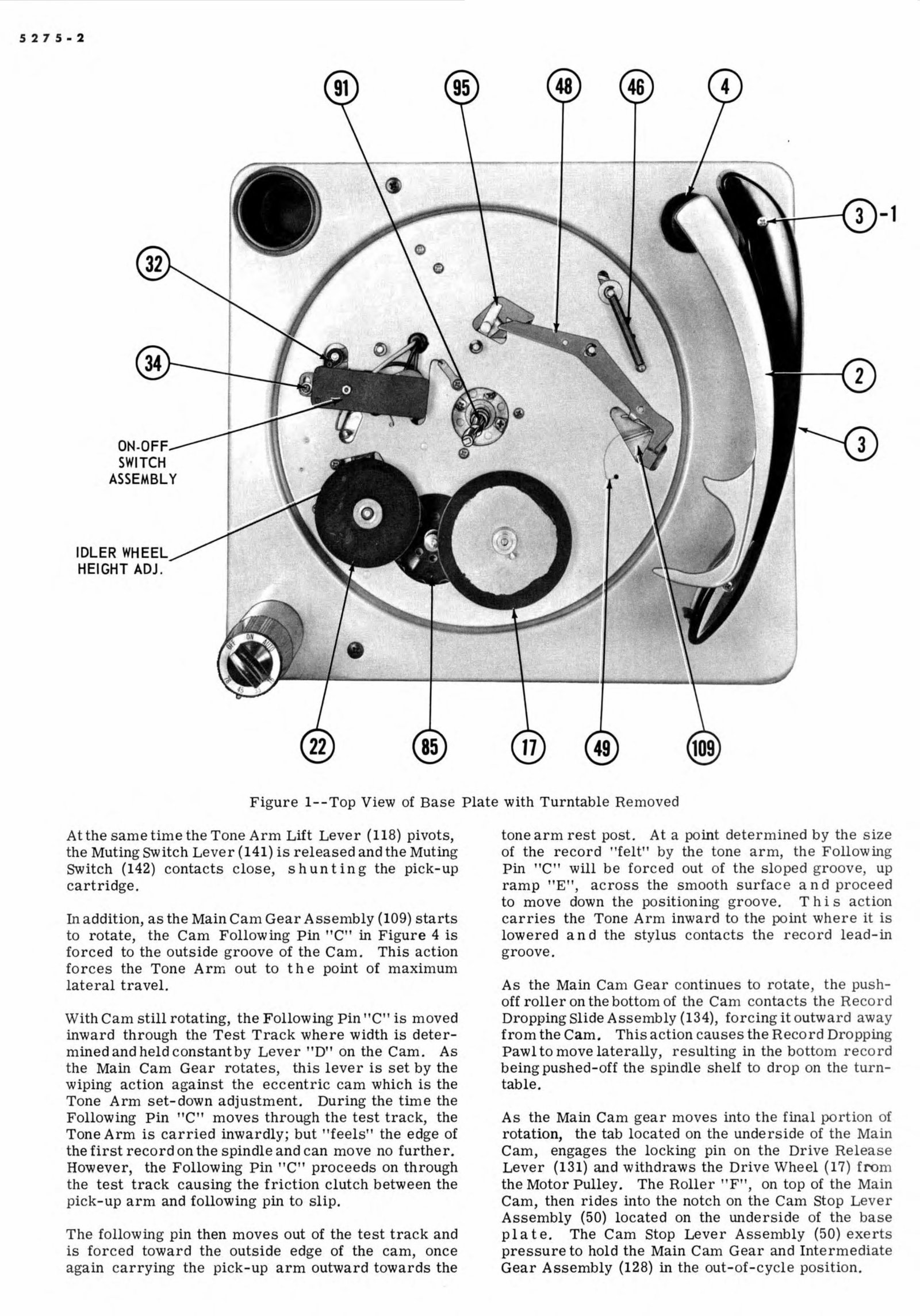
Figure 1--Top View of Base Plate with Turntable Removed
At the sa1n ·e time the Tone Arm Lift Lever (118) pivots,
the Muting sw· itch Lever {141) is released and the Muting
Switch (142) contacts close shunting the p1ek-up
ca . rtri dge.
In addition, as the Main Cam Gear Assen1bly (109) starts
to rotate, the Cam Following Pm "C" in Figure 4 is
forced to the outside groove of the Cam. This action
forces the Tone Arm out to the point of . maximum
lateral traveL
With Cam still rotating, the Following Pin ''C
1
' is moved
inward through the Test Track where width is deter-
mined and held constant by Lever ' '.D" on the Cam.. As
the Main Cam Gear rotates, this lever is set by the
wiping action against the eccentric cam which is the
·Tone Arm set-down adjustment.. During the time the
Following Pin "C"' moves through the test track, the
Tone A. rm is carried inwa . rdly; but "fee ls ' the edge of
the first r· ecord on the sp1ndle and can move no further.
Howev· er, the Following Pin "C ' proceeds on through
the test track causing the friction clutch between the
pick-up arm and following pin. to sli.p.
The · following pin then mov. es out of the test track and
is forced toward the outside edge of the cam, once
again carrying · the pick-up arm outward towards the
tone arm. r · est post. At a point detert nine d by the size
of the record ·'felt
1
' by the tone arrn, the Following
Pin uc ·n will be forced out of the sloped groove up
ramp ''E' ·, across the smooth surface and proceed
to move down the positioning groove. This aetion
carries the Tone Arm inward to the point wher ·e it is
lowered and the stylus contacts the record l· ead-in
groove.
As the Main Cam · Gear continues to rotate the push-
off roller on the bottom of the Cam eontaets the Reco 1 d
Dropping Slide Assembly (134), forcing it outward away
from the Ca.m., This action cause .s the Record Droppin.g
Pawl to move laterally, resulting in the bott om record
being pushed-off the spindle shelf to drop on the turn-
table.
. As the Main Cam gear moves into the final portion of
rotation, the tab located on the underside of the Main
Cam, engages the locking pin on the Drive Release
L· ever (131) and withdraws the Drive Wheel (17) from
the Motor Pulley. The Roller 'F ·, on top of the Main
Cam, . then rides into the notch on the Cam Stop Lever
Assembly (50) located on the underside of the base
plate. The Cam Stop . Lever Assembly (50) exerts
pressure to hold the Main Cam Gear and
Gear Assembly {128) in the out-of-cycle posit1on.
(MOLEX)
COHN' ECTOR
•
0
Q
MUT I ING
.SWITCH
5275 3
-·
A
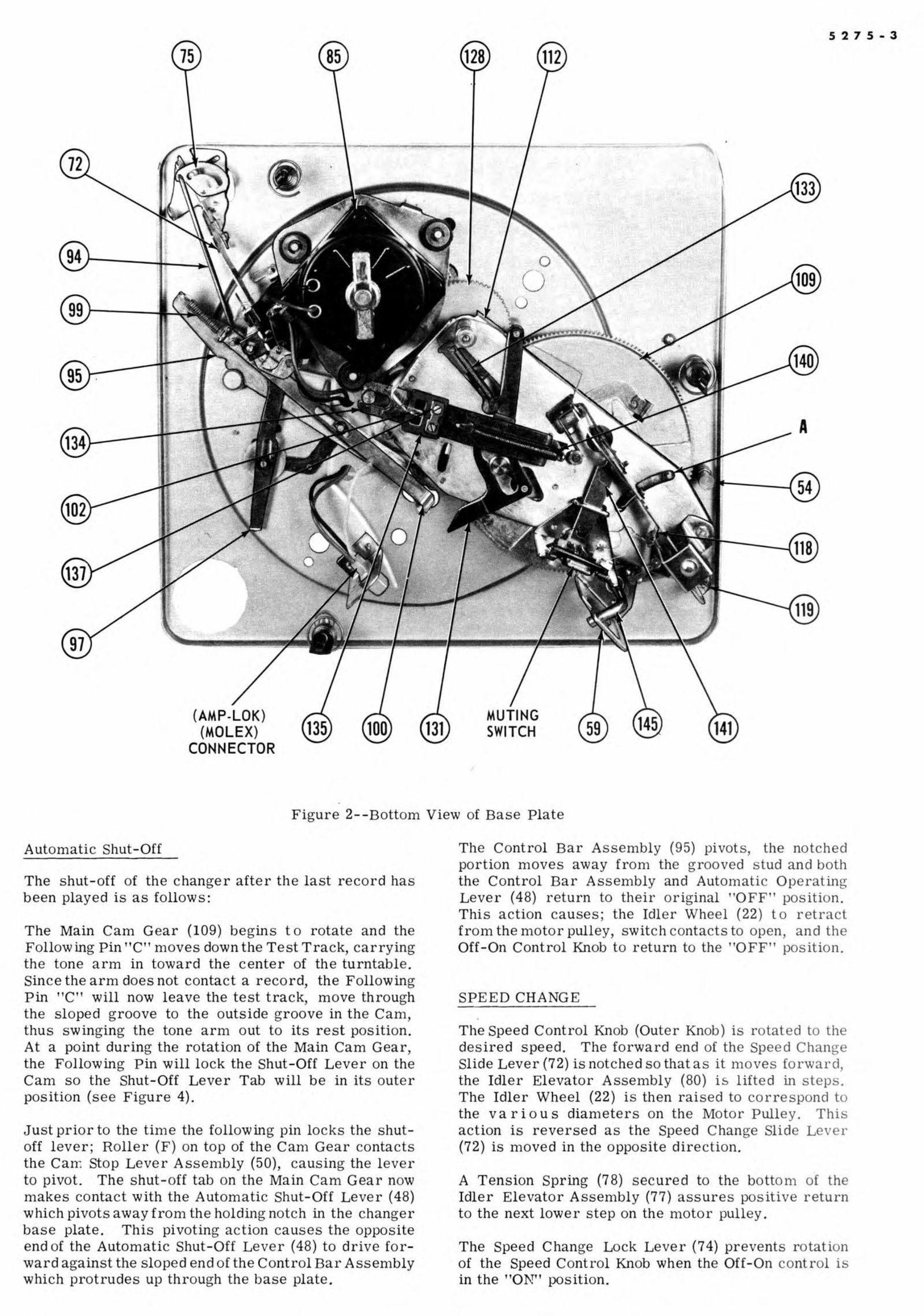
Figure 2--Bottotn View of Base Plate
Automatic Shut-Off
The shut-off of the changer after the last record has
been played is as follows:
The Main Cam Gear (109) begins to 1otate and the
Following Pin'' C
1
' moves down. the Test Track , carrying
the tone arm in toward the center of the turntabl ·e.
Since the arm does not contact a record, the Following
Pin · 'C'' will now leave the test track, move through
the sloped groove to the outside groove in the Ca .m .
thus swinging the tone ar1n out to its rest position.
At a point during the rotation of the Main Cam Gear
the Following Pin will lock the Shut-Off Lever on the
Ca.m so the Shut-Off Lever Tab will be in its outer
position (see Figure 4).
Just prior to the tin 1e the following pin locks the shut-
off lever· Roller (F) on top of the Can1 Gear contae s
the Stop Lever Ass e1nbly (50), causing the lever
to pivot. The shut-off tab on the Main Cam Gear no\v
makes contaet w" th the Automatic Shut-Off Lever (48)
which pivots away from the holding notch in the changer
base plate. This pivoting action c auses the opposite
end of the Automatie Shut-Off Lever (48) to drive for-
ward against the slope ·d end of the Control Bar Asse1nbly
which protrudes up through the base plate.
Th . Control Bar A ssembly ('95·) pivots the notched
por tio n move away fro1n the grooved tud and both
the Control Bar Assen1bly and Aut omati ,-· Opera tin
Lever ( 48) return to their or ig inal · position.
This a. ction caus s · the Idler W' heel (22) to retract
fro1n the tnotor pulley, switch contacts to open and th
Off- ·On Control Knob to return to the · 'OFF' position.
SPEED CHANGE
.
The Spe · ed Control Knob (Outer Knob) i rotated to th
desired speed. The forward end of the Speed Ch nge
Slide Lever (72) is notched so that as it n1ove forw rd
the Idler Ele· vator Assembl y (80) i lifted in step .
The Idler Wheel (22) is then rai sed to correspond t
the v a rio us diamete1 s on Motor Pulley. Thi
aetion is reversed as the Speed Change lid L v r
(72.) is moved in the opposite direc tio n.
A Tension Spring (78) to the bot on1 f h
Idler Elevator Assen1bly {77) as ures positiv return
to the next lower step on the motor pulley.
The Speed Change Lock Lever (74) prev e nt s rotati on
of the Speed Control Knob when the · Off-On control i
in the 'ON position.
5275.-4
Remote Record Rej eet Operation
On some units a Record Reject solenoid is mounted on
the changer sub-plate (see Figure 9' ).. An extension
of the solenoid piston protrudes through an opening in
OPERATING
1. Lift Balance Arm and swing it out over the Tone
Arm.
2. Place a quantity of records , not ten , on
the record spindle and lowe.r them to th·e spindle
off-set step. T'o insure proper indexing, records
of different siz· es must be stacked w itb the largest
size at the bottom. Be certain all recor· ds are of
the same speed.
3. Place Balance Arm over the records and
the correct stylus ..
4. Set Speed Control Knob (Outer Knob) to correct
speed ..
NOTE: This control cannot be rotated when the
On-Off control is in the '·ON" position.
5. Rotate the On-Off Control (Inner Knob) to its maxi-
m.um. clockwise position and release it when the
turntable starts to revel ve. The Tone Arm will
now move over and set down on the· first record.
To reject rotate this control clockwise to the
'AUTO" position and release tt.
Adapter for 45 RPM Records
1. Be sure the On-Off Control Knob is in the · 'OFF"
position. Place adapter over spindle with the
the sub-plate and pushes against the striker arm on the
velocity trip n1echanism . The arn1 is then pushed
back by the hub projection and unlocks the main cam
gear to start the change cycle.
INSTR . UCJIO . NS
arrow on top of spindle pointing towards the front
of changer.
2. Press downward on ad apt e r until it is firmly
seated. The arrow will be pointing to the left of
center when the adapter is in place.
3. To remove the adapter, pull it straight up from the
spindle.
Manual Play
l. Lift the Record Balancing Arm and swing it out
over the T'one Arm.
2. Place the record on turntable spindle.
3... Set the Turntable Speed Control ('Outer Knob) to
correspond to the type of record being played.
Select the correct stylus.
4. Rotate the On-Off clockwise to the ' ON ' pos it ion.
5. Manually place the stylus gently on the
After the record has been played, the tone ar1n
will return to its rest position and the instrume nt
w i 11 shut-off automatically. If only a sel ec ted
passage is to be played, the tone arm can be lifte d
and placed on its rest manually afteT the passa ge is
completed.
ST iR I KE IR ARM
STRIKER FEED
LEVER
'
1
1
1 1
1.2
;;-: .. .
FR iCT: ION CLUTCH
ASSEMBLY - 76130266
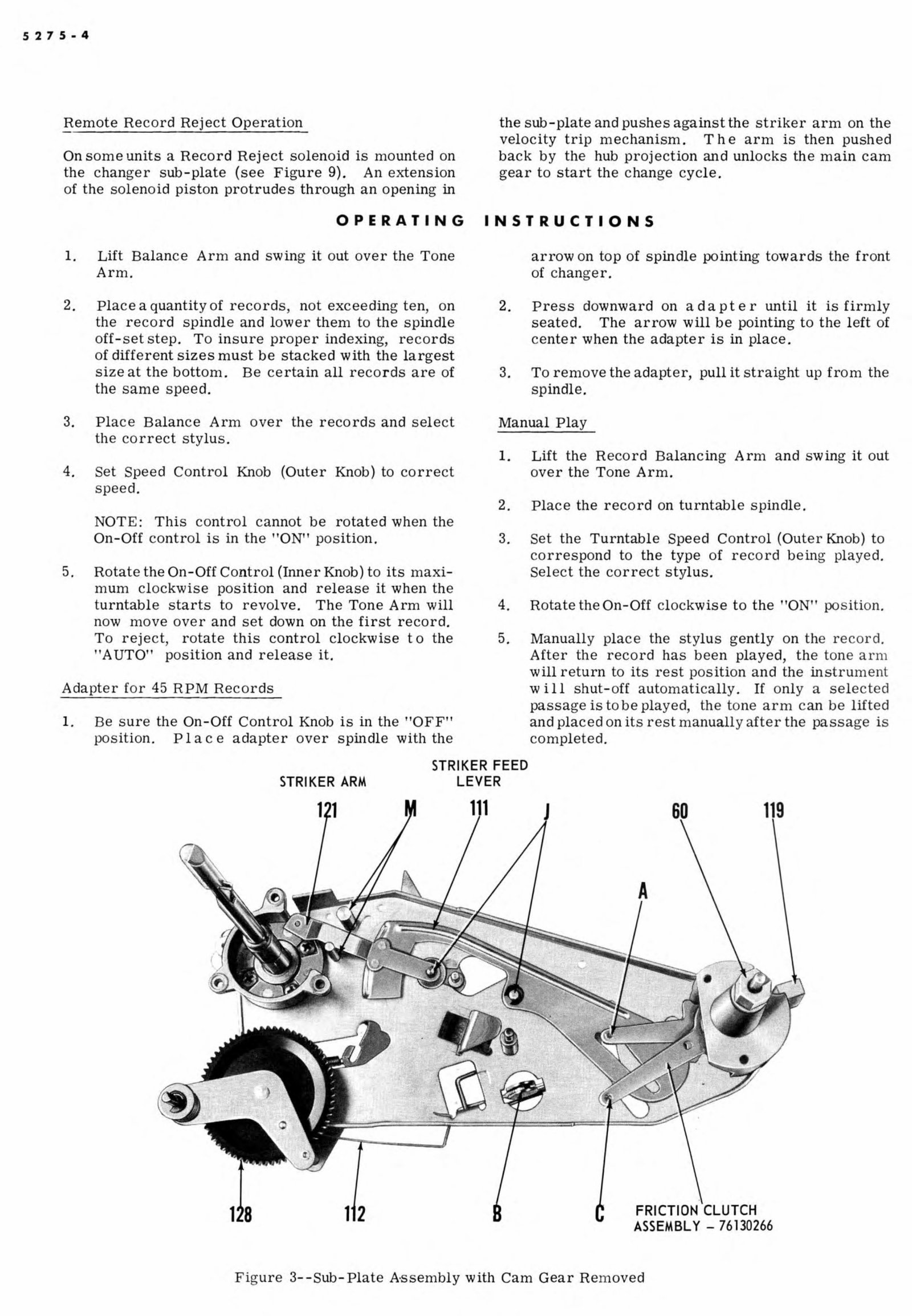
Figure 3--Sub-Plate A·ssembly with Cam Gear Re t noved
ADJU ST M, ENT S
Tone Arm Set-Down
All changers in this series provide automatic posi-
tioning for the various sizes of records by ''sampling'
the outside of the botto1n record resting on the
spindle The stylus then eontacts the record,
after it has fallen to the· turntable, approximately
1/ 16" from the outer edge, or on a diameter 1/ Bn
smaller than the original sampling made by the tone
arm.
This adjustment has been accurately set at the factory
however, should adjustn1ent be required in the field
a screwdriver adjustment 'G (Figure 5) i.s provided
in the base plate just forward of the tone arn1 pivot.
This adjustment consists of an eccentric cam which
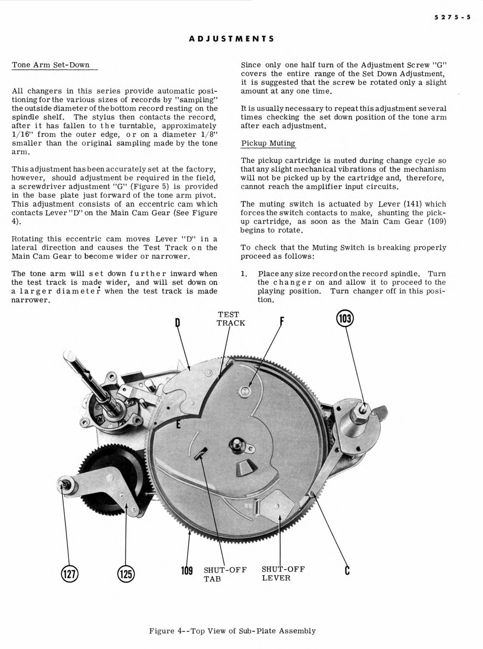
contacts Lever .. ,D 'on the Main Cam Gear (See Figure
4).
Rotating this eccentric cam. moves Lev· er
1
D · in a
lateral direction and causes the Test Track on the
Main Cam Gear to becom.e wider or narrower.
The tone arm will s e t down f u r t h e r inward when
the test track is n1ade wider, and will set down on
. . . .
a larger diameter when the test track is made
narrower.
Since only one half turn of the Adjustment Screw "G''
the entire range of the Set Down Adjustment,
it is suggested that the screw be rotated only a slight
an1ount at .any one time.
It 1s usually necessary to repeat this adjustment several
times checking the set down position of the tone arm
afte .r each adjustment.
Pickup Muting
The pickup cartridge is . muted during ehange cycle so
that any slight mechanical vibrations of the mechanism
will not be picked up by the cartridge and, therefor ·e,
cannot reach the amplifier input circuits.
The m. uting switch is actuated by Lever (141) which
forces the switch contacts to make, shunting the pick-
up cartridge, as soon as the Main Ca1n (109)
begins to rotate.
To check that the Muting Switch is breaking properly
proce · ed as follows: ·
1. Place any size record on the record spindle.. Turn
the c hang e r on and allow it to proceed to the
playing position. Turn chang· er off in this posi-
tion.
TEST
TRACK
SHUT-OFF
T. AB
-OFF
LEVER
Figure 4--Top View of Sub-Plate Assembly
5275-6
2. Check the gap between the :rnuting switch contacts
to be certain that a strip of newspaper or a metal
l feeler" gauge. 003' thick can be inserted between
tben1 (this is rniniinutn. gap}.
3. If there is no gap, or if the gap 'is insufficient,
the tag end of the Switch Operating Lever (141)
may be slightly bent away from the sub-plate
assembly.
Pickup Tracking Adjustments
Improper pickup tracking may be caused by any one of
the following:
1. Insufficient slack in pickup leads.
Check to be sure that the pickup leads are free
and that sufficient slack is maintained
the rear of tone arm and baseplate.
2. Cam Following Pin 'C ., touching bottom of cam
groove.
Check to see if the Cam Following Pin 'C" is
rubbing bottom of cam groove when in the ''playing
recess"'. This pin i.s properly positioned when it
touches halfway up ramp Figure 4}.
This adjustment is made by rotating screw "I"
(Figure 7).
3. Striker Feed Lever (Ill) resting on sub-plate.
Check to see that the Striker Feed Lever (Figure
3,) is perfectly free on its pivot ' J' and is con-
tacting the sub-plate at its forward end (under the
Striker Arn1). At the time the Striker Feed
Lever clear of the sub ·- plate at the rear
end by approximately 1/ 1, 6''. If this clearance is
insuffi . cient, it may be increased by inserting a
screwdriver between the Striker Feed Lever (111)
and sub-plate and exerting a slight upward pres-
sure.
4. Chipped or damaged stylus.
If it is suspected the pickup stylus is worn or
damaged replacement is to be made with an exact
stylus of the original type {see Pick-
up and stylii information on Page I 1).
Insufficient stylus pressure ..
See , Stylus Pressure Adjustment'.
Tone Arm H· eight
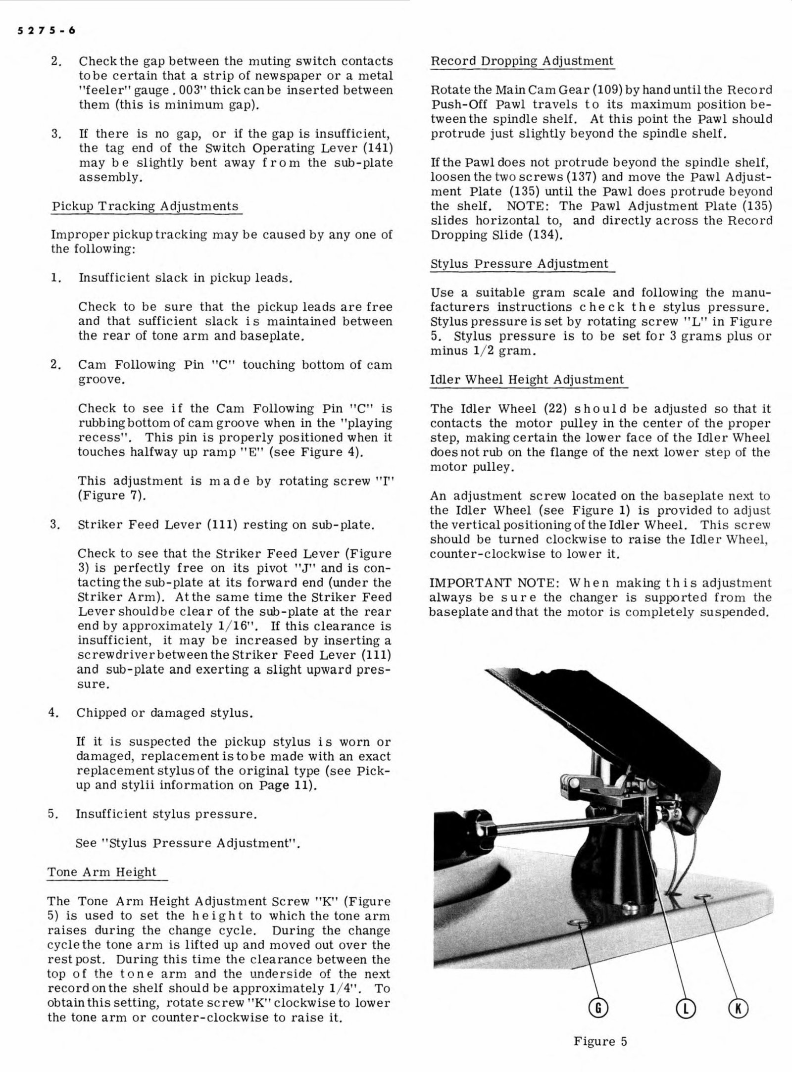
The Tone Arm Height Adjustment Screw 'K" (Figure
5) is used to set the height to which the tone arn1.
raises during the change cycle. During the
cycle the tone arm is lifted up and moved out over the
rest post. During this time the clearance between the
top o f the t on e arm and the underside of the next
record on the shelf should be approxilnately 1/ 4''. To
obtain this setting, rotate screw' K'r elockwise to lower
the tone arm or counter-clockwise to raise it.
Record Dropping Adjustment
the Main Cam Gear (I OB) by hand until the Record
Pawl travels to its maximun1 position be-
tween the spindle shelf. At this point the Pawl should
protrude just slightly beyond the spindle shelf.
If the Pawl does not protrude beyond the spindle shelf
loosen the two screws (137) and n1ove the Pawl Adjust-
ment Plate (1 ,35) until the Pawl does protrude beyond
the shelf. NOT' E: The Pawl Adjustment Plate (135)
slides horizontal to,, and directly across the Reeord
Dropping Slide { 134) ..
Stylus Pressure . Adjustment
Use a suitable gram scale and following the lnanu-
facturers instructions c he c k t h e stylus pressure.
Stylus pressure is set by rotating screw ''L -
1
in Figure
5. Stylus pressure is to be set for 3 grams plus or
minus 1/ 2 gram.
Idler Wheel Adjustment
The Idler Wheel {22) should be adjusted so that it
contacts the motor pulley in the center of the proper
making eertain the lower face of the Idler Wheel
does not rub on the flange of the next lower step of the
motor pulley.
A.n adjustment located on the baseplate next to
the Idler Wheel (see Figure l) is provided to adjust
the vertical positioning of the Idler Wheel. This screw
should be turned clockwise to raise the Idler Wheel
counter-clockwise to lower it.
IMPO , RTANT NOTE: When making this adjustn1ent
always be sure the changer is supported from the
baseplate and that the motor is completely suspended ..
Figure 5
AC Switch Adjustment .
Remove Turntable as outlined under "Turntable Re-
m. oval". Rotate the On-Off Control Knob to the 'ON'
position.
Loos · en SWitch Adjustn1ent S c r e w (34) and remove
SWitch Cover (29) by removing Nut (31) and Washer
(.30).
Slowly rotate switch body c lockwise until the contact
strip (farthest from the actuator) is move d approxi-
mately 1/ 64' · from its rest. Tighten Switch Adjustment
Screw {34) while holding the switch in this position.
Replace Switch Cover, Washer and NuL
Automatic Trip
Failure of the 1nechanism to trip at the end of a re-
cord may be due to any one of the· follow'ing:
527 . 5-7
1. Tightness or dirt on Pivots ' J,, see Figure 3.
Remove C-clips from Pivots "J" and ren10V'8
Striker Feed L· ever and Striker Arn1. Clean
Levers and Pivots and replace. Re-fit C- clips
and cheek to be sure the Levers will travel their
full excursion when the sub-plate is tilted in a
45 degree angle.
2. Striker Feed Lever (111) re· sting on sub-plate at
reai' end.
a ..
Insert a small screwdriv, er between the sub-plate
and Striker Feed Lever (111) and exert a slight
upward pressure. The Striker Feed Lever should
he perfectly free on its pivot contacting the base-
plate at its forward · end only.
Dirt on Pins labeled 'M", Figure 3.
Clean Pins !fM' · to be sure they are e on1pletely
free of any dirt and grease of any kind.
INSTRUCTIONS FOR SERVICING AND REPLACEMENT
OF PAR S
Turntable Removal
1.. Place the On-Off control knob in the 'OFF" posi-
tion and remove the E-Clip (9) from center of
turntable.
2. Remove turntable by grasping outside ·edge and
lifting straight upward with a slight back and forth
rotary motion ..
3. Check that the Ball Thrust Cage {14) and Washers
are free from foreign matter and lubricated with
a small quantity of light grease. The Ball Race
Cage is to be replaced with the open side facing
downward. There should be a stee l thrust washer
(15) immediately below and immediately above
the Ball Race Cage {14). (See Exploded View in
Figure 14). A. Resilient Washer (12) isfitted
bet ·w.e · en the upper-most ste , el washer and the
turntable hub and self-aligning 'di.mpled' washer
is located below the bottom Thrust Washer.
4.. Make certain that the Idler Wheel {22) and Drive
'
Wheel (17) are in their retracted positions and will
cl ear the turntable rim when it is replaced.
5. Replace Turntable and secure E-Clip.
NOTE :: B· esides securing the turntable, the E-
Clip also retains the Record Spindle to the Spigot
Housing. The Spigot Housing (93) and spindle are
notched so as to accept the center protrusion from
the E -Clip. Be sure the E-Clip seats properly
otherwise the . Record Spindle Assembly will be-
come loose.
Idler Wheel Removal and Replacement
1.. Remove Idler Whe · el Mounting Screw ('24) and
Fiber w· asher (23).
2. LiftldlerWheel (22) straight up from its spindle.
3. R, eplace Idler Wheel by reversing the procedure
just described, being certain that all fiber washers
under the Idler Wheel are replaced exactly as
they wer ·e found ..
4. Check that the Idler Wheel rotates freely.
5. Make sure that the Idler Wheel contacts the· M otor
Pulley correct 1 y and adjust as outlined under
"Idler W' heel Height Adjustment '.
Motor Removal and Replacen1ent
1. Remove Turntable as outlined Wlder tTurntable
· Removal'.
2. Rernove· Switch Cover (29) by removing MoW1tin g
Nut (31) and Shakeproof Washer {30).
3. Rem. ove ground lead and unsol der the black wire
from the foremost switch contact.
4. Clip the red wire which conn ects to the AC socket
(this lead can b·e spliced when the motor is re-
5. Remove the 3 motor mount ing C- clips and washer s.
6. The motor can now be l: ifted from the moW1ting
studs complete with grommets (84) and mounting
plate.
7.. 'R· everse the foregoing procedure to rea semble.
If the switch contacts have been ren1oved be ur ,
they are positioned cor.r ectly before replacing
switch cov , er. (See "AC Switch Adju tn1ent' ).
AC Switch Replacement
1. Remove Nut (31) and Washer (30) and lift f
Cover (29).
2. Lift out Contact Separator (25) and swit h contact
(26).
3. . Remove Adjustment Screw (34) and remove . w'itch
housing motmtin g screw from under ba. eplate.
4. Reverse the foregoing procedure to rea semble.
5275-8
Idler Swivel Arm Removal and Replacement
1. Remove Turntable as outlined under "Turntable
Removal".
2. Remove Idler Wheel as out lined under "Idler
Wheel Removal and Replacement".
3. Set Speed Control to "16" and turn the On-Off
Control Knob to the "ON" position .
4. Remove C-clip (67) from the top of the Swivel
Arm (68) and lift Swivel Arm from spindle .
5. Reverse the fore going procedure for replacement
of new Swivel Arm .
NOTE: After in stalling new Swivel Arm, re-adjust
Idler Wheel height as o utlined under "Idler Wheel
Height Adjustment" .
Control Knob Removal (Extended Type)
1. Re move On-Off Control Knob (36), C-Clip (37),
and Washer (38).
2. Remove inverted hex-nut in well of Control Indi-
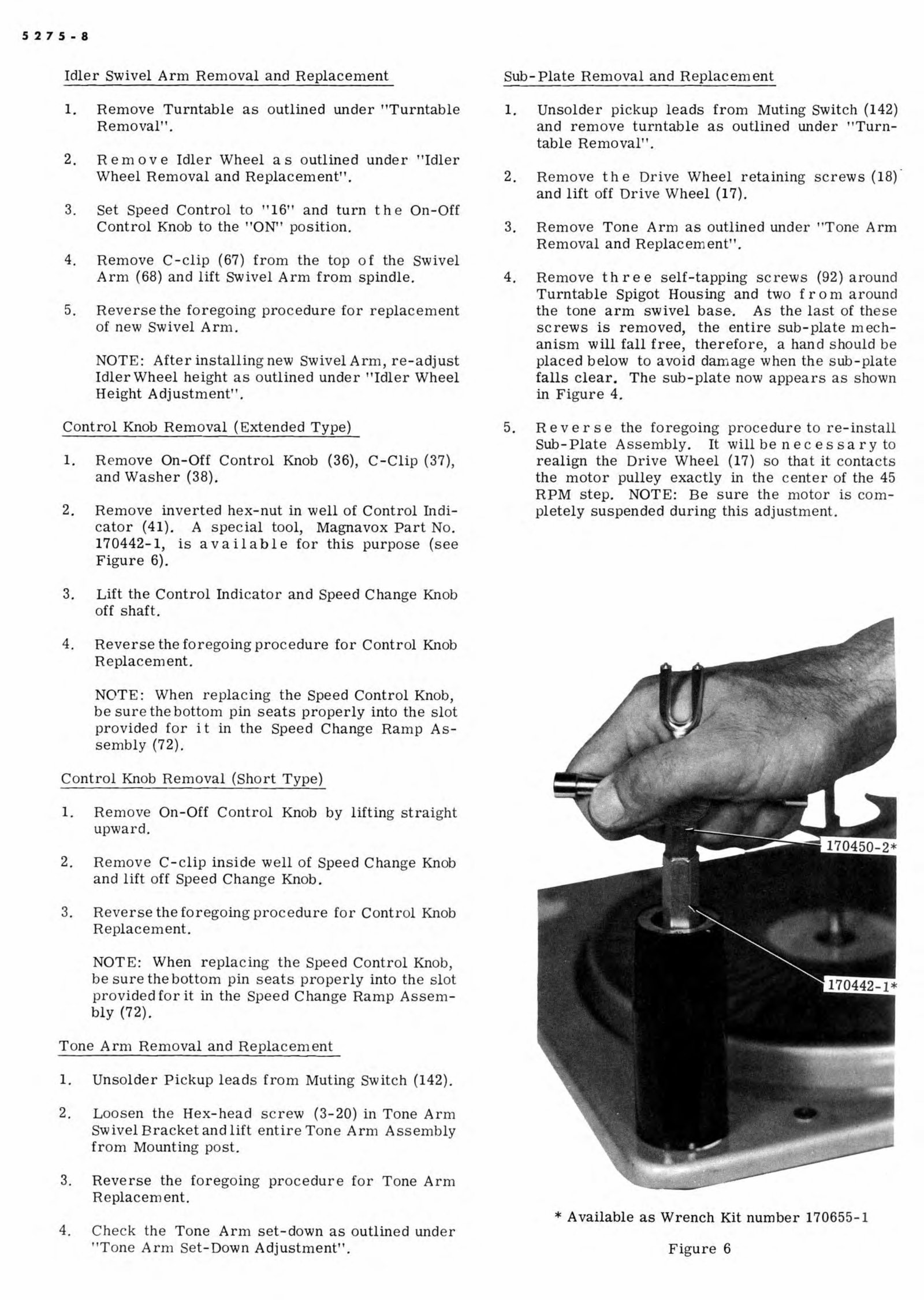
cator (41). A special tool, Magnavox Part No.
170442-1, is available for this purpose (see
Figure 6).
3. Lift the Control Indi cator and Speed Change Knob
off shaft.
4. Reverse the for egoing procedure for Control Knob
Replacement.
NOTE: When repla c ing the Speed Control Knob,
be sure the bottom pin seats properly int o the slot
provided for it in the Speed Change Ramp As-
sembly (72).
Control Knob Removal (Short Type)
1. Remove On-Off Co ntr ol Knob by lifting straight
upward .
2. R emove C-clip inside well of Speed Change Kn ob
and lift off Speed Chan ge Knob.
3. Reverse the foregoing procedure for Contr ol Knob
Replacement.
NOTE: When repla ci ng the Speed Control Knob,
be sure the bottom pin sea ts properly into the slot
provided for it in the Speed Change Ramp Assem-
bly (72).
Tone Arm Removal and Repla ceme nt
1. Unsolder Pickup leads from Mutin g Switch (142).
2. Loosen the Hex-head screw (3-20) in Tone Arm
Swivel Bracket and lift entire Tone Arm Assembly
fr om Mounting post.
3. Reverse the foregoing procedure for Tone Arm
Replacement.
4. Check the Tone Arm set-down as o utlin ed under
"To ne Arm Set - Down Adjustment".
Sub- Plate Removal and Replacement
1. Unsolder pickup leads from Muting Switch (142)
and remove turntable as outlined under "Turn-
tab le Removal".
2. Remove the Drive Wheel retaining screws (18).
and lif t off Drive Whee l (17).
3. Remove Tone Arm as outlined under "Tone Arm
Removal a nd Replacement".
4. Remove three self-tapping screws (92) around
Turntable Spigot Housing and two from around
the tone arm swivel base-. As the last of th ese
screws is removed, the entire sub -plate mech-
anism will fall free, therefor e, a hand should be
pla ced below to avoid damage when the sub -plate
falls clear. The sub - plate now appears as shown
in Fi gu re 4.
5. Reverse the foregoing procedure to re-install
Sub- Plate Assembly. It will be n e cess a r y to
realign the Drive Wheel (17) so that it contacts
the motor pulley exactly in the center of the 45
RPM step . NOTE: Be sure the motor is com -
pletely suspended during this adju stment.
*Available as Wrench Kit number 170655-1
Figure 6
Main Cam Gear Re . moval and Replacement
1. Remove Sub-Plate Assembly as outlined under
'Sub-Plate Removal and Replacement".
2. Rotate the Cam Gear by hand to the out -of- cycle
position and lift the Cam Following Pin
1
C ·· clear
of Cam edge.
3. Remove C-Clip (107) and Washer (108) from Cam
Spindle. The Cam Gear may now be lifted from
the spindle.
4. Reverse the foregoing procedure to replace . Main
Cam. Gear.
Interm. ediate Gear Removal and Replacement
1. Rem. o v e Sub-Plate Assembly as outlined under
''Sub- Plate Removal and Replacement'.
2. Remove Mounting Nut (138) and Washer (139).
. 3. Remove C-Clip (132) holding gear op · erating lever.
4. The Intermediate Gear complete w it h Carrier
Bracket (125) and Drive Pinion may now be lifted
clear.
5. Reverse the foregoing procedure for replacement
of Intermediate Gear and Carrier Assembly.
.NOTE: Do not over tighten Nut (13.8) when re-
installing Intermediate Gear Assembly or Inte r-
mediate Gear Boss W ' ill bind against top of Sub-
Plate.
Tone Arm. Pivot Remova.l and Replacement
I. R e n1 o v e Sub ·- Plate Assembly as o utlined under
''Sub- Plate Removal and Replac ·e·m ent' .
2. Remove Cam Gear (109) as outlined under · Main
Cam Gear Removal and Replacement' .,
3. Remove the two self-tapping screw·s (106) on under-
side of Sub- Plate.
4.. L.ift Pivot Assembly clear of Sub- Plate.
5. R· everse the foregoing procedure to refit Tone
Arm Pivot Assembly ..
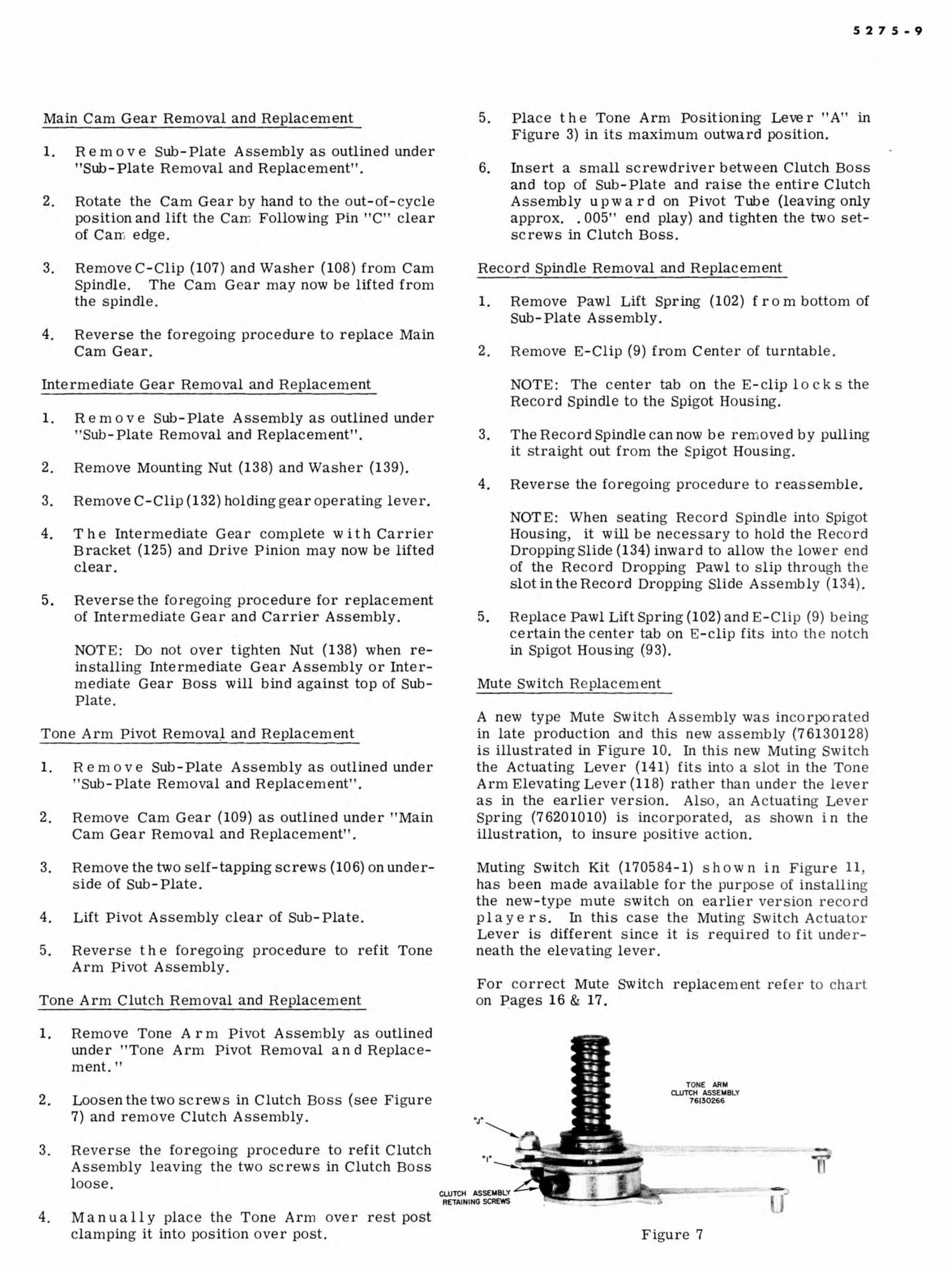
Tone Arm Clutch Removal and Replacement
1. Remove T' one Arm Pivot Assembly as outlined
under , Tone Arm Pivot Removal and Replace-
ment.''
2.. Loosen the two screws in Clutch Boss (see Figure
7) and remove Clutch Assembly ..
3. Reverse the foregoing procedure to refit Clutch
Assernbly leaving the two screws in Clutch Boss
loose.
4. Manu a.ll y place the Tone Arn1 over rest post
clatnping it into position over post.
5.. Place the Tone Arm Positioning Lever "A' in
Figure 3) in its n1aximum outward position.
6. Insert a small screwdriver betwe · en Clutch Boss
and top of Sub- Plate and raise the entire Clutch
Assembly upward on Pivot Tube (leavingonly
approx.. . 005" end play) and tighten the two set-
screws in Clutch Boss.
Record Spindle R. emoval and Replacement
I. Remove Pawl Lift Spring (102) from bottom of
Sub- Plate Assembly.
2. Remove E-Clip (9) from. Center of turntable.
NOTE: The center tab on the E- clip 1 o c k s the·
Record Spindle to the Spigot Housing.
3.. The Record Spindle can now be removed by pulling
it straight out from the Spigot Housing.
4. Reverse the foregoing procedur ,e to reassemble .
NOTE: When seating Record Spindle into Spigot
Housing . it will be necessary to hold the Record
Dropping Slide (134) inward to allow the lower end
of the Record Dropping Pawl to · lip through the
slot in the Record Dropping Slide Assembly (134).
5. Replace Pawl Lift Spring (102) and E-Clip (9) being
certain the center tab on E clip fits in to the not h
in Spigot Housing (93).
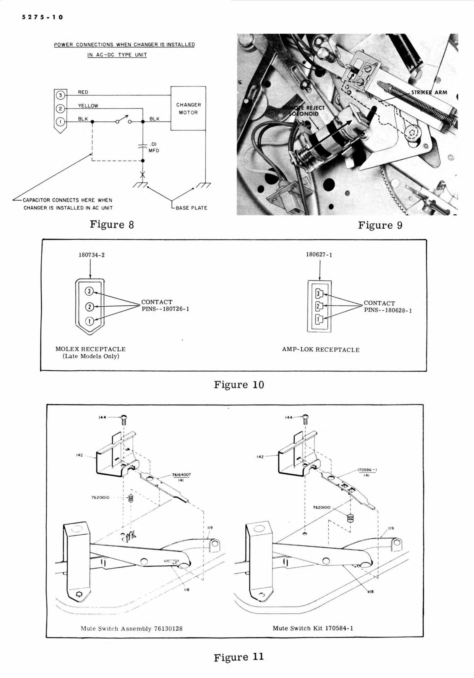
Mute Switch Replacement
A new type Mute Switch Assembly wa s incorporat d
in late production and this new assembly {76,130128)
is illustrated in . Figure 10. In this new Muting Switch
the Actuating Lever (I4I) fits into a slot in the Tone
Artn Elevating Lever (118) rather than under the lever
as in the earlier version. Also an Actuating L· ev , er
Spring (7 1010) is incorporate ·d as shown in the
illustration, to insure positive action.
Muting Switch Kit (170584-1) how n in Figure I 1.
has been made available for the purpose of i nstalling
the new-type mute switeh on earli.er version record
players. In this case th-e Muting Switch Actuator
Lever is different since it is required to fit under-
neath the elevating lever.
For correct Mute SWitch replacement refer to c ha rt
on 16 & 17.
CLUTCH ASSEMBL.Y ·
RETAINING SCREWS
TONE ARM
CUITCH ASS• EIMBLY
7il 1 30266
Figure 7
5275-10
POWER. CONNECTIONS WHEN CHANGER IS INSTAL L ED
1 N AC -OC TYPE UNIT
R'EO
YELLOW
BLK
L- ------ -
"--CAPACITOR CO·'NNECTS HERE WHEN
CHANGER IS INSTAL LED IN AC UNIT
Figure 8
180!734-2
MOLE.X RECEPTACLE
- -
(Lat Mo dels Only)
I ...
BlK
-- . 0'1
MFD
76 201010
--+ -@ '
I
--
'
,.
'
I
_.. ......
------ ..... --- --------- _,/
,
----- -- -·
CHANGER
MOTOR
.-
I I B
'wit eh As mbly 76130128
Figure 10
•
14 2
0
Figure 11
AMP-LOK RECEPTAC
, ..... ,
I
I
.... I
Mule Switch Kit 17 0584-1
Figure 9
170 586 -1
14 1
,, 9
''
I
'
'
I
You're Reading a Preview
What's Included?
 Lifetime Access
Fast Download Speeds
Online & Offline Access
Access PDF Contents & Bookmarks
Full Search Facility
Print one or all pages of your manual
$27.99
Magnavox w604,w605,w606,w607, w608 Micromatic Service Manual
Viewed 10 Times Today

What's Included?
Lifetime Access
Fast Download Speeds
Online & Offline Access
Access PDF Contents & Bookmarks
Full Search Facility
Print one or all pages of your manual
$27.99

Secure transaction
What's Included?
Lifetime Access
Fast Download Speeds
Online & Offline Access
Access PDF Contents & Bookmarks
Full Search Facility
Print one or all pages of your manual
Description
The Magnavox Micromatic Service Manual is a comprehensive guide for the maintenance and repair of the W604, W605, W606, W607, and W608 models. With 18 pages of detailed instructions, this manual provides excellent quality technical information essential for professional mechanics and DIY enthusiasts alike.


