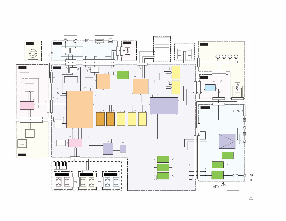
SERVICE MANUAL HAMAMATSU, JAPAN Copyright (c) Yamaha Corporation. All rights reserved. ’08.08 SY 011921 CONTENTS(目次) SPECIFICATIONS(総合仕様) .............................................. 3/4 BLOCK DIAGRAM(ブロックダイアグラム) ........................... 5 PANEL LAYOUT(パネルレイアウト) ..................................... 6 CIRCUIT BOARD LAYOUT & WIRING (ユニットレイアウト及び結線図) ......................................... 8 DISASSEMBLY PROCEDURE(分解手順) ............................. 9 LSI PIN DESCRIPTION(LSI 端子機能表) ............................. 20 IC BLOCK DIAGRAM (IC ブロック図) ................................. 24 CIRCUIT BOARDS(シート基板図) ...................................... 25 TEST PROGRAM(テストプログラム) ............................ 34/38 NG CHECK POINT BY TEST PROGRAM (テストプログラムで NG となった場合のチェックポイント) ....... 43 DATA BACKUP(ユーザーデータのバックアップ) ........... 47/51 INITIALIZATION(初期化) ...................................................... 55 SYSTEM BOOTING FLOWCHART ........................................... 56 (電源立ち上げシーケンス) .................................................. 57 DISPLAY MESSAGES(ディスプレイメッセージ) .......... 58/59 MIDI IMPLEMENTATION CHART (MIDI インプリメンテーションチャート) ......................... 60 MIDI DATA FORMAT ............................................................... 61 PARTS LIST OVERALL CIRCUIT DIAGRAM(総回路図) 20080801- オープンプライス
2 MM8 Saving and backing up your data SAVING DATA Be sure to perform it WARNING: CHEMICAL CONTENT NOTICE! The solder used in the production of this product contains LEAD. In addition, other electrical/electronic and/or plastic (Where applicable) components may also contain traces of chemicals found by the California Health and Welfare Agency (and possibly other entities) to cause cancer and/or birth defects or other reproductive harm. DO NOT PLACE SOLDER, ELECTRICAL/ELECTRONIC OR PLASTIC COMPONENTS IN YOUR MOUTH FOR ANY REASON WHAT SO EVER! Avoid prolonged, unprotected contact between solder and your skin! When soldering, do not inhale solder fumes or expose eyes to solder/flux vapor! If you come in contact with solder or components located inside the enclosure of this product, wash your hands before handling food. IMPORTANT NOTICE This manual has been provided for the use of authorized Yamaha Retailers and their service personnel. It has been assumed that basic service procedures inherent to the industry, and more specifically Yamaha Products, are already known and understood by the users, and have therefore not been restated. WARNING: Failure to follow appropriate service and safety procedures when servicing this product may result in per- sonal injury, destruction of expensive components and failure of the product to perform as specified. For these reasons, we advise all Yamaha product owners that all service required should be performed by an authorized Yamaha Retailer or the appointed service representative. IMPORTANT: This presentation or sale of this manual to any individual or firm does not constitute authorization certifi- cation, recognition of any applicable technical capabilities, or establish a principal-agent relationship of any form. The data provided is believed to be accurate and applicable to the unit(s) indicated on the cover. The research engineering, and service departments of Yamaha are continually striving to improve Yamaha products. Modifications are, therefore, inevitable and changes in specification are subject to change without notice or obligation to retrofit. Should any discrepancy appear to exist, please contact the distributor's Service Division. WARNING: Static discharges can destroy expensive components. Discharge any static electricity your body may have accumulated by grounding yourself to the ground bus in the unit (heavy gauge black wires connect to this bus.) IMPORTANT: Turn the unit OFF during disassembly and parts replacement. Recheck all work before you apply power to the unit. Components having special characteristics are marked and must be replaced with parts having specification equal to those originally installed. WARNING IMPORTANT NOTICE FOR THE UNITED KINGDOM Connecting the Plug and Cord IMPORTANT: The wires in this mains lead are coloured in accordance with the following code: BLUE : NEUTRAL BROWN : LIVE As the colours of the wires in the mains lead of this apparatus may not correspond with the coloured makings identifying the terminals in your plug proceed as follows: The wire which is coloured BLUE must be connected to the terminal which is marked with the letter N or coloured BLACK. The wire which is coloured BROWN must be connected to the terminal which is marked with the letter L or coloured RED. Making sure that neither core is connected to the earth terminal of the three pin plug. • This applies only products distributed by Yamaha-Kemble music (U.K.) Ltd. (2 wires) The panel settings and some other types of data are not retained in memory when you turn off the power to the instrument. Save data you want to keep to the Registration Memory. Saved data may be lost due to malfunction or incorrect operation. Save important data to a USB storage device/or other external device such as a computer.
3 MM8 ■ SPECIFICATIONS Keyboards MM8 88 keys (Initial touch) Tone Generator block Tone Generator AWM2 Polyphony 32 notes Multi Timbral Capacity 16 parts Wave 70MB(when converted to 16-bit linear format) Voice Preset: 418 normal voices + 22 drum kits GM: 128 normal voices + 1 drum kit Performance 8 banks x 8 Effect System Reverb x 25 types, Chorus x 30 types, Variation x 189 types Master Equalizer 5 types Sequencer block Note Resolution 96 ppq (parts per quarter note) Tempo 11–280 Recording type Real time replace Tracks 8 + 8 (Pattern track) Patterns 168 patterns (x 4 sections) Songs Preset: 3 songs User: 5 songs USB: 400 songs maximum Arpeggio Preset x 213 types Others Controllers Pitch Bend wheel x1, Modulation wheel x1, Knobs x4, Data dial x1 Display 320 x 240 dot graphic backlit LCD Connectors OUTPUT L/MONO, R (standard phone jack), PHONES (standard stereo phone jack), FOOT CONTROLLER, SUSTAIN, MIDI IN/OUT, USB (TO HOST, TO DE- VICE), DC INLET Power Consumption 12W Dimensions, Weight 1,340(W) x 445(D) x 157(H) mm, 15.6kg Accessories AC Power Adaptor, Owner’s Manual, Supplied Disk (supplied DAW software)
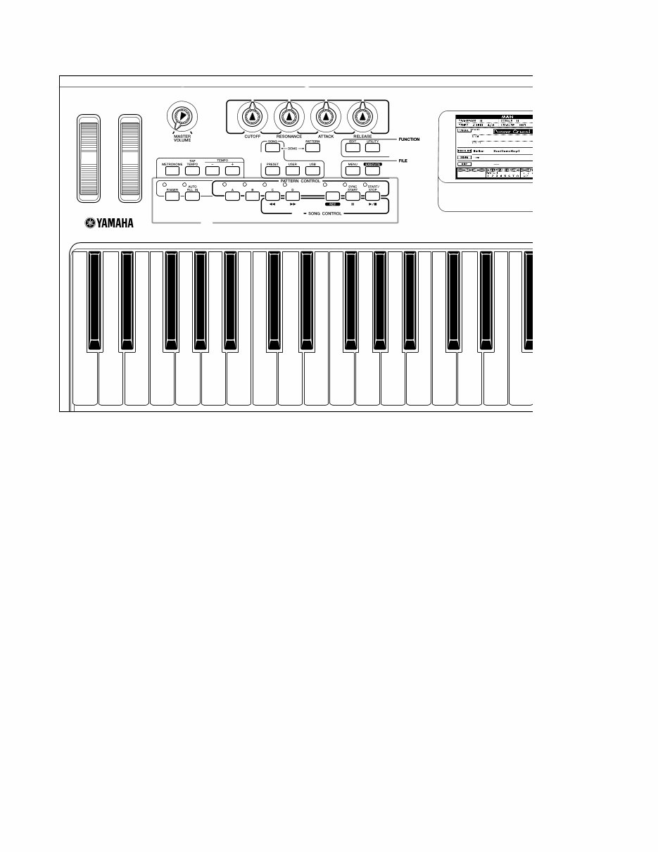
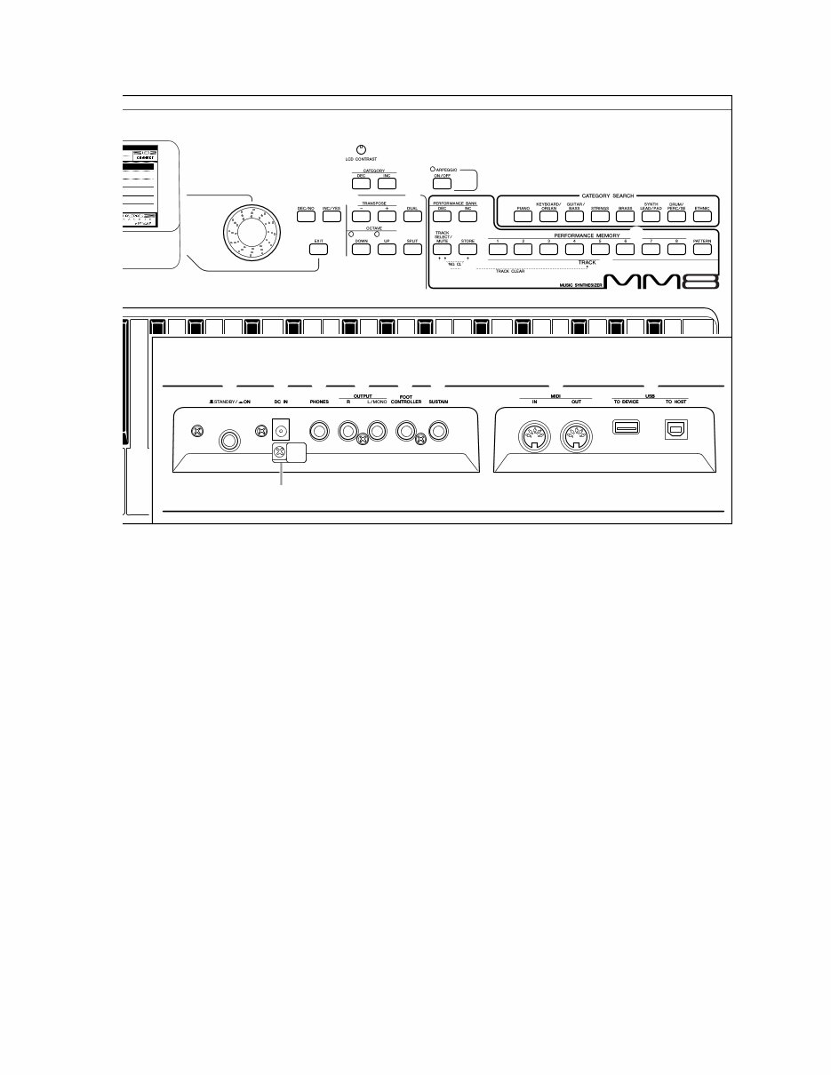
6 MM8 ■ PANEL LAYOUT(パネルレイアウト) q w r e t y u i o !0 !1 !4 !2 !3 q [PITCH BEND] wheel w [MODULATION] wheel e [MASTER VOLUME] control r [CUTOFF], [RESONANCE], [ATTACK], [RELEASE] knobs t [METRONOME] button y [TAP TEMPO] button u TEMPO [+] [-] buttons i SONG [SONG], [PRESET], [USER], [USB] buttons o [PATTERN] button !0 FUNCTION [EDIT], [UTILITY] buttons !1 FILE [MENU], [EXECUTE] buttons !2 PATTERN CONTROL [FINGER], [AUTO FILL IN], [A]-[D], [SYNC START], [START/STOP] buttons !3 SONG CONTROL [ r ] (REW), [ f ] (FF), [REC], [ ❙❙ ] (PAUSE), [ /■ ] (START/STOP) buttons !4 Display !5 Dial !6 [INC/YES], [DEC/NO] buttons !7 [EXIT] button !8 LCD CONTRAST knob !9 CATEGORY [INC], [DEC] buttons q [PITCH BEND] ホイール w [MODULATION] ホイール e [MASTER VOLUME] コントロール r [CUTOFF], [RESONANCE], [ATTACK], [RELEASE] ノブ t [METRONOME] ボタン y [TAP TEMPO] ボタン u TEMPO [+] [-] ボタン i ソング [SONG], [PRESET], [USER], [USB] ボタン o [PATTERN] ボタン !0 ファンクション [EDIT], [UTILITY] ボタン !1 ファイル操作 [MENU], [EXECUTE] ボタン !2 パターンコントロール [FINGER], [AUTO FILL IN], [A]~[D], [SYNC START], [START/STOP] ボタン !3 ソングコントロール [ r ] (巻戻し), [ f ] (早送り), [REC], [ ❙❙ ] (一時停止), [ /■ ] (スタート/ストップ) ボタン !4 画面 !5 ダイアル !6 [INC/YES], [DEC/NO] ボタン !7 [EXIT] ボタン !8 LCD CONTRAST 調節ノブ !9 CATEGORY [INC], [DEC] ボタン Front Panel フロントパネル
7 MM8 !5 !7 !6 !8 !9 @0 @5 @7 @8 @9 @6 #0 @2 #1 #3 #4 #5 #6 #7 #8 #2 @4 @3 @1 #9 @0 [ARPEGGIO ON/OFF] button @1 TRANSPOSE [+], [-] buttons @2 OCTAVE [UP], [DOWN] buttons @3 [DUAL] button @4 [SPLIT] button @5 PERFORMANCE BANK [INC], [DEC] buttons @6 PERFORMANCE MEMORY [1]-[8] buttons @7 [TRACK SELECT/MUTE] button @8 [STORE] button @9 TRACK [1]-[8], [PATTERN] buttons #0 CATEGORY SEARCH buttons #1 [STANDBY/ON] switch #2 DC IN jack #3 PHONES jack #4 OUTPUT R, L/MONO jacks #5 FOOT CONTROLLER jack #6 SUSTAIN jack #7 MIDI IN, OUT terminals #8 USB TO DEVICE, TO HOST terminals #9 Cable clip Rear Panel Rear Panel @0 [ARPEGGIO ON/OFF] ボタン @1 TRANSPOSE [+], [-] ボタン @2 OCTAVE [UP], [DOWN] ボタン @3 [DUAL] ボタン @4 [SPLIT] ボタン @5 PERFORMANCE BANK [INC], [DEC] ボタン @6 PERFORMANCE MEMORY [1]~[8] ボタン @7 [TRACK SELECT/MUTE] ボタン @8 [STORE] ボタン @9 TRACK [1]~[8], [PATTERN] ボタン #0 カテゴリーサーチボタン #1 [STANDBY/ON] スイッチ #2 DC IN 端子 #3 PHONES 端子 #4 OUTPUT R, L/MONO 端子 #5 FOOT CONTROLLER 端子 #6 SUSTAIN 端子 #7 MIDI IN, OUT 端子 #8 USB TO DEVICE, TO HOST 端子 #9 電源コードフック リアパネル
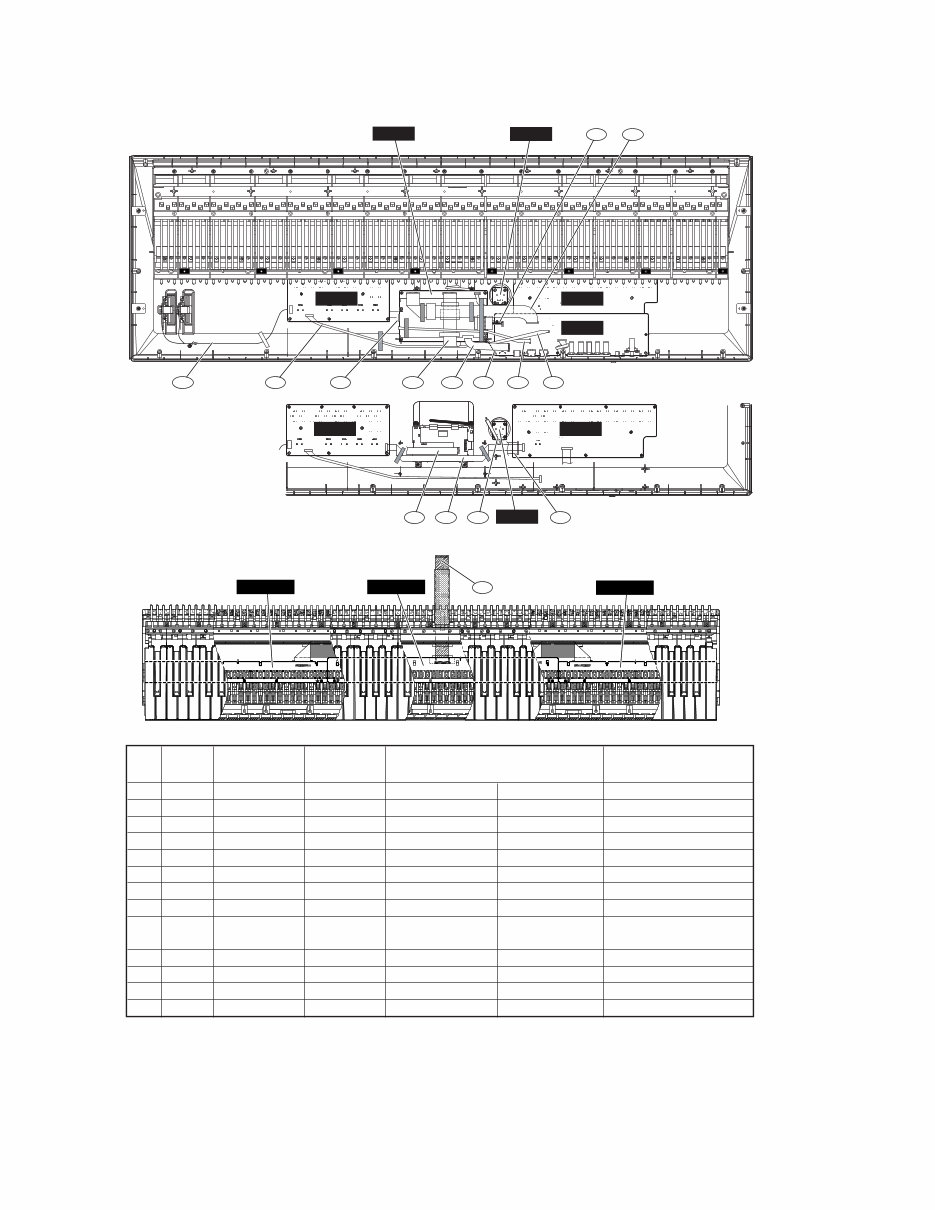
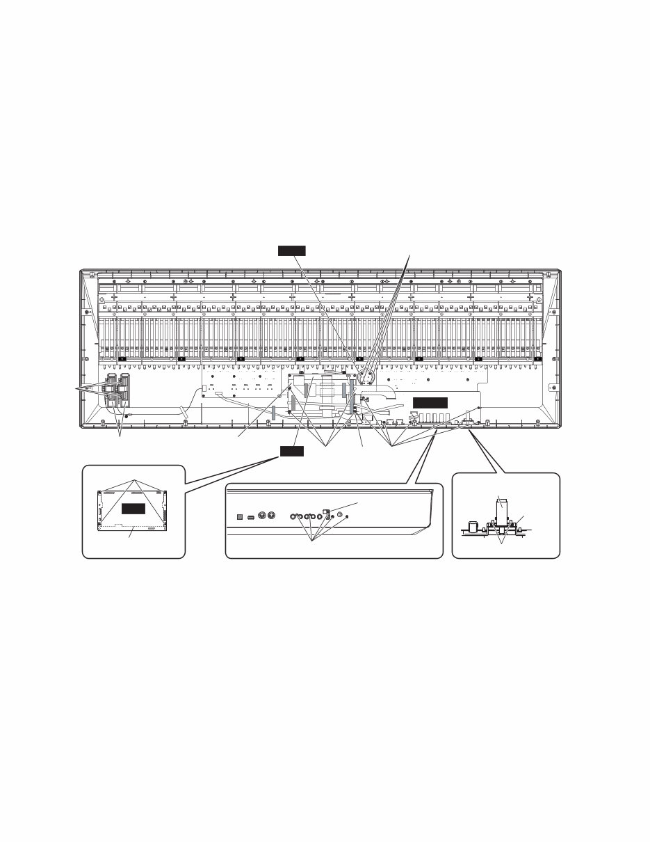
8 MM8 ■ CIRCUIT BOARD LAYOUT & WIRING (ユニットレイアウト及び結線図) ENC PNR AMJK PNL 6 4 1 5 2 12 11 13 8 10 3 9 7 *1: The parts with "( )" in "Part No." are not available as service parts. (上記束線のうち、部品No.に"( )"がついている部品は、サービス部品として準備されていません。) *2: Edge mark is adjusted to pin 1 mark( mark).(エッジマークを1ピン側(マーク)に合わせます。) *3: The conductor of a cable and the point of contact of a connector are united. (電線の導体とコネクタの接点を合わせます。) *4: Fit it to the polarity of the connector.(コネクタの極性に合わせます。) *5: Connected.(接続済み) *6: Fasten a screw.(ねじ締め) • Upper Case Assembly(上ケースAss'y) • Keyboard Assembly(GHL鍵盤Ass'y) GHL88H GHL88M GHL88L <Top view> <上から見た図 > <Bottom view> <下から見た図 > No. Ref. Part No. Assembly Destination Remarks No. (パーツNo.) (束線) (行き先) (備考) 1 90 WN331600 FFC PNR-CN101 *3 DM-CN703 *3 30P P=1.0 2 100 WN328100 FFC PNR-CN102 *3 PNL-CN201 *3 20P P=1.0 3 PNR-10 (WN33140) PNR PNR-CN103 *5 AMJK-CN403 *2 7P L=190 4 110 WH609300 VOR PNL-CN203 *4 AMJK-CN203 *4 8P L=550 5 WHEEL-90 WK597900 WHEEL PNL-CN202 *4 WHEEL *5 5P 6 ENC-20 (WH60910) ENC ENC-CN301 *5 DM-CN702 *2 3P P=2.0 7 KBD-2 WK443800 FFC DM-CN801 *2 KEYBOARD *5 27P P=1.0 8 LCD WK443800 FFC DM-CN601 *3 LCD *5 14P 9 180 WH609200 LCD AMJK-CN202 LCD *5 2P P=2.0 +: Red, -: White 10 240 WN331200 FFC AMJK-CN201 *3 DM-CN901 *3 27P P=1.0 11 250 WH590200 FFC AMJK-CN404 *3 DM-CN501 *3 14P P=1.0 12 260 WH590300 FFC AMJK-CN301 *3 DM-CN701 *3 7P P=1.0 13 AMJK-10 (WJ58570) GND AMJK-W401 *5 SHIELD COVER U *6 1P DM 7 PNR PNL ENC 8
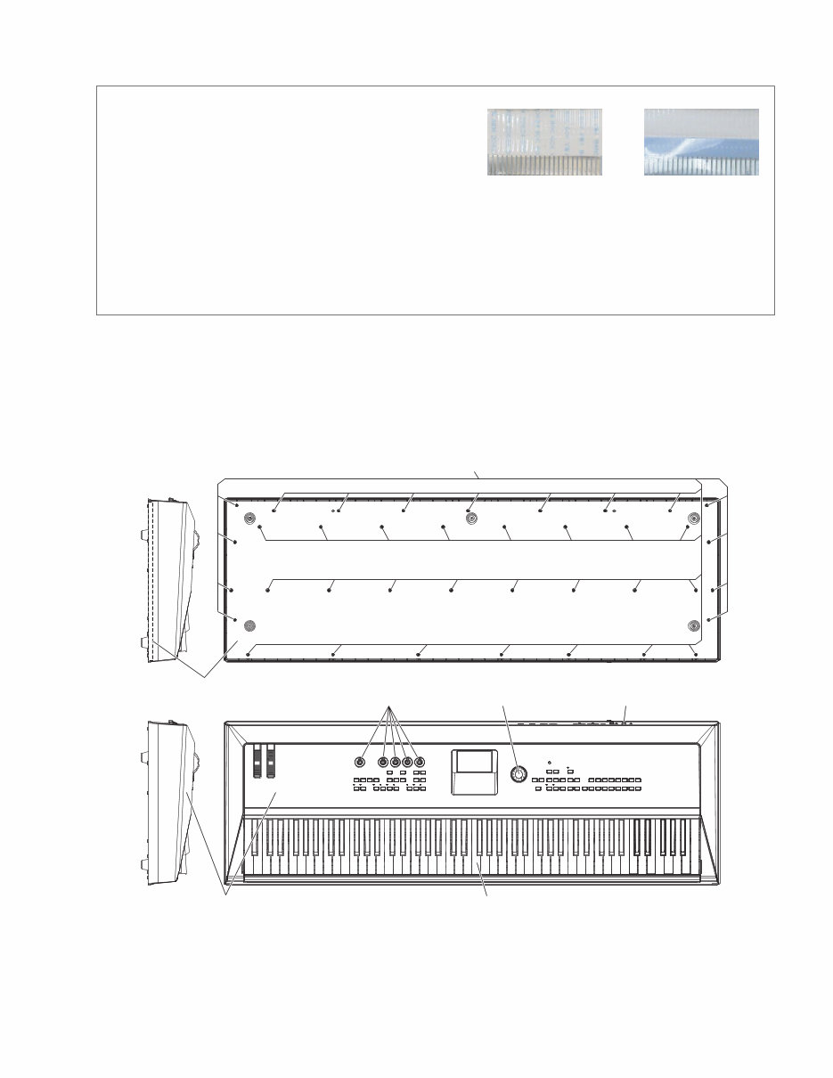
9 MM8 ■ DISASSEMBLY PROCEDURE(分解手順) Fig.1(図 1) (注意): • 一度剥がしたフィラメントテープは、取り外す前と同じよう に、取り付けてください。 • フラットケーブルの接点が裏側から透けて見えます。コネクタ にケーブルの表、裏を逆に差し込まないように注意して取り付 けてください。(図1) CAUTION: • Be sure to attach the removed filament tape just as it was before removal. • Contacts are visible from the back. Pay attention not to insert and install the cable to the connector inversely. (Fig.1) Front Side (Printed Side) (表面(印刷面)) Back Side (裏面) 1. Bottom Board Assembly (Time required: About 7 minutes) 1-1 Turn the main unit upside down, and put bolsters under both sides to make gap between the panel knobs/buttons and the panel. 1-2 Remove the thirty eight (38) screws marked [360]. The bottom board assembly can then be removed. (Fig.2) 1. 底板Ass'y (所要時間: 約7分) 体を さまにし、パネル ツマミ、ボタン を し い 為に、 右に を きます。 [ ] ネジ を し、 Ass yを します。( ) Fig.2(図 2) [360] Bottom Board Assembly (底板Ass'y) Keyboard Assembly (GHL鍵盤Ass'y) Push Knob (STANDBY/ON) (プッシュツマミ) Upper Case Assembly (上ケースAss'y) Rorary Knob (ロータリーノブ) Encoder Knob (エンコーダツマミ) [360]: BIND HEAD TAPPING SCREW-B 4.0X25 MFZN2W3 (WJ011400) Bタイト+BIND
10 MM8 2. DM Circuit Board (Time required: About 9 minutes) 2-1 Remove the bottom board assembly. (See procedure 1.) 2-2 Remove the four (4) screws marked [130A]. Both the DM circuit board(with the shield cover L) and the shield cover U can then be removed. (Fig.3) * As for the screw marked [130A] at the location of "A", it is tightened together with a GND terminal. 2-3 Remove the four (4) screws marked [130B]. The DM circuit board and the shield cover can then be separated. (Fig.3) * When installing the DM circuit board, tighten the four (4) screws marked [130B] first. (Fig.3) 2. DMシート(所要時間: 約9分) Ass yを します。( ) [ A] ネジ を し、DMシート(シールドカバー ) シールドカバー を します。( ) A 位 [ A] ネジ 、GND めされて います。 [ B] ネジ を し、DMシートシールドカバーを します。( ) DMシートを り ける 、 [ B] ネジ を に めて さい。( ) Power Switch (STANDBY/ON) (電源スイッチ) [30] PSW Angle (PSWアングル) [130B] Shield Cover L (シールドカバー下) AMJK [130A] [130D] A Shield Cover U (シールドカバー上) DM [380] [130F] Wheel Assembly (ホイールAss'y) ENC [130E] C DM Fig.3(図3) [30]: BIND HEAD SCREW 3.0X6 MFZN2W3 (WE774000) 小ネジ+BIND [130]: BIND HEAD B-TIGHT SCREW 3.0X8 MFZN2W3 (WE774300) Bタイト+BIND [380]: BIND HEAD TAPPING SCREW-B 3.0X12 MFZN2B3 (WE99810R) Bタイト+BIND 3. LCD Unit (Time required: About 10 minutes) 3-1 Remove the bottom board assembly. (See procedure 1.) 3-2 Remove the DM circuit board. (See procedure 2.) 3-3 Remove the four (4) screws marked [130C]. The LCD unit can then be removed. (Fig.4) * As for the screw marked [130C] at the location of "B", it is tightened together with a wire clip. 3. 液晶ユニット(所要時間: 約10分) Ass yを します。( ) DMシートを します。( ) [ C] ネジ を し、液 ユニットを します。( ) B 位 [ C] ネジ 、 め めされて います。
This comprehensive service manual provides detailed specifications, parts list, exploded views, and circuit board diagrams essential for repairing and servicing Yamaha products. It is an invaluable resource for both professional mechanics and DIY enthusiasts.
The manual covers a wide range of topics including specifications, panel layout, circuit board layout, block diagram, disassembly procedure, LSI pin description, IC block diagram, inspection, MIDI implementation chart, overall circuit diagram, and parts list.
Featuring high-resolution images and step-by-step instructions, this official manual ensures the best possible repair and service for your device.
Instant access to the manual is available after payment, eliminating the need for shipping and allowing for immediate commencement of repairs.
Language: English
Format: PDF
Platform: Windows, MAC, Linux, etc.
If you require service manuals for other Yamaha products, feel free to inquire!