

Service Manual HARMAN KARDON CDR30 Dual Tray CD/CD-R/CD-RW Recorder/Player
What's Included?
Fast Download Speeds
Online & Offline Access
Access PDF Contents & Bookmarks
Full Search Facility
Print one or all pages of your manual

harman/kardon
Model CDR30
Dual Tray CD/CD-R/CD-RW Recorder/Player
SERVICE MANUAL
CONTENTS
SERVICING PRECAUTIONS . . . . . . . . ... . . .. .2
ESD PRECAUTIONS..…………………………... 4
SPECIFICATIONS . . . . . . . . . . . . . . . . . . . .. . . .5
FRONT PANEL CONTROLS ……….. . . .. . . .. . 6
FRONT PANEL DISPLAY ……….. . . .. . . . . . . 8
REAR PANEL CONNECTIONS. . . . . . ……… 10
REMOTE CONTROL FUNCTIONS. . . . . .. .. …11
INSTALLATION/CONNECTIONS. ……………..13
BASIC TROUBLESHOOTING GUIDE………... 15
SPECIAL NOTES ON CDR30 RECORDING….16
DETAILED TROUBLESHOOTING GUIDE …….17
BLOCK DIAGRAMS . . . . . . . . .. . . .. . .. .. . . . .34
EXPLODED VIEWS . . . . . . . . . . . .. . .. . .. . . . . 37
MECHANICAL PARTS LIST……….. .. . . . . . .. . 40
ELECTRICAL PARTS LIST . . . . . .. . . ..… …….42
PCB DRAWINGS. . . . . . . . . . . . ….. . .. . . . .. . . 61
SCHEMATIC DIAGRAMS . . . . . ……………….. 71
WIRING DIAGRAM………………………………..88
PACKAGE………………………………………….90
harman/kardon, Inc.
250 Crossways Park Dr.
Woodbury, New York 11797 Rev0 2/2004

SERVICING PRECAUTIONS
NOTES REGARDING HANDLING OF THE PICK-UP
1. Notes for transport and storage
1) The pick-up should always be left in its conductive bag until immediately prior to use.
2) The pick-up should never be subjected to external pressure or impact.
2. Repair notes
1) The pick-up incorporates a strong magnet, and so should never be brought close to magnetic materials.
2) The pick-up should always be handled correctly and carefully, taking care to avoid external pressure and
impact. If it is subjected to strong pressure or impact, the result may be an operational malfunction
and/or damage to the printed-circuit board.
3) Each and every pick-up is already individually adjusted to a high degree of precision, and for that reason
the adjustment point and installation
screws should absolutely never be touched.
4) Laser beams may damage the eyes!
Absolutely never permit laser beams to enter the eyes!
Also NEVER switch ON the power to the laser output part (lens, etc.) of the pick-up if it is damaged.
5) Cleaning the lens surface
If there is dust on the lens surface, the dust should be cleaned away by using an air bush (such as used
for camera lens). The lens is held by a delicate spring. When cleaning the lens surface, therefore, a cot-
ton swab should be used, taking care not to distort this.
6) Never attempt to disassemble the pick-up.
Spring by excess pressure. If the lens is extremely dirty, apply isopropyl alcohol to the cotton swab. (Do
not use any other liquid cleaners, because they will damage the lens.) Take care not to use too much of
this alcohol on the swab, and do not allow the alcohol to get inside the pick-up.
Storage in conductive bag
NEVER look directly at the laser beam, and don’t let contact
fingers or other exposed skin.
Magnet
How to hold the pick-up
Conductive Sheet
Cotton swab
Pressure
Pressure
Drop impact
CDR30 harman/kardon
2

NOTES REGARDING COMPACT DISC PLAYER REPAIRS
1. Preparations
1) Compact disc players incorporate a great many ICs as well as the pick-up (laser diode). These compo-
nents are sensitive to, and easily affected by, static electricity. If such static electricity is high voltage,
components can be damaged, and for that reason components should be handled with care.
2) The pick-up is composed of many optical components and other high-precision components. Care must
be taken, therefore, to avoid repair or storage where the temperature of humidity is high, where strong
magnetism is present, or where there is excessive dust.
2. Notes for repair
1) Before replacing a component part, first disconnect the power supply lead wire from the unit
2) All equipment, measuring instruments and tools must be grounded.
3) The workbench should be covered with a conductive sheet and grounded.
When removing the laser pick-up from its conductive bag, do not place the pick-up on the bag. (This is
because there is the possibility of damage by static electricity.)
4) To prevent AC leakage, the metal part of the soldering iron should be grounded.
5) Workers should be grounded by an armband (1MΩ)
6) Care should be taken not to permit the laser pick-up to come in contact with clothing, in order to prevent
static electricity changes in the clothing to escape from the armband.
7) The laser beam from the pick-up should NEVER be directly facing the eyes or bare skin.
Resistor
(1 Mohm)
Conductive
Sheet
Resistor
(1 Mohm)
Armband
CDR30 harman/kardon
3

ESD PRECAUTIONS
Electrostatically Sensitive Devices (ESD)
Some semiconductor (solid state) devices can be damaged easily by static electricity. Such components com-
monly are called Electrostatically Sensitive Devices (ESD). Examples of typical ESD devices are integrated cir-
cuits and some field-effect transistors and semiconductor chip components. The following techniques should
be used to help reduce the incidence of component damage caused by static electricity.
1. Immediately before handling any semiconductor component or semiconductor-equipped assembly, drain off
any electrostatic charge on your body by touching a known earth ground. Alternatively, obtain and wear a
commercially available discharging wrist strap device, which should be removed for potential shock reasons
prior to applying power to the unit under test.
2. After removing an electrical assembly equipped with ESD devices, place the assembly on a conductive sur-
face such as aluminum foil, to prevent electrostatic charge buildup or exposure of the assembly.
3. Use only a grounded-tip soldering iron to solder or unsolder ESD devices.
4. Use only an anti-static solder removal device. Some solder removal devices not classified as "anti-static"
can generate electrical charges sufficient to damage ESD devices.
5. Do not use freon-propelled chemicals. These can generate electrical charges sufficient to damage ESD
devices.
6. Do not remove a replacement ESD device from its protective package until immediately before you are
ready to install it. (Most replacement ESD devices are packaged with leads electrically shorted together by
conductive foam, aluminum foil or comparable conductive materials).
7. Immediately before removing the protective material from the leads of a replacement ESD device, touch the
protective material to the chassis or circuit assembly into which the device will by installed.
CAUTION : BE SURE NO POWER IS APPLIED TO THE CHASSIS OR CIRCUIT, AND OBSERVE ALL
OTHER SAFETY PRECAUTIONS.
8. Minimize bodily motions when handing unpackaged replacement ESD devices. (Otherwise harmless motion
such as the brushing together of your clothes fabric or the lifting of your foot from a carpeted floor can gen-
erate static electricity sufficient to damage an ESD device).
CDR30 harman/kardon
4

SPECIFICATIONS
Playback Sampling Frequency 44.1 kHz
D/A Conversion 96kHz, Multi-Bit Delta-Sigma Conversion
Oversampling 128 Times
Playback Specifications
Frequency Response 2Hz – 20,050Hz
Playback S/N 100dB
Playback Dynamic Range 100dB
Playback THD 0.005% / –88dB
Analog Audio Output 1V RMS, ± 2dB (1KHz 0dB)
Digital-Coaxial Output 0.5 Vpp/75Ω
Headphone Output 0.5V RMS/32Ω Load (1KHz 0dB)
Record Specifications
Digital Dubbing Mode(X1/X2/X4) Equal to source
Digital Input Sample Rate 32kHz ~ 96kHz
Signal/Noise Ratio - Analog 91dB
Signal/Noise Ratio - External(Source) source -10dB
Dynamic Range 91dB
THD 0.005%/-85dB
Analog Input Sensitivity 330 mV RMS 47kΩ = 0dB
Digital Inputs (Direct Recording) 44.1kHz, ± 100 ppm/min.
General
Power Requirement 100~240V AC, 50/60Hz
Power Consumption 26 Watts
Dimensions
Width 17.3" (440mm)
Height 4.4" (112mm)
Depth 14.2" (363mm)
Weight 10.6 lbs (4.8 kg)
Depth measurement includes knobs, buttons and connection jacks.
Height measurement includes feet and chassis.
All features and specifications are subject to change without notice.
CDR30 harman/kardon
5

1 Power Switch: Press this switch to apply
power to the CDR 30. When the unit is first
turned on, the Standby Mode Indicator 2
surrounding the switch will turn green. Once
the unit has been turned on with this switch, it
may be operated from either the front panel or
remote control. Press the switch again to turn
the unit completely off.
2 Standby Mode Indicator: When the
CDR 30 is in the ON mode, this indicator will
glow green. When the unit has been placed in
the Standby mode by pressing the Power-Off
Button on the remote, the indicator will
glow amber, indicating that the unit is still
connected to the AC main supply and may be
turned on from the remote control.
3 Play (CDP) Deck: This disc drawer is used
to play back conventional CD discs, MP3 discs
and CD-R or CD-RW discs that have been
finalized.
4 Headphone Jack: Connect standard head-
phones to this jack for private listening.
5 Headphone Level Control: Turn this
control to adjust the volume level to the head-
phones. Note that the use of this control will
not change the analog output levels at the rear
panel audio outputs ¡™.
6 Play Deck (CDP) Open/Close: Press this
button to open the Play Deck 3.
7 Record Button: Press this button to begin
the recording process. See pages 21–25 for
more information on CD recording.
8 Sync Record Button: Press this button
once to begin an automated recording of a sin-
gle track from an external CD player when a
digital connection is used. Press it twice to
begin automated recording of an entire disc.
See page 22 for more information on CD Sync
recording.
9 1 Track Dub Button: Press this button to
begin the process of copying a single track from
the CDP deck to a CD-R or CD-RW disc in the
CDR deck.
) Dubbing Button: Press this button to
begin the process of making a complete copy
of the disc in the Play Deck 3 to a CD-R or
CD-RW disc in the Record Deck %. See
page 21 for more information on dubbing.
! Speed Select Button: Press this button
to select the recording speed for internal dubs.
See page 21 for more information on selecting
the proper speed.
@ Erase Button: Press this button to erase
one or more tracks or the entire contents of an
unfinalized CD-RW disc. When a CD-RW disc
has already been finalized you may erase the
entire disc or you may “unfinalize” the disc by
erasing the TOC data. See page 24 for more
information on erasing CD-RW discs.
29
Front Panel Controls
1 Power Switch
2 Standby Mode Indicator
3 Play (CDP) Deck
4 Headphone Jack
5 Headphone Level Control
6 Play (CDP) Open/Close
7 Record Button
8 Sync Record Button
9 1 Track Dub Button
) Dubbing Button
! Speed Select Button
@ Erase Button
# Finalize Button
$ Record (CDR) Deck Open/Close
% Record (CDR) Deck
^ Optical Digital Input
& Coaxial Digital Input
* Analog Record Level Control
( CDR Play/Select Button
Ó CDR Deck Stop
Ô CDR Deck Pause
Digital Level Controls
Ò MP3 Select Button
Ú CDR Deck Program Button
Û CDR Deck Next Track Button
Ù CDR Deck Previous Track Button
ı Input Select
ˆ CDR Deck Display Select
˜ Information Display
¯ Remote Sensor
˘ CDP Deck Display Select
¸ Dual/Single Play Select
˝ CDP Next Track
CDP Deck Previous Track
CDP Deck Program
CDP Deck Pause Button
CDP Deck Play Button
CDP Deck Stop Button
STOP
CDR 30
PLAY PAUSE PROGRAM PREV. NEXT DUAL DISPLAY DISPLAY INPUT PREV. NEXT PROGRAM PAUSE
MP3 DIG. REC
PLAY/SELECT STOP Record
Power Phones Phones Level Optical In Digital In Analog Rec. Level
Sync Rec. 1 Trk. Dub Dubbing Speed Erase Finalize
2
1 3 5 6
7
8
9
)
! #
@ $ %
* & ^
4
Ó
Ú
Û
Ù
ı
ˆ
˜
¯ ¸
˝ ˘
Ô
Ò
(
CDR30 harman/kardon
6

Front Panel Controls
# Finalize Button: Press this button when a
recording is complete to initiate the finalization
process. The Play/Select Button ( must
be pressed within three seconds to activate
finalization. Until this button is pressed and the
finalization process is complete, CD-R discs may
not be played on conventional CD machines.
See page 23 for more information on finaliza-
tion.
$ Record (CDR) Deck Open/Close: Press
this button to open the Record Deck %.
% Record (CDR) Deck: This Disc Deck is
used to record or play back CD, MP3, CD-R and
CD-RW discs.
^ Optical Digital Input: This jack accepts
the digital audio input signal from a compatible
digital audio product and should be connected
directly to the optical digital audio output on a
CD or DVD player or an A/V receiver or proces-
sor. To select this input, press the Input Select
Button ı until OPTICAL DIGITAL
appears in the Time/Message Display F.
Note that the cover with the “eye” icon must
be removed before the input is used. Save the
cover and replace it when the jack is not in use
to prevent dust from entering the jack and
degrading the input’s performance.
& Coaxial Digital Input: This input may be
used to connect a portable digital audio player
to the CDR 30 for digital recording. To select this
input, press the Input Select Button ı until
COAXIAL DIGITAL appears in the
Time/Message Display F.
* Analog Record Level Control: The control
is used to adjust the input level when making
recordings from analog sources such as cassettes,
or when CDs are recorded in an analog mode.
See page 23 for more information on record levels.
( CDR Play/Select Button: This button has
two functions. It may be pressed when a stan-
dard CD is in the Record Deck to put the
machine in play, or it may be used to enter a
selection or start certain record functions.
Ó CDR Deck Stop: Press this button to stop
the CD in the Record Deck.
Ô CDR Deck Pause Button: When the
Record Deck is in the Play mode, pressing this
button will pause the disc. If the disc has previ-
ously been paused, pressing this button will
restart the playback.
Digital Level Controls: These buttons
raise or lower the record level when a digital
recording is being made. Pressing both buttons
briefly and then release them to change from
manual to automatic digital recording level
control. See page 23 for more information on
digital recording levels.
Ò MP3 Select Button: When a “Multisession”
disc containing both standard CD audio and
MP3 tracks is playing, the unit will default to
play of the standard CD audio tracks. Press this
button to play the MP3 tracks.
Ú CDR Deck Program Button: Press this
button to begin the programming sequence for
a disc in the CDR deck. See page 19 for more
information on programmed playback.
Û CDR Deck Next Track: When a disc is
playing in the Record Deck %, press and hold
this button to play the disc in a fast-forward
mode to quickly locate a desired passage. At any
time, tapping the button and quickly releasing it
will move to the next track on a disc in play.
Ù CDR Deck Previous Track: This button
has two functions. When a disc is playing in the
Record Deck %, press and hold this button
to play the disc in a fast reverse mode to quickly
locate a desired passage. At any time, tapping
the button and quickly releasing it will move to
the beginning of the current track, and the next
press will move to the previous track. When a
disc is stopped, each press will move back one
for programming or play when the disc is stopped.
Once a track is entered, it may be played by
simply pressing the Play Button (j.
ı Input Select: Press this button to select
the input source (coaxial rear, optical rear, coaxial
front, optical front and analog) for recording.
See page 23 for more information on input
selection.
ˆ CDR Deck Display Select: Press this
button to cycle through the time display options
for the Record Deck. See page 18 for more
information on the time display.
˜ Information Display: The indicators in
the Information Display provide status reports
on the operation of the CDR 30. See page 7 for
complete explanations of each indicator.
¯ Remote Sensor: The IR sensor that
receives the commands from the remote control
is behind this area. Do not cover or obscure this
part of the front panel to avoid any malfunction
with the remote.
˘ CDP Deck Display Select: Press this but-
ton to cycle through the time display options
for the Play Deck. See page 18 for more infor-
mation on the time display.
¸ Dual/Single Play Select: Press this but-
ton to enable both CD decks to play at the
same time and function as separate, independ-
ent CD units or to have the unit play through
all the tracks on the disc in one deck and then
switch to the other. In the Dual mode it is also
possible to record from an external source in
the CDR while the CDP Deck is functioning as a
standard CD player. See page 18 for more infor-
mation on dual-play capability.
˝ CDP Deck Next Track: When a disc is
playing in the Play Deck 3, press and hold
this button to play the disc in a fast-forward
mode to quickly locate a desired passage.
At any time, tapping the button and quickly
releasing it will move to the next track on a
disc in play.
CDP Deck Previous Track: This button
has two functions. When a disc is playing in the
Play Deck 3, press and hold this button to
play the disc in a fast-reverse mode to quickly
locate a desired passage. At any time, tapping
the button and quickly releasing it will move to
the beginning of the current track, and the next
press will move to the previous track. When a
disc is stopped, each press will move back one
track for programming or play when the disc is
stopped. Once a track is entered, it may be
played by simply pressing the Play Button
j.
CDP Deck Program Button: Press this
button to begin the programming sequence for
a disc in the CDR deck. See page 19 for more
information on programmed playback.
CDP Deck Pause: When the CDP Deck is
running, pressing this button will pause the
disc. If the disc has previously been paused,
pressing this button will restart the playback.
CDP Deck Play Button: Press this button
to begin playback of a CD in the CDP Deck.
CDP Deck Stop Button: Press this button
to stop the CD in the CDP Deck.
CDR30 harman/kardon
7
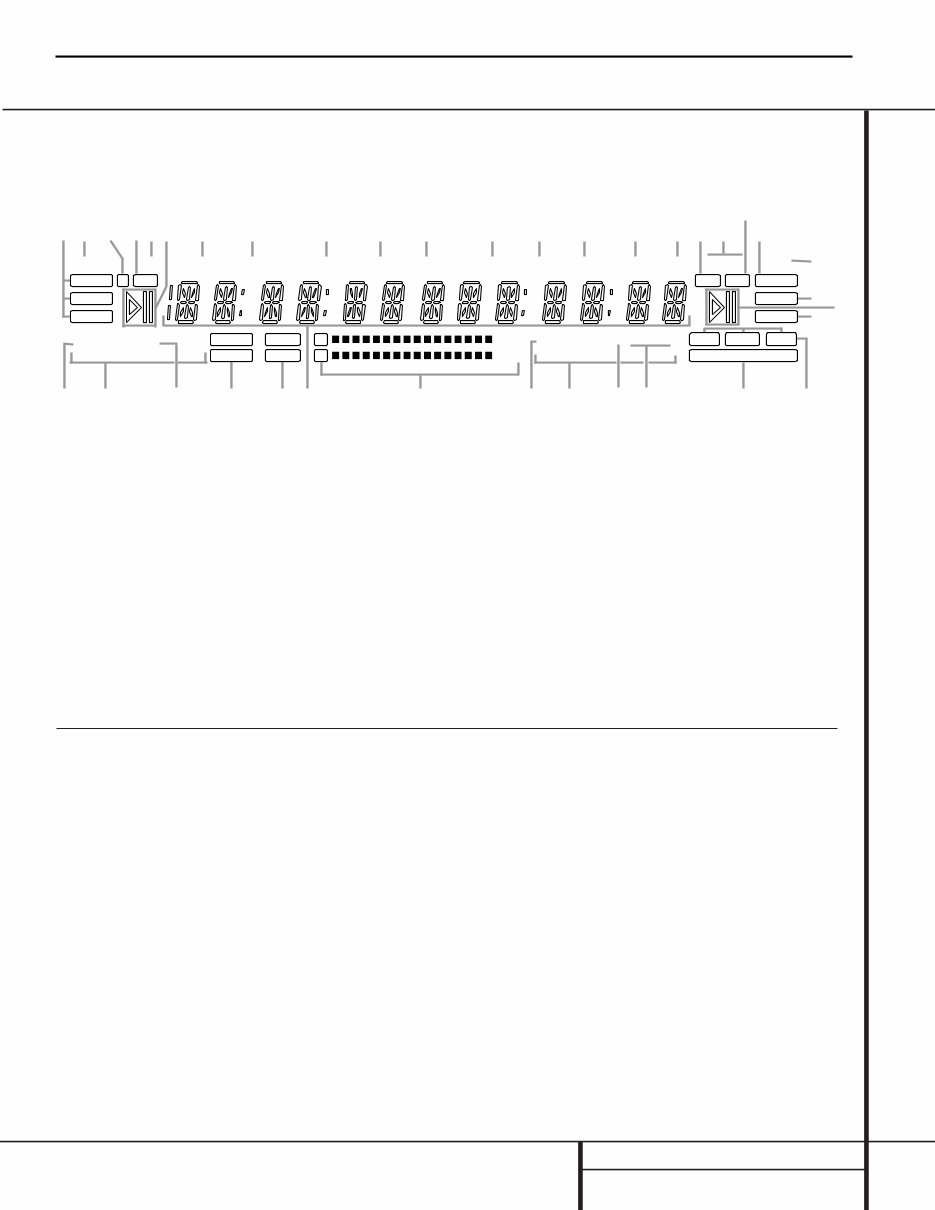
Front Panel Information Display
MP3
CD HDCD
RANDOM PROG
REPEAT 1 A–B
RANDOM PROG
REPEAT1 A–B
OVER X2 X4
OVER ALL CD’S ALL CD’S
HDCD TRACK TRACK TOTAL TOTAL TIME CD–RW REMAIN REC REMAIN TIME A DRLC
MP3 SRC F OPTICAL
COAXIAL
ANALOG
RECORD
SYNC
MANUAL
DUAL COPY PROHIBIT CDR
CDP I T R DUB DISC
R
L SINGLE
A A B B C C D EF G I H J
L
M
N
O
P
Q R S T U V V W W X YP S T Q N Z
K
L
A Random Indicator
B Repeat Mode Indicators
C Program Indicator
D Single/Dual Play Indicators
E CDP/CDR Deck Indicator
F Time/Message Display
G Level Indicators
H Dub Speed Indicators
I Copy Prohibit Indicator
J Dub Mode Indicators
K Manual Track Increment Indicator
L Play/Pause Indicators
M CD Sync Indicator
N HDCD Indicators
O Record Indicator
P MP3 Playback Indicator
Q CDR/RW Indicator
R Sample-Rate Converter Indicator
S Time Indicators
T Remaining Time Indicators
U Record Time Indicator
V Total Time Indicators
W Track Time Indicators
X Digital Record Level Status Indicator
Y Front Input Indicator
Z Input Indicators
Important Note: Since the CDR 30 is a dual-deck player/recorder, there are two separate sets of indicators for the Random, Program, Repeat, Repeat
Status, Time, Total Time, Track Time. Play/Pause Indicator and CD Indicators for each deck. As the function of these indicators is identical for both decks,
they are described in this manual with a common letter. When the CDR 30 is playing or recording a disc, any indicators that light on the left side of the
display describe the status of the Play Deck, while those that light on the right side of the display describe the status of the Record Deck. Depending on
the activity of the unit and the settings you select, different indicators may light on the two sides at the same time.
A Random Indicators: These indicators light
when random playback has been programmed
for one of the decks. See page 19 for more
information on random play.
B Repeat Mode Indicators: These indica-
tors display the type of repeat function being
used. See page 19 for more information on
repeat status.
C Program Indicators: These indicators
light when one of the decks is being programmed
for playback options. See page 19 for more
information on programmed play.
D Single/Dual Play Indicators: One of
these indicators will light to indicate the unit’s
playback mode, as selected with the Dual/Single
Play Select Buttons ¸gx. When the
Dual indicator lights, both decks will play
simultaneously to through their respective
analog or digital outputs. When the SINGLE
indicator is lit, only one deck may play at a
time, but the unit will automatically switch
from one side to the other when a deck is
finished playing.
E CDP/CDR Deck Indicator: These indica-
tors show if the Level Indicators G are
showing the output of the record (CDR) or
play (CDP) deck.
F Time/Message Display: This display
shows the play or record time for either deck,
as noted by the various time and mode indica-
tors STUVW. It also displays the CD Text
or MP3 information from a disc and displays
various information, status and error messages.
G Level Indicators: These LEDs display the
input level during a recording, and the output
level during playback. See page 23 for more
information on record levels.
H Dub Speed Indicators: These indicators
show which record speed has been selected for
dub recordings. See page 21 for more informa-
tion on record-speed selection.
CDR30 harman/kardon
8

I Copy Prohibit Indicator: This indicator
lights when a recording is not possible
due to the intervention of the Serial Copy
Management System (SCMS). See page 20 for
more information on SCMS.
J Dub Mode Indicators: These indicators
light when a dub is in progress between the CDP
and CDR decks to confirm that either one track
(1 TR) or the entire disc (DISC) is being dubbed.
K Manual Track Increment Indicator: This
indicator lights when the automatic track incre-
ment system has been turned off. When the indi-
cator is lit, tracks may be incremented during a
recording by pressing the Track Increment
Button n.
L Play/Pause Indicators: These indicators
show the status of the individual decks. The ›
lights when the CD is playing, and the › ±
lights when either deck is in a Pause mode.
M CD Sync Indicator: This indicator lights
when the unit has been programmed for a CD
Sync recording. See page 22 for more informa-
tion on CD Sync recordings.
N HDCD Indicators: These indicators will light
when either of the decks is playing a disc that
contains HDCD encoding.
O Record Indicator: This indicator lights
when the unit is making a recording and flashes
during the preparations for recording.
P MP3 Playback Indicator: These indicators
will light when either of the decks is playing a
disc that contains MP3 data.
Q CDR/RW Indicator: This indicator shows
which type of recordable disc is present in the
Record Deck %. When a CD-R disc is present,
only the R is lit. The RW lights when an erasable
CD-RW disc is in use.
R Sample-Rate Converter Indicator: This
indicator lights when the Sample-Rate Converter
is in use to change the digital sample rate when
the incoming signal is not the standard 44.1kHz
used by standard CDs. This is an automatic func-
tion and does not require any user intervention.
S Time Indicators: These indicators light in
conjunction with one of the Time Indicators
TVW to show which of the time status
modes is active.
T Remaining Time Indicators: These indica-
tors light when the Time/Message Display F
shows the time remaining on a disc.
U Record Time Indicator: This indicator lights
in conjunction with the REMAIN T or TOTAL V
indicators during a recording to show that
the time figure shown in the Time/Message
Display F is either the time remaining on the
disc or the time elapsed for the current track.
V Total Time Indicators: These indicators
light when the Time/Message Display F
shows the total time of all tracks on a disc.
W Track Time Indicators: These indicators
light when the Time/Message Display F
shows the running time of the individual track
being played.
X Digital Record Level Status Indicator:
During a digital recording, this indicator shows
ADRLC when the record level is controlled auto-
matically, and DRLC when you may control it
manually. See page 23 for more information on
record levels.
Y Front Input Indicator: This indicator lights
when the front panel Optical Digital ^ or
Coaxial Digital & inputs are the source for
a recording.
Z Input Indicators: These indicators light to
display which input source is in use.
Front Panel Information Display
CDR30 harman/kardon
9

¡
™
£
¢
∞
§
¶
•
ª
‚
∕
¤
¡ Play (CDP)-Deck Analog Output
™ Record (CDR)-Deck Analog Output
£ Record (CDR)-Deck Analog Input
¢ Play (CDP)-Deck Coaxial-Digital Output
∞ Record (CDR)-Deck Coaxial-Digital Output
§ Record (CDR)-Deck Coaxial-Digital Input
¶ Record (CDR)-Deck Optical-Digital Input
• Record (CDR)-Deck Optical-Digital Output
ª Play (CDP)-Deck Optical-Digital Output
‚ Remote IR Input
∕ Remote IR Output
¤ AC Power Cord
¡ Play (CDP)-Deck Analog Output: These
jacks carry the analog audio output signal from
the Play Deck 3. Connect them to the CD
input jacks on a receiver, preamp or processor.
™ Record (CDR)-Deck Analog Output:
These jacks carry the output signal from the
Record Deck %. Connect them to the Tape
Play/In input jacks on a receiver, preamp or
processor.
£ Record (CDR)-Deck Analog Input: These
jacks accept the analog signals that are used
for CD recordings. Connect them to the Tape
Rec/Play outputs on a receiver, preamp or
processor.
¢ Play (CDP)-Deck Coaxial-Digital
Output: This jack carries the digital-audio out-
put signal from the Play Deck 3. Connect it
to a coaxial-digital input on a receiver, proces-
sor or digital decoder.
∞ Record (CDR)-Deck Coaxial-Digital
Output: This jack carries the digital audio out-
put signal from the Record Deck %. Connect
it to a coaxial digital input on a receiver,
processor or digital decoder.
§ Record (CDR)-Deck Coaxial-Digital
Input: This jack accepts the digital-audio input
signal from a compatible digital audio product
and should be connected directly to a digital
player or to a coaxial-digital output on a CD or
DVD player or an A/V receiver or processor.
IMPORTANT NOTE: The coaxial digital inputs
should only be connected to digital input or
output jacks. Even though they use the same
RCA-type connector as standard analog audio
connections, DO NOT connect them to conven-
tional analog input or output jacks.
¶ Record (CDR)-Deck Optical-Digital
Input: This jack accepts the digital-audio input
signal from a compatible digital audio product,
and should be connected directly to the optical-
digital output on a CD or DVD player or an A/V
receiver or processor.
• Record (CDR)-Deck Optical-Digital
Output: This jack carries the digital audio out-
put signal from the Record Deck %. Connect
it to an optical digital input on a receiver,
processor or digital decoder.
ª Play (CDP)-Deck Optical-Digital
Output: This jack carries the digital audio out-
put signal from the Play Deck 3. Connect it
to an optical-digital input on a receiver, proces-
sor or digital decoder.
‚ Remote IR Input: Connect the output of a
remote infrared sensor or the remote control
output of another compatible Harman Kardon
product to this jack. This will enable the remote
control to operate even when the front panel
Remote Sensor ¯ is blocked. This jack may
also be used with compatible IR remote control
based automation systems.
∕ Remote IR Output: Connect this jack
to the IR input jack of another compatible
Harman Kardon remote controlled product to
have the built-in Remote Sensor ¯ on the
CDR 30 provide IR signals to other compatible
products.
¤ AC Power Cord: Connect this plug to an
AC outlet. If the outlet is switch controlled,
make certain that it is in the ON position.
Rear Panel Connections
CDR30 harman/kardon
10
You're Reading a Preview
What's Included?
Fast Download Speeds
Online & Offline Access
Access PDF Contents & Bookmarks
Full Search Facility
Print one or all pages of your manual
$31.99
Viewed 64 Times Today


Secure transaction
What's Included?
Fast Download Speeds
Online & Offline Access
Access PDF Contents & Bookmarks
Full Search Facility
Print one or all pages of your manual
$31.99
Get your HARMAN KARDON CDR30 Dual Tray CD/CD-R/CD-RW Recorder/Player back in top condition with this comprehensive Service Manual. Whether you're a professional mechanic or a DIY enthusiast, this manual provides visual and step-by-step instructions for flawless repairs to your electronic items.
- Servicing Precautions
- ESD Precautions
- Specifications
- Front Panel Controls
- Rear Panel Connections
- Remote Control Functions
- Installation/Connections
- Basic Troubleshooting Guide
- Special Note on CDR30 Recording
- Detailed Troubleshooting Guide
- Block Diagrams
- Exploded Views
- Mechanical Parts List
- Electrical Parts List
- PCB Drawings
- Schematic Diagrams
- Wiring Diagrams
- Package
- PLUS MORE...
Total Pages: 234
Format: PDF
Language: English
Compatible: Win/Mac
This format allows you to print all, any, or only the pages you need. Easily print the manual in full or only the sections you wish to use. With lots of pictures and diagrams at your fingertips, you'll have everything you need to get your HARMAN KARDON CDR30 back in working order.
Email delivery means no need to wait for your manual or pay for shipping.


