

SERVICE MANUAL
1.451K-2341 Printed in Japan ’02.07
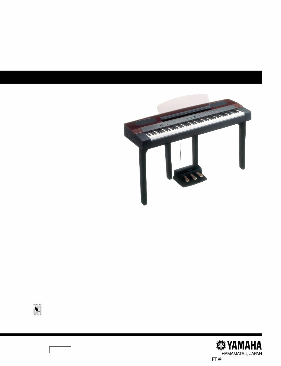
PF-500
PK 001678
■ CONTENTS
SPECIFICATIONS ....................................................... 3/4
PANEL LAYOUT .............................................. 5
DISASSEMBLY PROCEDURE ....................................... 7
LSI PIN DESCRIPTION ..................................... 20
IC BLOCK DIAGRAM .......................................... 25
CIRCUIT BOARDS ............................................... 26
TEST PROGRAM .................................... 41/44
FACTORY SET ................................................................. 48
MIDI IMPLEMENTATION CHART .................................................... 49
MIDI DATA FORMAT ........................................................................ 50
PARTS LIST
OVERALL CIRCUIT DIAGRAM
CIRCUIT BOARD LAYOUT
BLOCK DIAGRAM This document is printed on chlorine free (ECF) paper.
ELECTRONIC PIANO
このサービスマニュアルはエコパルプ�
(ECF : 無塩素系漂白パルプ)を使用しています。�
20020701-248000
(目次)
(総合仕様)
(パネルレイアウト)
(分解手順)
(LSI 端子機能表)
(IC ブロック図)
(シート基板図)
(テストプログラム)
(初期化)
(総回路図)
(ユニットレイアウト)
(ブロックダイアグラム)
PF-500
2
IMPORTANT NOTICE
This manual has been provided for the use of authorized Yamaha Retailers and their service personnel. It has been assumed
that basic service procedures inherent to the industry, and more specifically Yamaha Products, are already known and
understood by the users, and have therefore not been restated.
WARNING : Failure to follow appropriate service and safety procedures when servicing this product may result in
personal injury, destruction of expensive components and failure of the product to perform as
specified. For these reasons, we advise all Yamaha product owners that all service required should
be performed by an authorized Yamaha Retailer or the appointed service representative.
IMPORTANT : This presentation or sale of this manual to any individual or firm does not constitute authorization,
certification, recognition of any applicable technical capabilities, or establish a principal-agent
relationship of any form.
The data provided is believed to be accurate and applicable to the unit (s) indicated on the cover. The research engineering,
and service departments of Yamaha are continually striving to improve Yamaha products. Modifications are, therefore,
inevitable and changes in specification are subject to change without notice or obligation to retrofit. Should any discrepancy
appear to exist, please contact the distributor’s Service Division.
WARNING : Static discharges can destroy expensive components. Discharge any static electricity your body
may have accumulated by grounding yourself to the ground bus in the unit (heavy gauge black wires
connect to this bus).
IMPORTANT : Turn the unit OFF during disassembly and parts replacement. Recheck all work before you apply
power to the unit.
WARNING : CHEMICAL CONTENT NOTICE !
The solder used in the production of this product contains LEAD. In addition, other electrical/electronic and/or plastic
(where applicable) components may also contain traces of chemicals found by the California Health and Welfare Agency
(and possibly other entities) to cause cancer and/or birth defects or other reproductive harm.
DO NOT PLACE SOLDER, ELECTRICAL/ELECTRONIC OR PLASTIC COMPONENTS IN YOUR MOUTH FOR ANY
REASON WHAT SO EVER!
Avoid prolonged, unprotected contact between solder and your skin! When soldering, do not inhale solder fumes or expose
eyes to solder/flux vapor!
If you come in contact with solder or components located inside the enclosure of this product, wash your hands before
handling food.
IMPORTANT NOTICE FOR THE UNITED KINGDOM
Connecting the Plug and Cord
IMPORTANT . The wires in this main lead are coloured inaccordance with the following code:
BLUE: NEUTRAL
BROWN: LIVE
As the colours of the wires in the main lead of this apparatus may not correspond with the coloured markings identifying the
terminals in your plug, proceed as follows:
The BLUE wire must be connected to the terminal that is marked with the letter N (or coloured BLACK).
The BROWN wire must be connected to the terminal that is marked with the letter L (or coloured RED).
Be certain that neither core is connected to the earth terminal of the three pin plug.
■ WARNING
Components having special characteristics are marked Z and must be replaced with parts having specification equal to
those originally installed.
Z印の部品は、安全を維持するために重要な部品です。交換する場合は、安全のために必ず指定の部品をご使用ください。
PF-500
3
■ SPECIFICATIONS
Keyboard 88 keys (A-1–C7)
Sound Source AWM Dynamic Stereo Sampling
Polyphony max. 128 voices
Voice Selection Panel preset for manual performance: 38 voices,
XG voices: 480 voices + 12 drum kits
Effect Reverb, Chorus, Brilliance, Variation effect, Insertion effect x 3
Controls Dual, Split
Display LCD
Recording/Playback 16-track recording/playback, tempo adjustment
Pedal Damper, Sostenuto, Soft
Demo Songs 16 voice demo songs, 50 preset songs
Jacks/Connectors MIDI (IN/OUT/THRU), PHONES x 2, AUX IN, AUX OUT(L/L+R,R),
AUX OUT (LEVEL FIXED)(L,R), TO HOST, USB, AUX PEDAL
Main Amplifiers 30W x 2
Speakers 16cm x 2, 5cm x 2
Output Impedance AUX OUT : about 600 Ω (594 Ω)
AUX OUT (Fix) : 680 Ω
PHONES : 33 Ω
Dimensions (W x D x H) Main unit 1430mm x 507mm x 145mm [56-5/16" x 19-15/16" x 5-11/16"]
(with music stand, pedal unit) Main unit with
1430mm x 507mm x 762mm [56-5/16" x 19-15/16" x 30"]
keyboard stand
Weight Main unit 61.5 kg, 135lbs., 9oz
(with music stand, pedal unit) Main unit with
61.5 kg, 135lbs., 9oz
keyboard stand
Included Accessories Pedal Unit, Keyboard Stand, Music Stand, Bench (included or optional depending
on locale), Dust Cover (included or optional depending on locale), Owner’s
Manual, Reference Booklet, CD-ROM
PF-500
4
■ 総合仕様
鍵盤 88 鍵(A‐1 ~ C7)
音源 AWM ダイナミックステレオサンプリング
最大同時発音数 128
音色数 手弾き用パネル音色:38 、XG音色:480+12 ドラムキット
効果 リバーブ、コーラス、ブリリアンス、
バリエーションエフェクト、
インサーションエフェクト×3
コントロール デュアル、スプリット
画面 液晶画面
録音/再生 16 トラック録音/再生、テンポ調節
ペダル ダンパー、ソステヌート、ソフト
デモ 音色デモ16 曲、内蔵(プリセットソング)50 曲
付属端子 MIDI端子(IN/OUT/THRU)、PHONES端子×2 、AUX IN端子、
AUX OUT(L/L+R,R)端子、AUX OUT(LEVEL FIXED)(L,R)端子、
TO HOST端子、USB 端子、AUX PEDAL端子
メインアンプ 30W ×2
スピーカー 16cm × 2 、 5cm × 2
定格電源 100V
消費電力 60W
寸法[間口×奥行き×高さ]
1430mm ×507mm ×145mm
(譜面立て、ペダルユニットを除く)
[1430mm ×507mm ×762mm]
[ ]内はスタンドを取り付けた場合
質量 (譜面立て、ペダルユニットを除く) 30kg
[ ]内はスタンドを取り付けた場合 [42kg]
付属品 イス、ペダルユニット、スタンド、譜面立て、ダストカバー、
ピアノで弾く名曲 50 選(楽譜集)、取扱説明書、保証書、
アクセサリーCD-ROM
■ 総合仕様
PF-500
5
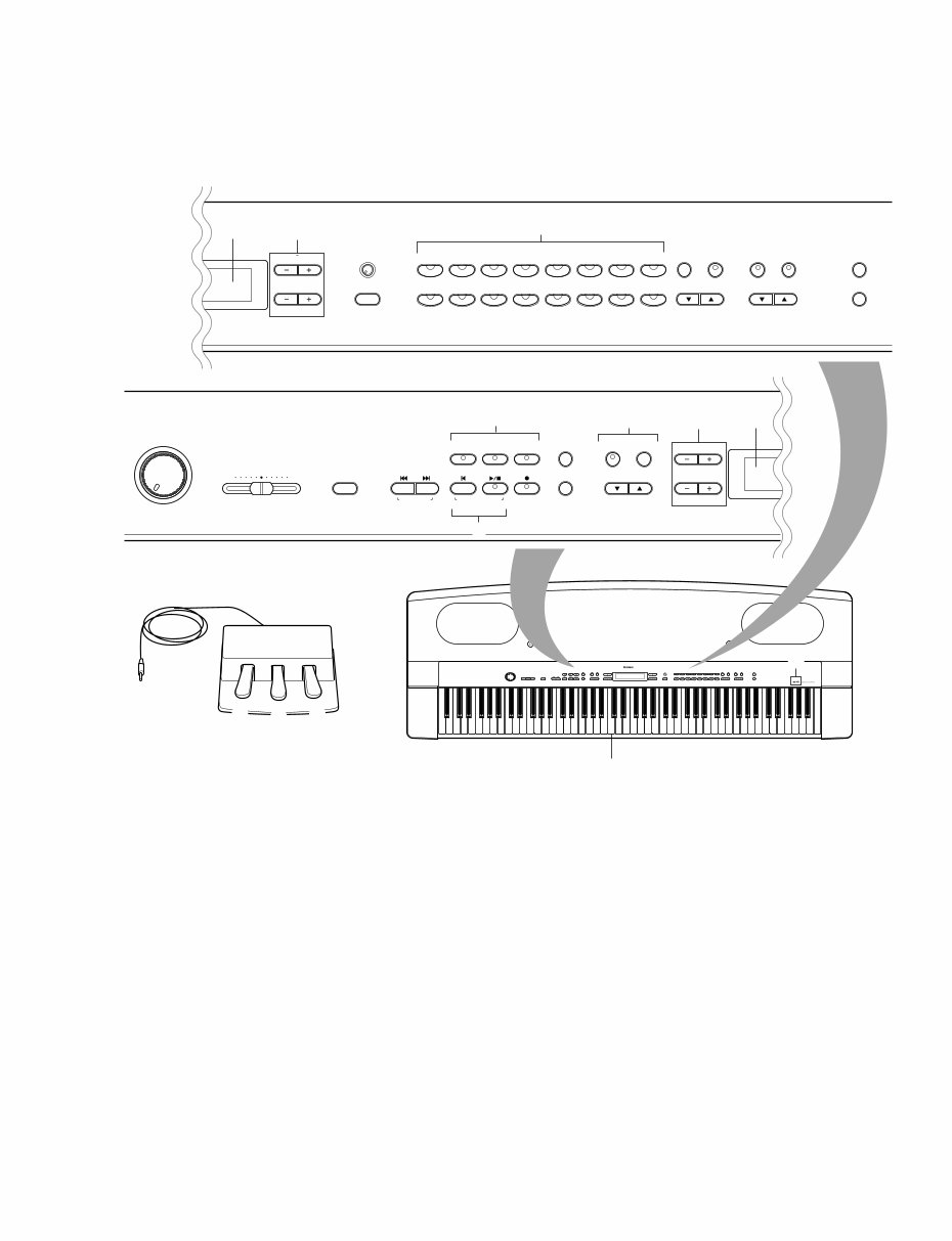
q [MASTER VOLUME] knob
w [SONG BALANCE] knob
e [DEMO] button
r SONG SELECT [ T ] [ Y ] buttons
t [TRACK1] [TRACK2] [EXTRA TRACKS] buttons
y [FILE] button
u SONG [TOP]/[START/STOP] buttons
i [REC] button
o [SONG SETTING] button
!0 METRONOME [START/STOP]/[SETTING] buttons
!1 TEMPO [DOWN] [UP] buttons
!2 LCD buttons
A [ – ] [ + ]/B [ – (NO)] [ + (YES)]/C [ – ] [ + ]/D [ – ] [ + ]
!3 LCD screen
!4 [CONTRAST] knob
■ PANEL LAYOUT
VARIATION BRIGHT MELLOW
BRILLIANCE
GRAND
PIANO 1
CHURCH
ORGAN
E.PIANO
1
STRINGS
E.PIANO
2
CHOIR
SPLIT CHORUS REVERB
GRAND
PIANO 2
JAZZ
ORGAN
HARPSI-
CHORD
SYNTH.
PAD
VIBRA-
PHONE
VOICE
SETTING
MIDI
SETTING
OTHER
SETTING
D
NO YES
B
E.BASS XG
GUITAR
E.CLAVI-
CHORD
WOOD
BASS
VOICE
EXIT
CONTRAST
EFFECT
DEMO TEMPO SONG BALANCE MASTER VOLUME
SONG KEYBOARD
SONG
SETTING
FILE
C
A
UP DOWN
TRACK
2
START/STOP SONG SELECT
NEW SONG
TRACK
1
TOP
SYNCHRO START
EXTRA
TRACKS
REC
SONG
MAX MIN
SETTING START/STOP
METRONOME
Center “C”
C0 D0 E0 F0 G0 A0 B0 C1 D1 E1 F1 G1 A1B1 C2 D2 E2 F2 G2 A2 B2 C3D3 E3 F3 G3 A3 B3C4 D4 E4 F4 G4 A4 B4 C5 D5 E5 F5 G5 A5 B5 C6 D6 E6 F6 G6 A6 B6 C7 B-1 A-1
!3 !2
!4
!5
!6
!7 !8
!9 @0
@1
@2
@3
@4
q w e
r
u
i
o
t
y
!0
!1
!2 !3
@5
@6
@7
#9
Top panel
q 【MASTER VOLUME】つまみ
w 【SONG BALANCE】つまみ
e 【DEMO】ボタン
r SONG SELECT 【T】 【Y】ボタン
t 【TRACK 】 【TRACK 】 【EXTRA TRACKS】ボタン
y 【FILE】ボタン
u SONG 【TOP】【STARTSTOP】ボタン
i 【REC】ボタン
o 【SONG SETTING】ボタン
!0 METRONOME 【STARTSTOP】【SETTING】ボタン
!1 TEMPO 【DOWN】 【UP】ボタン
!2 ボタン
A 【-】 【+】B 【-(NO)】 【+(YES)】C 【-】 【+】D
【-】 【+】
!3
!4 【CONTRAST】つまみ
(パネルレイアウト)
PF-500
6
!5 [EXIT] button
!6 Voice group buttons
!7 [VOICE SETTING] button
!8 [SPLIT] button
!9 [REVERB] button
@0 [CHORUS] button
@1 VARIATION [ G ] [ H ] buttons
@2 BRILLIANCE [MELLOW] [BRIGHT] buttons
@3 [MIDI SETTING] button
@4 [OTHER SETTING] button
@5 Soft pedal
@6 Sostenuto pedal
@7 Damper pedal
AUX PEDAL AC INLET
AUX IN
R L/L+R
MIDI
IN THRU OUT
PEDAL TO HOST USB HOST SELECT
MIDI PC-2 USB Mac
PHONES
ON OFF
POWER
R L R L/L+R
AUX OUT
LEVEL FIXED
@8
@9
#0 #1
#2 #3 #4
#5
#6 #7 #8
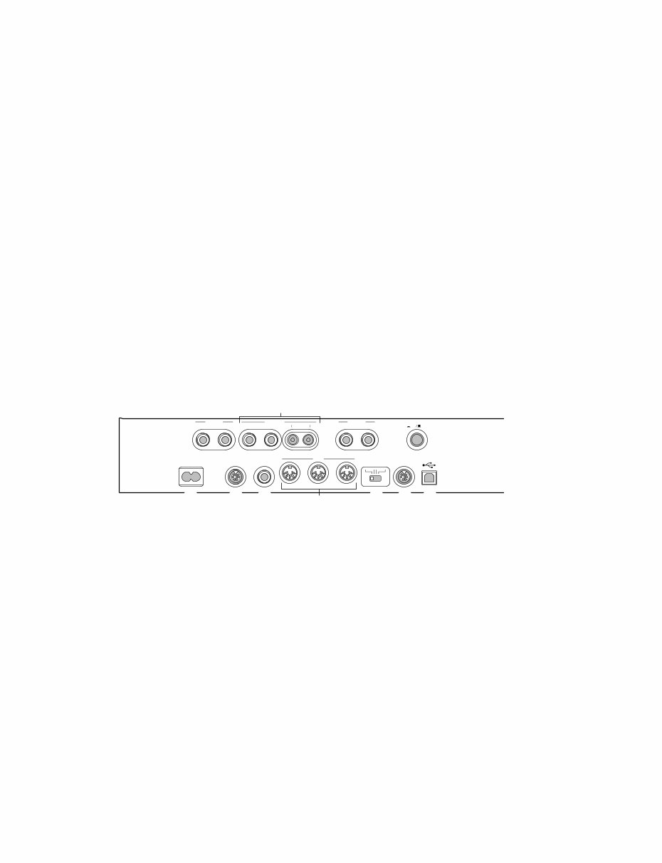
Connectors (Left side panel)
@8 AUX IN [L/L+R] [R] jacks
@9 AUX OUT [L/L+R] [R]/ (LEVEL FIXED) [L] [R] jacks
#0 [PHONES] jacks
#1 [POWER] switch
#2 [AC INLET] connector
#3 [PEDAL] connector
#4 [AUX PEDAL] jack
#5 MIDI [IN] [OUT] [THRU] connectors
#6 [HOST SELECT] switch
#7 [TO HOST] connector
#8 [USB] connector
!5 【EXIT】ボタン
!6 グループボタン
!7 【VOICE SETTING】ボタン
!8 【SPLIT】ボタン
!9 【REVERB】ボタン
@0 【CHORUS】ボタン
@1 VARIATION 【▼】 【▲】ボタン
@2 BRILLIANCE 【MELLOW】 【BRIGHT】ボタン
@3 【MIDI SETTING】ボタン
@4 【OTHER SETTING】ボタン
@5 ペダル(ソフトペダル)
@6 まん ペダル(ソステヌートペダル)
@7 右 ペダル(ダンパーペダル)
@8 AUX IN 【L L R】 【R】
@9 AUX OUT 【L L R】 【R】 LEVEL FIXED 【L】 【R】
#0 【PHONES】
#1 【POWER】スイッチ
#2 【AC INLET】
#3 【PEDAL】
#4 【AUX PEDAL】
#5 MIDI 【IN】 【OUT】 【THRU】
#6 【HOST SELECT】スイッチ
#7 【TO HOST】
#8 【USB】
端子パネル(左サイドパネル)
PF-500
7
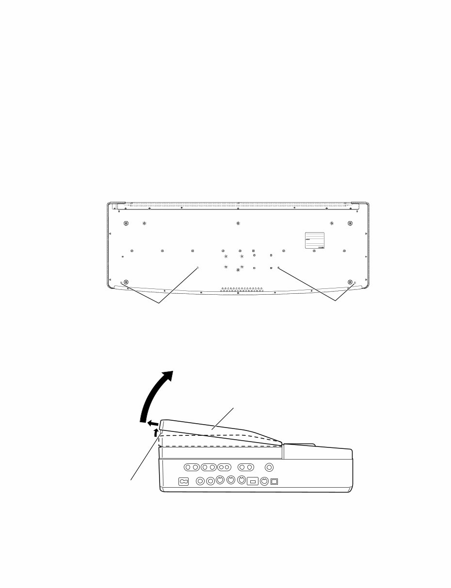
■ DISASSEMBLY PROCEDURE
(Fig. 1)
[180A]: Truss Head Screw 4.0x16 MFZN2BL (V6207400)
1. Top Board Assembly
(Time required : About 3 minutes)
1-1. Remove the music rest assembly.
1-2 Remove the four (4) screws marked [180A]. (Fig. 1)
1-3 Open the top board assembly. (Fig. 1-1)
(Fig. 1-1)
[180A]
[180A]
Bottom
Front
q
w
e
Top board assembly
Front
This unit can be disassembled whether the stand supplied as an
accessory is installed or not.
q Remove the boss by lifting the rear of the top board about
20mm.
w Move the top board rearward.
e Open the top board toward the front.
Boss
(分解手順)
1. 屋根Ass’y (所要時間:約3分)
を します。
[ A] ネジ を します。( )
Ass’yを けます。( )
+トラス小ネジ
q Ass’y を mm ち げて、ボスを します。
w Ass’yを ずらします。
e Ass’yを けます。
(図1)
(図1-1)
本機は、付属のスタンドの脱着と関係なく分解可能です。
(前)
(底面)
(屋根Ass’y)
(ボス)
(前)
PF-500
8
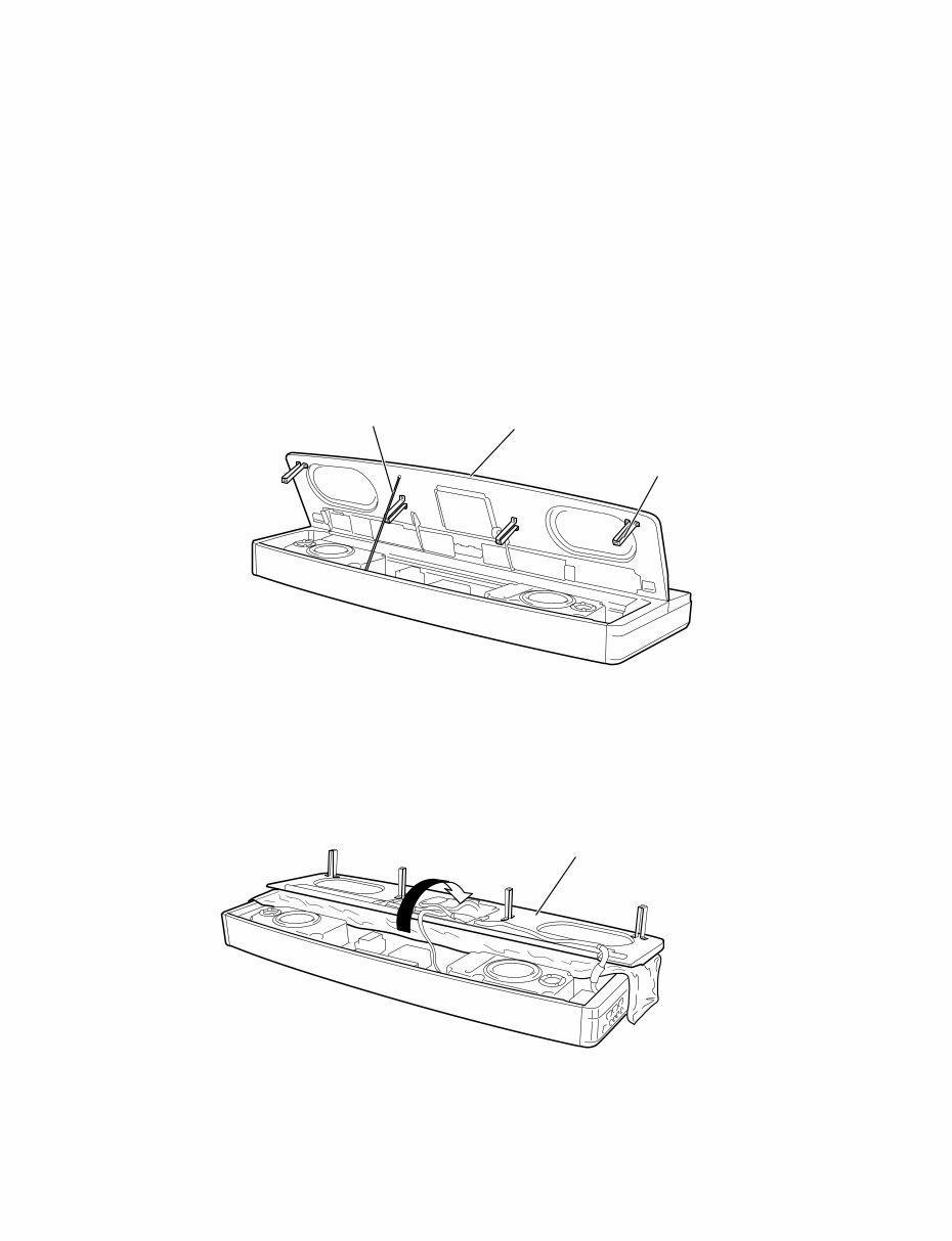
(Fig. 1-3)
(Fig. 1-2)
Top board assembly
Top board assembly
Stay
U-shaped holder
1-4 Remove the stay existing inside of the rear panel and set
it up. (Fig. 1-2)
1-5 Spread a soft cloth or the like over the keyboard in advance
so that the top board assembly can be placed on it.
1-6 Release the stay while holding the U-shaped holder of
the top board assembly. (Fig. 1-2)
1-7 Gradually turn over the top board assembly until it lies
on the cloth spread over the keyboard. (Fig. 1-3)
に り けられている ステーを して、
します。( )
Ass’yを に くためにあらかじめ らかい
を いておきます。
Ass’ y U (A)を って、ステーを します。
( )
Ass’yをゆっくり して きます。
( )
(図1-2)
(図1-3)
(屋根Ass’y)
(屋根Ass’y)
(ステー)
(U字金具(A))
PF-500
9
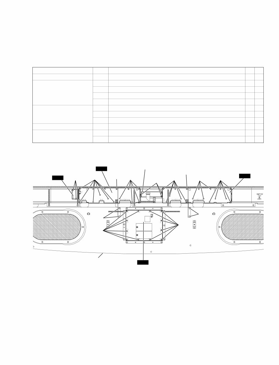
Circuit board and Assembly Ref. No. Screw QTY Fig.
DM 170A Bind Head Tapping Screw-B 3.0x6 MFZN2Y (EP600130) 12 2
PNL Slide Knob 1
180B Bind Head Tapping Screw-1 3.5x12 MFZN2Y (EP030240) 2 2
190A Bind Head Tapping Screw-B 3.0x8 MFZN2Y (EP600250) 1 2
P270A Bind Head Tapping Screw-B 3.0x8 MFZN2Y (EP600250) 13 2
PNR 180C Bind Head Tapping Screw-1 3.5x12 MFZN2Y (EP030240) 2 2
190B Bind Head Tapping Screw-B 3.0x8 MFZN2Y (EP600250) 1 2
P270B Bind Head Tapping Screw-B 3.0x8 MFZN2Y (EP600250) 16 2
LCD Assembly P270C Bind Head Tapping Screw-B 3.0x8 MFZN2Y (EP600250) 3 2
MV2 Knob 1
P270D Bind Head Tapping Screw-B 3.0x8 MFZN2Y (EP600250) 3 2
2. Circuit Boards & Assemblies (Top Board Assembly)
(Time required : About 7 minutes each)
2-1 Turn over the top board assembly toward the front.
(See procedure 1)
2-2 Each circuit board and assembly can be removed by
removing its fixing screws as listed below.
(Fig. 2)
[P270D] [P270A]
[190A]
[P270A]
[P270C]
[P270B]
[190B]
[P270B] [P270B]
[180C]
[180B]
[170A]
[170A]
MV2
PNL
PNR
DM
LCD assembly
Top board assembly
(屋根Ass’y)
2. 基板、アッセンブリ(屋根Ass’y部)
(所要時間:各約7分)
Ass’ yを します。 ( )
ネジを すこ により、各 ・アッセンブリを
すこ が きます。
+バインドBタイト
スライドツマミ
+バインドTP1種
+バインドBタイト
+バインドBタイト
+バインドTP1種
+バインドBタイト
+バインドBタイト
+バインドBタイト
Vツマミ
+バインドBタイト
(図2)
PF-500
10
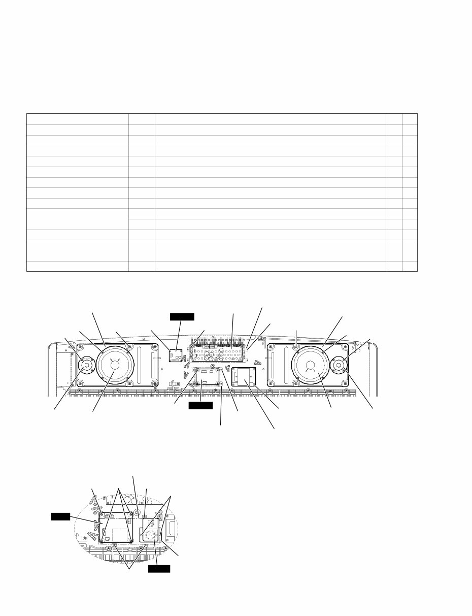
Circuit board and Assembly Ref. No. Screw QTY Fig.
Speaker Box Assembly (L/R) 120 Truss Head Tapping Screw-1 3.5x16 MFZN2Y (EN630030) 6 3
Speaker (Woofer) 130A Bind Head Tapping Screw-B 4.0x12 MFZN2BL (VR138400) 4 3
Speaker (Tweeter) 130B Bind Head Tapping Screw-B 4.0x12 MFZN2BL (VR138400) 4 3
NET1 170B Bind Head Tapping Screw-1 3.5x20 MFZN2Y (EP030470) 4 3
MA Cover (U model only) 350A Bind Head Tapping Screw-1 3.5x12 MFZN2Y (EP030240) 4 3
MA60 Assembly 350B Bind Head Tapping Screw-1 3.5x12 MFZN2Y (EP030240) 4 3
FU Cover (U model only) 350C Bind Head Tapping Screw-1 3.5x12 MFZN2Y (EP030240) 4 3
FU60P (Except N model) 230A Bind Head Screw 3.0x8 MFZN2Y (VD976600) 4 3
Cover (N model only) 230B Bind Head Screw 3.0x8 MFZN2Y (VD976600) 1 3
350D Bind Head Tapping Screw-1 3.5x12 MFZN2Y (EP030240) 3 3
FU (N model only) 230C Bind Head Screw 3.0x8 MFZN2Y (VD976600) 3 3
VSEL Plate Assembly
350E Bind Head Tapping Screw-1 3.5x12 MFZN2Y (EP030240) 2 3
(N model only)
Power Transformer 210 Bind Head Screw 4.0x12 MFZN2Y (EG340030) 4 3
3. Circuit Boards & Assemblies (Main Unit)
(Time required : About 6 minutes each)
3-1 Open the top board assembly. (See procedure 1-1 to 1-4)
3-2 Each circuit board and assembly can be removed by
removing its fixing screws as listed below.
NET1
FU60P
[130B] x 4
[130A] x 4 [120] x 6
[170B] x 4
[350B] x 4
[210] x 4
[230] x 4
[350C] x 4
[130B] x 4
[130A] x 4
[120] x 6
[350A] x 4
[230C]
[350E]
FU
[230B]
[350D]
[350D]
VSEL
(Fig. 3)
Power transformer
MA60 assembly
MA cover
Woofer
Tweeter
Woofer
Tweeter
FU cover
Speaker box assembly L
Speaker box assembly R
N model
VSEL plate assembly
Cover
3. 基板、アッセンブリ(メインユニット部)
(所要時間:各約6分)
Ass’ yを けます。 ( ~ )
ネジを すこ により、各 ・アッセンブリを
すこ が きます。
+トラスTP1種
+バインドBタイト
+バインドBタイト
+バインドTP1種
+バインドTP1種
+バインドTP1種
+バインドTP1種
+バインド小ネジ
+バインド小ネジ
+バインドTP1種
+バインド小ネジ
+バインドTP1種
+バインド小ネジ
(図3)
(電源トランス)
(MA60 Ass’ y)
(SP Box Ass’y R)
(SP Box Ass’y L)
(ツィータ)
(ウーハー)
(ウーハー)
(ツィータ)
(ウーハー)
(ツィータ)
(電源トランス)
You're Reading a Preview
What's Included?
Fast Download Speeds
Online & Offline Access
Access PDF Contents & Bookmarks
Full Search Facility
Print one or all pages of your manual
$33.99
YAMAHA PF-500 ELECTRONIC PIANO Service Manual
Viewed 43 Times Today

What's Included?
Fast Download Speeds
Online & Offline Access
Access PDF Contents & Bookmarks
Full Search Facility
Print one or all pages of your manual
$33.99

Secure transaction
What's Included?
Fast Download Speeds
Online & Offline Access
Access PDF Contents & Bookmarks
Full Search Facility
Print one or all pages of your manual
Description
The YAMAHA PF-500 ELECTRONIC PIANO Service Manual is a comprehensive guide for professionals and DIY enthusiasts alike. This manual, available in English, provides detailed technical information essential for the repair and maintenance of the YAMAHA PF-500 ELECTRONIC PIANO. Whether you are a professional technician or a passionate DIYer, this manual equips you with the necessary knowledge to effectively service the electronic piano.


