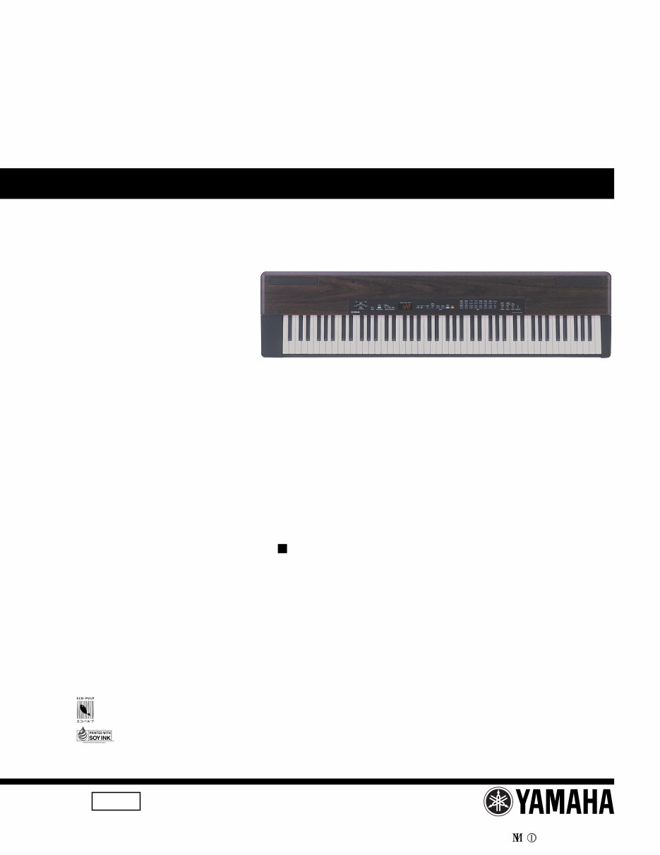
Yamaha P-120 + P-120S Electronic Piano Service Manual & Repair Guide
What's Included?
Lifetime Access
Fast Download Speeds
Online & Offline Access
Access PDF Contents & Bookmarks
Full Search Facility
Print one or all pages of your manual
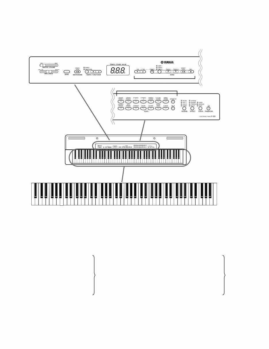
SERVICE MANUAL HAMAMATSU, JAPAN 1.702K-5011 Printed in Japan ’01, 09 PK 000344 CONTENTS (目次) SPECIFICATIONS(総合仕様) ........................................................... 3 PANEL LAYOUT(パネルレイアウト) ............................................... 4 CIRCUIT BOARD LAYOUT(ユニットレイアウト) ........................... 6 DISASSEMBLY PROCEDURE(分解手順) ....................................... 7 LSI PIN DESCRIPTION(LSI 端子機能表) ....................................... 15 IC BLOCK DIAGRAM (IC ブロック図) ........................................... 16 CIRCUIT BOARDS(シート基板図) ................................................ 18 TEST PROGRAM(テストプログラム) ........................................... 26 MIDI IMPLEMENTATION CHART ..................................................... 36 PARTS LIST BLOCK DIAGRAM(ブロックダイアグラム) OVERALL CIRCUIT DIAGRAM(総回路図) P-120 20011015-160000 P-120S L-120 20011015-9000 L-120S ELECTRONIC PIANO P-120/P-120S This document is printed on chlorine free (ECF) paper with soy ink. このサービスマニュアルはエコパルプ� (ECF: 無塩素系漂白パルプ)を使用しています。� このサービスマニュアルは� 大豆油インクで印刷しています。� � • OPTION (別売品) 別売品) 別売品) 別売品) 別売品) L-120/L-120S KEYBOARD STAND キーボードスタンド P120
2 P-120/P-120S IMPORTANT NOTICE This manual has been provided for the use of authorized Yamaha Retailers and their service personnel. It has been assumed that basic service procedures inherent to the industry, and more specifically Yamaha Products, are already known and understood by the users, and have therefore not been restated. WARNING: Failure to follow appropriate service and safety procedures when servicing this product may result in per- sonal injury, destruction of expensive components and failure of the product to perform as specified. For these reasons, we advise all Yamaha product owners that all service required should be performed by an authorized Yamaha Retailer or the appointed service representative. IMPORTANT: This presentation or sale of this manual to any individual or firm does not constitute authorization, certifica- tion, recognition of any applicable technical capabilities, or establish a principal-agent relationship of any form. The data provided is believed to be accurate and applicable to the unit(s) indicated on the cover. The research engineering, and service departments of Yamaha are continually striving to improve Yamaha products. Modifications are, therefor, inevitable and changes in specification are subject to change without notice or obligation to retrofit. Should any discrepancy appear to exist, please contact the distributor's Service Division. WARNING: Static discharges can destroy expensive components. Discharge any static electricity your body may have accumulated by grounding yourself to the ground bus in the unit (heavy gauge black wires connect to this bus). IMPORTANT: Turn the unit OFF during disassembly and parts replacement. Recheck all work before you apply power to the unit. WARNING: CHEMICAL CONTENT NOTICE! The solder used in the production of this product contains LEAD. In addition, other electrical / electronic and / or plastic (where applicable) components may also contain traces of chemicals found by the California Health and Welfare Agency (and possibly other entities) to cause cancer and / or birth defects or other reproductive harm. DO NOT PLACE SOLDER, ELECTRICAL / ELECTRONIC OR PLASTIC COMPONENTS IN YOUR MOUTH FOR ANY REASON WHAT SO EVER! Avoid prolonged, unprotected contact between solder and your skin! When soldering, do not inhale solder fumes or expose eyes to solder / flux vapor! If you come in contact with solder or components located inside the enclosure of this product, wash your hands before handling food. IMPORTANT NOTICE FOR THE UNITED KINGDOM Connecting the Plug and Cord WARNING: THIS APPARATUS MUST BE EARTHED IMPORTANT: The wires in this main lead are coloured in accor- dance with the following code: GREEN-AND-YELLOW: EARTH BLUE: NEUTRAL BROWN: LIVE As the colours of the wires in the main lead of this apparatus may not correspond with the coloured markings identifying the terminals in your plug, proceed as follows: The GREEN-and-YELLOW wire must be connected to the terminal in the plug that is marked with the letter E or the safety earth symbol (or coloured GREEN or GREEN-and-YELLOW). The BLUE wire must be connected to the terminal that is marked with the letter N (or coloured BLACK). The BROWN wire must be connected to the terminal that is marked with the letter L (or coloured RED). This applies only to products distributed by Yamaha Kemble Music (U. K.) Ltd. ■ WARNING Components having special characteristics are marked and must be replaced with parts having specification equal to those originally installed. 印 、安 を維 するために す。 する 、安 ため ず をご さい。
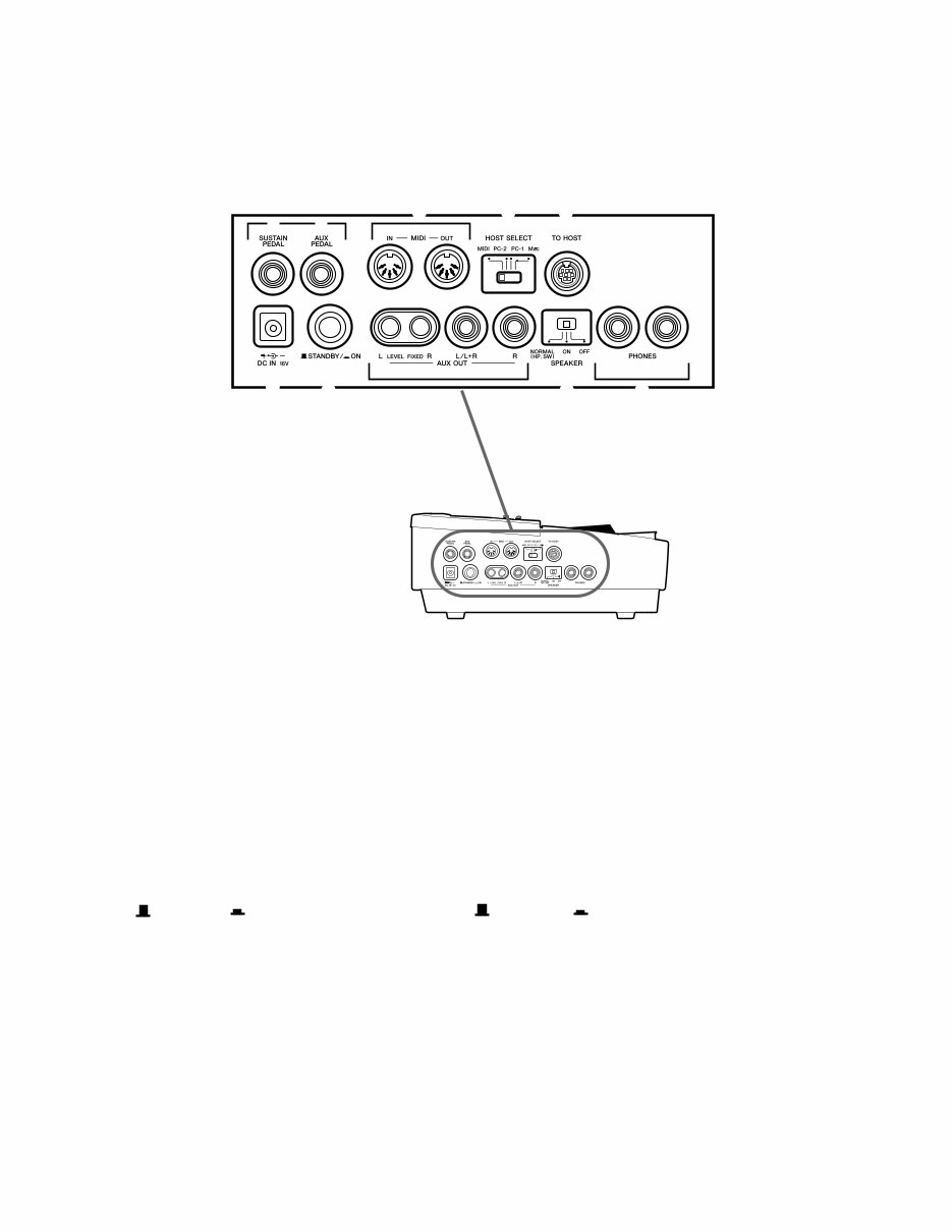
3 P-120/P-120S ■ SPECIFICATIONS (総合仕様) KEYBOARD 88 (A-1 ~ C7) POLYPHONY 64 NOTES MAX VOICE SELECTORS 14 Voices + Variation for each voice REVERB ROOM, HALL1, HALL2, STAGE EFFECT CHORUS, PHASER, TREMOLO, DELAY TOUCH SENSITIVE HARD, MEDIUM, SOFT, FIXED SONG CONTROLS PRESET, USER 1/2/3, TRACK 1/2, START/STOP, REC PEDAL CONTROLS SUSTAIN (HALF PEDAL SUPPORT), AUX PEDAL OTHER CONTROLS MASTER VOLUME, BRILLIANCE, DEMO, METRONOME START/STOP, TEMPO/FUNCTION # ▲/▼, -/NO ▼, +/YES ▲, SPLIT, TRANSPOSE, LED Display JACK/CONNECTORS AUX OUT (LEVEL FIXED) L/R, AUX OUT L/L+R, SUSTAIN PEDAL, AUX PEDAL, PHONES x 2, TO HOST, MIDI IN/OUT, DC IN 12V OUTPUT IMPEDANCE 600Ω MAIN AMPLIFIER 12.5W x 2 SPEAKER OVAL (12cm x 6cm) x 2 POWER SUPPLY AC ADAPTER PA-300 POWER CONSUMPTION 26W DIMENSIONS (WxDxH) 1354 x 334 x 137 mm (53-1/4" x 13" x 5-1/2") WEIGHT 18.6 kg (41 lbs.) 鍵盤 88鍵(A-1~C7) 音源 AWMダイナミックスステレオサンプリング 最大同時発音数 最大64音 音色数 14+各音色バリエーション 効果 ブリリアンス、リバーブ(ルーム/ホール1/ホール2/ステージ)、エフェクト (コーラス/フェーザー/トレモロ/ディレイ) ボリューム マスターボリューム コントロール デュアル、スプリット、メトロノーム、トランスポーズ、タッチ(ハード/ミ ディアム/ソフト/フィックス)、各種ファンクション、スピーカーON/OFF レコーダー 2トラック録音/再生(3曲)、テンポ、シンクロスタート ペダル サステイン(ハーフペダル対応)、多機能割り当て デモ 各音色デモ曲、ピアノ曲50曲 付属端子 AUX OUT (LEVEL FIXED)(L,R)端子、AUX OUT(L/L+R,R)端子、SUSTAIN PEDAL端子、AUX PEDAL端子、PHONES(ヘッドフォン)端子×2、TO HOST 端子、MIDI端子(IN、OUT) 出力インピーダンス 600Ω メインアンプ 12.5W×2 スピーカー 楕円(12cm×6cm)×2 定格電源 電源アダプターPA-300 消費電力 26W 寸法[間口×奥行き×高さ] 1354mm×334mm×137mm 質量 18.6kg 付属品 電源アダプターPA-300、ペダル、譜面立て、取扱説明書、ピアノで弾く名曲50 選(楽譜集)、保証書
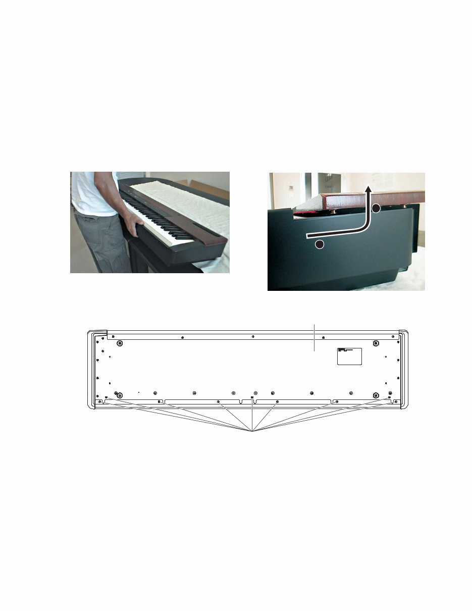
7 P-120/P-120S ■ DISASSEMBLY PROCEDURE (分解手順) * Lay the soft cloth under the unit to protect it from being scratched. 1. Top Board Assembly (Time required: about 2min) * Apply a masking tape to the edge of the top board assembly to protect it from being scratched. 1-1 Turn the unit backward to get up and remove the nine (9) screws marked [280]. (Fig.1, Fig.2) 1-2 Lay down the unit again, slide the top board assembly backward until it stops, and lift it out. (Fig.3) (Fig.1) [280] Keybed Assembly Bottom Side 1 2 を う き 、 体に がつく を ぐた め、 わらかい を いてください。 1. 屋根Ass'y( 所要時間:約2分) Ass y ふちにマスキングテープ を り、 がつく を してください。 体 フロント を ち げて こし、[ ] ネジ を ずします。 Fig Fig 体を に し、 Ass yを に まるま ずらし、 ち げて します。 Fig (Fig.2) (Fig.3) [280]: Bind Head Screw 4.0X16 MFZN2BL (EG340110) +バインド小ネジ
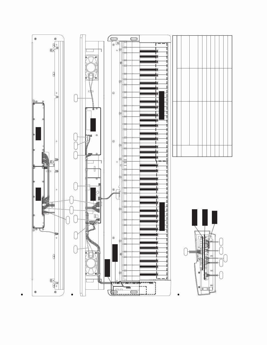
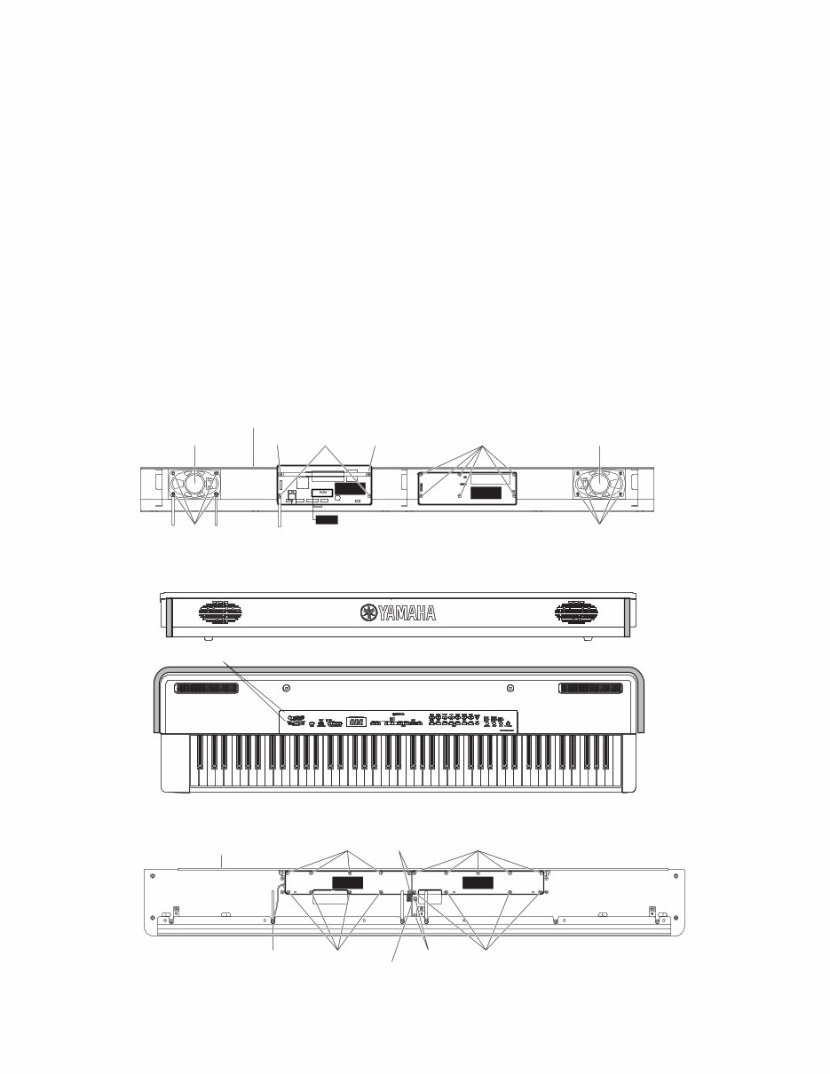
8 P-120/P-120S 2. DM Circuit Board (Time required: about 3min) 2-1 Remove the top board assembly. (See procedure.1) 2-2 Remove the two (2) screws marked [290a] and the two (2) screws marked [320]. The DM circuit board can then be removed. (Fig.4) * When reinstalling the top board assembly, apply a masking tape to the shaded portion in the illustra- tion to protect the side cover assembly from being scratched. (Fig.5) 3. AMP Circuit Board (Time required: about 3min) 3-1 Remove the top board assembly. (See procedure.1) 3-2 Remove the six (6) screws marked [290b]. The AMP circuit board can then be removed. (Fig.4) 4. PNR Circuit Board (Time required: about 3min) 4-1 Remove the top board assembly. (See procedure.1) 4-2 Remove the nine (9) screws marked [130a]. The PNR circuit board can then be removed. (Fig.6) 2. DMシート(所要時間:約3分) Ass yを します。 [ a] ネジ [ ] ネジ を し、DM シートを します。 Fig Ass yを り ける き、 Ass yに が つく を ぐため、 掛け にマスキ ングテープを ってください。 Fig 3. AMPシート(所要時間:約3分) Ass yを します。 [ b] ネジ を し、AMPシートを しま す。 Fig 4. PNRシート(所要時間:約3分) Ass yを します。 [ a] ネジ を し、PNRシートを します。 Fig PNL PNR Panel Angle [240a] [300] [130a] [130b] [130a] [130b] [240b] Top Board Assembly (Bottom veiw) (Fig.6) [130]: Bind Head Tapping Screw-B 3.0X8 MFZN2Y (EP600250) +バインドBタイト [240]: Bind Head Tapping Screw-1 3.5X12 MFZN2BL (EP030340) +バインドTP1種 [300]: Bind Head Tapping Screw-B 3.0X10 MFZN2BL (EP600140) +バインドBタイト Speaker L Top Board Assembly [290a] [320] [320] [290b] [30d] [30d] Speaker R AMP DM ROM (C Version Only) (Fig.4) [30d]: Hexagonal Nut MFZN2Y (03760120) 六角ナット [290]: Bind Head Tapping Screw-B 3.0X6 MFZN2Y (EP600130) +バインドBタイト [320]: Bind Head Screw-B 3.0X8 MFZN2BL (EP600190)+バインドBタイト [80] [80]: Slide Knob (V8085100) ツマミ (スライド) (Fig.5)
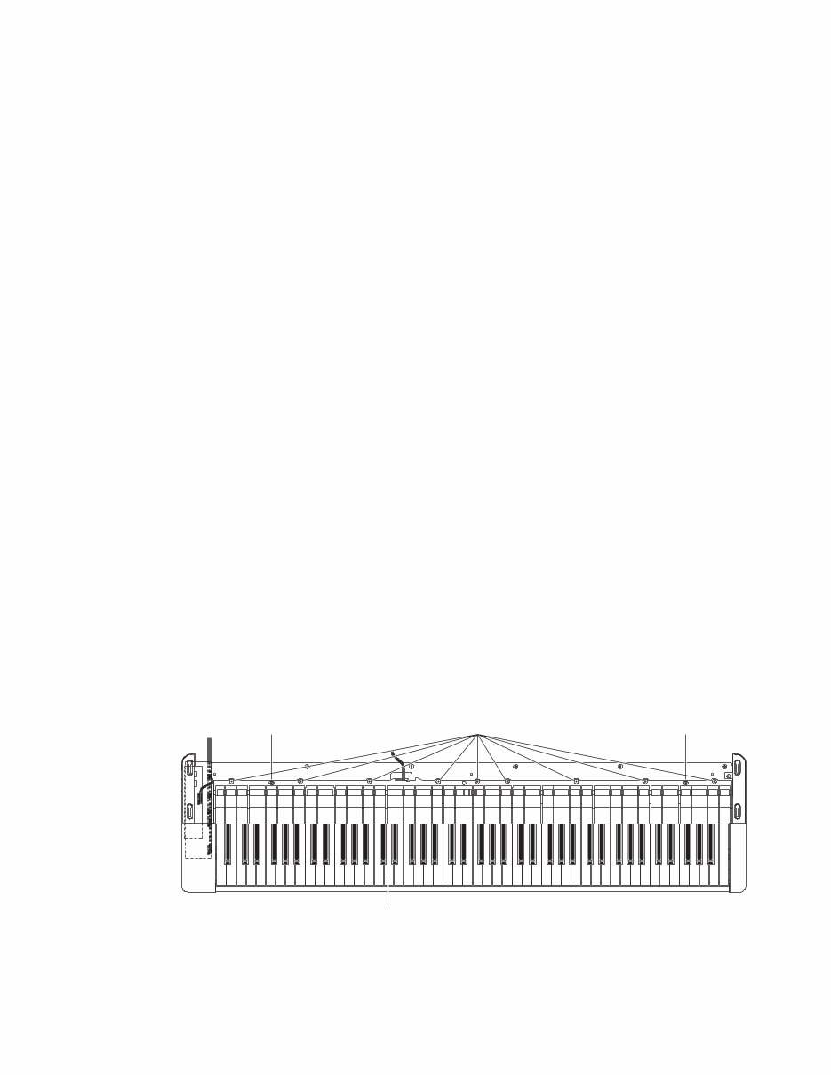
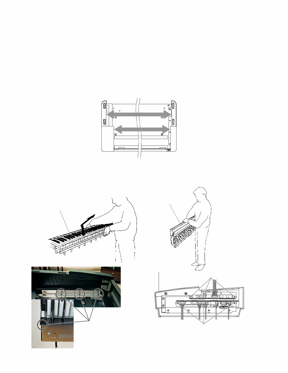
9 P-120/P-120S 5. PNL Circuit Board (Time required: about 3min) 5-1 Remove the two (2) slide knobs marked [80]. (Fig.5) 5-2 Remove the top board assembly. (See procedure.1) 5-3 Remove the two (2) screws marked [240a] and two (2) screws marked [300]. The panel angle assembly can then be removed. (Fig.6) 5-4 Remove the eight (8) screws marked [130b] and the screw marked [240b]. The PNL circuit board can then be removed. (Fig.6) 6. Speakers (Time required: about 3min) 6-1 Remove the top board assembly. (See procedure.1) 6-2 Remove the four (4) hexagonal nuts marked [30d]. The speaker can then be removed. (Fig.4) * Both of the right and the left speaker can be removed by the same procedure. 7. Keyboard Assembly (Time required: about 4min) 7-1 Remove the top board assembly. (See procedure.1) 7-2 Remove the two (2) screws marked [250] and the nine (9) screws marked [260]. The keyboard assembly can then be removed. (Fig.7) * Hold the central area of the frame to prevent it from twisting and turn the keyboard assembly forward to get up. (Fig.9) * When moving the keyboard assembly, the screws marked [230] which fix the side cover assembly may stand in the way. (Fig.10) Then lift the keyboard assembly fitly to avoid those screws. * To remove the keyboard assembly easily, slide it rearward, over the center of the side cover, to the area hiding under the top board assembly. (Fig.8) 5. PNLシート(所要時間:約3分) [ ] スライドツマミ を します。 Fig Ass yを します。 [ a] ネジ 、[ ] ネジ を し、パ ネル を します。 Fig [ b] ネジ [ b] ネジを し、PNL シートを します。 Fig 6. スピーカ(所要時間:約3分) Ass yを します。 [ d] 角ナット を し、スピーカを し ます。 Fig 右 スピーカ 、 じ すこ が きます。 7. GHDcl鍵盤Ass'y( 所要時間:約4分) Ass yを します。 [ ] ネジ [ ] ネジ を し、 か ら Ass yを します。 Fig GHDcl Ass yを す き 、 ユニットが じれ いようにフレーム 央を ち げ、 ユニットを に こします。 Fig り しおよび り け き、 Ass y を している[ ] ネジがフレームに引っか かります。 Fig そ に じて Ass yを ち げ、 に かします。 Ass y 右 より いため、 に ずらさ い すこ が きません。 Fig 央より Ass yに隠れている ま ずらすこ により、 り しが 易に ります。 GHD Keyboard Assembly [250] [250] [260] (Fig.7) [250]: Bind Head Tapping Screw-1 4.0X14 MFZN2Y (EP040230) +バインドTP1種 [260]: Pan Head Screw 5.0X25 MFZN2Y PW (VV040700) +ナベ小ネジ
10 P-120/P-120S 8. DJACK Circuit Board (Time required: about 5min) 8-1 Remove the top board assembly. (See procedure.1) 8-2 Remove the keyboard assembly. (See procedure.7) 8-3 Remove the four (4) screws marked [230a] and the screw marked [360] from the bottom of the unit. The side cover assembly L can then be removed. (Fig.11) 8-4 Remove the three (3) screws marked [240a]. The DJACK circuit board can then be removed. (Fig.12) 8. DJACKシート( 所要時間:約5分) Ass yを します。 Ass yを します。 体 より[ a] ネジ [ ] ネジ を し、 Ass y Lを します。 Fig [ a] ネジ を し、DJACKシートを します。 Fig Keyboard assembly (� GHD鍵盤� Ass’y)� Keyboard assembly (� GHD鍵盤� Ass’y)� (Fig.9) Keyboard Bottom side Keyboard Bottom side Side Cover Assembly Side Cover Assembly 干渉部分� (Fig.10) [240a] [240b] Side Cover Assembly (L) (Fig.12) [240]: Bind Head Tapping Screw-B 3.0X8 MFZN2Y (EP600250) +バインドBタイト (Fig.8)
Are you experiencing issues with your Yamaha P-120/P120S Electronic Piano? Why spend a fortune on repairs or replacements when you can easily handle it yourself? This comprehensive service and repair manual is utilized by the Official Certified Yamaha Technicians and is designed to assist you in troubleshooting and fixing your piano.
The manual includes detailed specifications, panel layout, circuit board layout, disassembly procedure, LSI pin description, IC block diagram, circuit boards, test program, MIDI implementation chart, parts list, block diagram, and overall circuit diagram. Each section is accompanied by step-by-step instructions and high-resolution images to ensure you can effectively service and repair your device.
Upon purchase, you will gain instant access to the manual without any shipping fees or delays. The manual is available in English and is compatible with both Windows and MAC platforms. With 62 pages of valuable information, this manual is an indispensable resource for professional mechanics and DIY enthusiasts alike.
If you are unable to find a specific service manual, feel free to reach out to us with your request. With one of the largest service manual databases, we are well-equipped to assist you in your repair endeavors.
Recently Viewed
5,521,897Happy Clients
2,594,462eManuals
1,120,453Trusted Sellers
15Years in Business
Price:
Actual Price:
Yamaha P-120 + P-120S Electronic Piano Service Manual & Repair Guide