Yamaha Modus F01 Series Piano Service Manual & Repair Guide
What's Included?
Lifetime Access
Fast Download Speeds
Online & Offline Access
Access PDF Contents & Bookmarks
Full Search Facility
Print one or all pages of your manual
SERVICE MANUAL HAMAMATSU, JAPAN Copyright (c) Yamaha Corporation. All rights reserved. ’08.01 CL 001798 CONTENTS(目次) SPECIFICATIONS(総合仕様) ................................................ 3 PANEL LAYOUT(パネルレイアウト) .................................... 4 DISASSEMBLY PROCEDURE(分解手順) ............................ 6 LSI PIN DESCRIPTION(LSI 端子機能表) ............................ 24 IC BLOCK DIAGRAM (IC ブロック図) ............................... 27 CIRCUIT BOARDS(シート基板図) ..................................... 29 TEST PROGRAM(テストプログラム) ............................ 45/50 DATA BACKUP(ユーザーデータのバックアップ) ........... 55/59 VERSION UPGRADE(バージョンアップ) ...................... 56/60 SYSTEM BOOTING FLOW CHART (システム起動フローチャート) ..................................... 63/64 MIDI IMPLEMENTATION CHART (MIDI インプリメンテーションチャート) ............................ 65 MIDI DATA FORMAT ............................................................... 66 PARTS LIST BLOCK DIAGRAM(ブロックダイアグラム) CIRCUIT BOARD LAYOUT & WIRING (ユニットレイアウト及び結線図) OVERALL CIRCUIT DIAGRAM(総回路図) F01PE F01PO F01PB F01PR F01PE: 20071101-483000 F01PO:20071101-483000 F01PB: 20071101-483000 F01PR: 20071101-483000 PN-MF01PE: 20071101-94500 PN-MF01PO: 20071101-94500 PN-MF01PB: 20071101-94500 PN-MF01PR: 20071101-94500 BC-103PE: 20071101-42000
2 F01 Saving and backing up your data SAVING DATA Be sure to perform it IMPORTANT NOTICE This manual has been provided for the use of authorized Yamaha Retailers and their service personnel. It has been assumed that basic service procedures inherent to the industry, and more specifically Yamaha Products, are already known and understood by the users, and have therefore not been restated. WARNING: Failure to follow appropriate service and safety procedures when servicing this product may result in per- sonal injury, destruction of expensive components and failure of the product to perform as specified. For these reasons, we advise all Yamaha product owners that all service required should be performed by an authorized Yamaha Retailer or the appointed service representative. IMPORTANT: This presentation or sale of this manual to any individual or firm does not constitute authorization certifi- cation, recognition of any applicable technical capabilities, or establish a principal-agent relationship of any form. The data provided is believed to be accurate and applicable to the unit(s) indicated on the cover. The research engineering, and service departments of Yamaha are continually striving to improve Yamaha products. Modifications are, therefore, inevitable and changes in specification are subject to change without notice or obligation to retrofit. Should any discrepancy appear to exist, please contact the distributor's Service Division. WARNING: Static discharges can destroy expensive components. Discharge any static electricity your body may have accumulated by grounding yourself to the ground bus in the unit (heavy gauge black wires connect to this bus.) IMPORTANT: Turn the unit OFF during disassembly and parts replacement. Recheck all work before you apply power to the unit. Components having special characteristics are marked and must be replaced with parts having specification equal to those originally installed. WARNING IMPORTANT NOTICE FOR THE UNITED KINGDOM Connecting the Plug and Cord IMPORTANT: The wires in this mains lead are coloured in accordance with the following code: BLUE : NEUTRAL BROWN : LIVE As the colours of the wires in the mains lead of this apparatus may not correspond with the coloured makings identifying the terminals in your plug proceed as follows: The wire which is coloured BLUE must be connected to the terminal which is marked with the letter N or coloured BLACK. The wire which is coloured BROWN must be connected to the terminal which is marked with the letter L or coloured RED. Making sure that neither core is connected to the earth terminal of the three pin plug. • This applies only products distributed by Yamaha-Kemble music (U.K.) Ltd. (2 wires) Some data will be saved to the internal memory of the instrument. The data is maintained even when the power is turned off. For maximum data security, save important data to a USB storage device/or other external device such as a computer. This provides a convenient backup if the internal memory is damaged. 印の商品は、安全を維持するために重要な部品です。交換する場合は、安全のために必ず指定の部品をご使用ください。� 一部のデータは、本体内部のメモリーに保存されます。電源を切っても消えずに残ります。本体 に保存されたデータの万一の事故に備えて、大切なデータはバックアップとしてUSBメモリ、ま たはコンピューターに保存して下さい。� (作成したデータの保存とバックアップ)� WARNING: This product contains chemicals known to the State of California to cause cancer, or birth defects or other reproductive harm. DO NOT PLACE SOLDER, ELECTRICAL/ELECTRONIC OR PLASTIC COMPONENTS IN YOUR MOUTH FOR ANY REASON WHAT SO EVER! Avoid prolonged, unprotected contact between solder and your skin! When soldering, do not inhale solder fumes or expose eyes to solder/ flux vapor! If you come in contact with solder or components located inside the enclosure of this product, wash your hands before handling food.
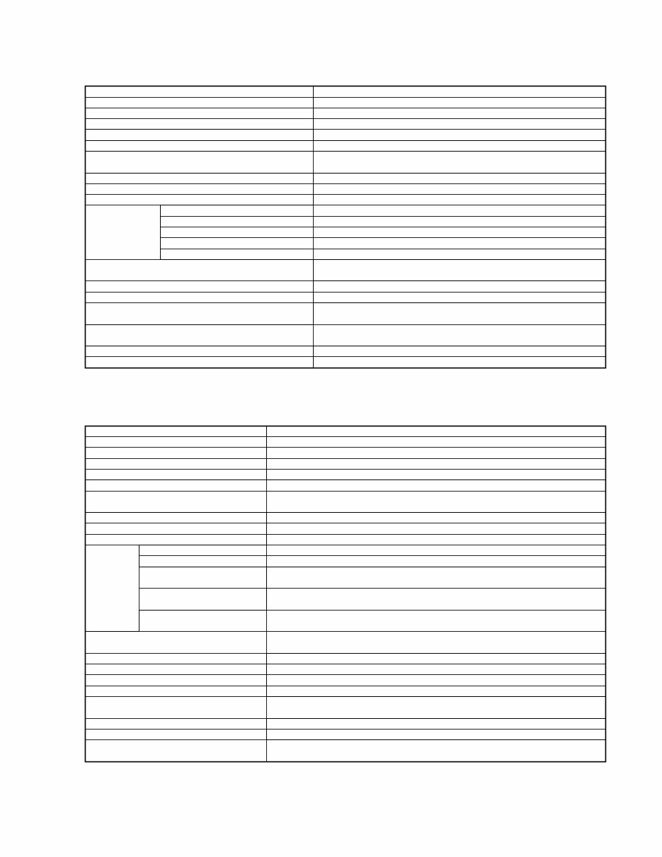
3 F01 Keyboard NW (Natural Wood) Keyboard (Wood is used for the white keys) Number of keys 88 Sound Source AWM Dynamic Stereo Sampling Polyphony (max.) 64 Voice Selection 10 x 2 variations Effect Reverb Controls Dual, Split, Metoronome, Transpose, Touch (Hard/Medium/Soft/Fixed), Tuning Recording/Playback 1 user song; can be saved to USB device Pedal Damper (apply a half pedal), Sostenuto, Soft Voice Demo Songs 50 Piano Preset Songs (Classic & Jazz), 10 voice Demo Songs Memory Device Flash Memory (Internal) about 512KB USB Flash Memory YES (via USB [TO DEVICE]) Floppy Disk (2HD, 2DD) External Adaptor (via USB [TO DEVICE]) Hard Disk External Adaptor (via USB [TO DEVICE]) Memory Card (SmartMedia, etc.) External Adaptor (via USB [TO DEVICE]) Connectors [PHONES] x 2, AUX OUT[L/L+R][R] jacks, AUX IN [L/L+R][R] jacks, MIDI [IN][OUT], USB [TO DEVICE] Main Amplifiers 40W x 2 Speakers 16cm x 2, 5cm x 2 Dimensions (W x D x H) 1427mm x 400mm x 995mm [56-3/16" x 15-3/4" x 39-3/16"] Dimensions with keyboard stand stabilizers 1427mm x 480mm x 995mm (W x D x H) (56-3/16" x 18-15/16" x 39-3/16") Weight 76kg (167lbs.,9oz) Accessories Owner's Manual, Quick Operation Guide, Bench, AC Power Cord 鍵盤 ナチュラルウッド (NW) 鍵盤 (白鍵に木材を使用)� 鍵盤数 88� 音源 AWMダイナミックステレオサンプリング� 最大同時発音数 64� 音色数 10×2 バリエーション� 効果 リバーブ� コントロール デュアル、スプリット、メトロノーム、トランスポーズ、� タッチ (ハード/ミディアム/ソフト/フィックスト)、チューニング� レコーダー 録音/再生 (1曲) (USB経由保存可)� ペダル ダンパー(ハーフペダル対応)、ソステヌート、ソフト� デモ ピアノ リスニング ソング (Classic&Jazz) 50曲 (プリセットソング)、音色デモ曲� 記憶媒体 フラッシュメモリー (内蔵) 約512KB� デバイス USBフラッシュメモリー 接続可(USB [TO DEVICE] 端子使用)� フロッピーディスク USBタイプフロッピーディスクドライブ接続可� (2HD,2DD) (USB [TO DEVICE] 端子使用)� ハードディスク USBタイプハードディスク接続可� (USB [TO DEVICE] 端子使用)� メモリーカード USBタイプメモリーカードリーダー接続可� (スマートメディアなど) ( [USB TO DEVICE] 端子使用)� 付属端子 [PHONES] 端子×2、AUX OUT [L/L+R] [R] 端子、AUX IN [L/L+R] [R] 端子、� MIDI [IN] [OUT] 端子、USB [TO DEVICE] 端子� メインアンプ 40W×2� スピーカー 16cm×2、5cm×2� 定格電源 AC 100V,50/60Hz� 消費電力 55W� 寸法[間口×奥行き×高さ] 1427mm×400mm×995mm� (転倒防止金具を含む場合) (1427mm×480mm×995mm)� 装備 キーカバー、譜面立て� 質量 76kg� 付属品 保証書、取扱説明書、� クイックオペレーションガイド、電源コード� ■ SPECIFICATIONS(総合仕様)
4 F01 ■ PANEL LAYOUT(パネルレイアウト) rear panel @1 @0 !9 !8 !7 !6 !5 !4 !3 !2 !1 !0 o i u y t r e w q
5 F01 [POWER] switch [VOLUME] control Display [PRESET 1]/[PRESET 2] lamp [USB] lamp [USB] access lamp [BGM] button [-/NO]/[+/YES] button Voice buttons [VARIATION] button [PLAY/STOP] button [REC] button [METRONOME] button [SPLIT] button [PHONES] jacks AUX OUT [L/L+R] [R] jacks AUX IN [L/L+R] [R] jacks MIDI [IN] [OUT] connectors USB [TO DEVICE] terminal [AC INLET] connector Pedals [POWER](パワー)スイッチ� [VOLUME](ボリューム)スライダー� ディスプレイ� [PRESET1]/[PRESET2](プリセット1/2)ランプ� [USB](ユーエスビー)ランプ� [USB](ユーエスビー)アクセスランプ� [BGM](ビージーエム)ボタン� [-/NO]/[+/YES]([-/ノー] / [+/イエス])ボタン� 音色ボタン� [VARIATION](バリエーション)ボタン� [PLAY/STOP](プレイ/ストップ)ボタン� [REC](レコード)ボタン� [METRONOME](メトロノーム)ボタン� [SPLIT](スプリット)ボタン� [PHONES](フォーンズ)端子 � AUX OUT(エーユーエックスアウト)[L/L+R] [R] 端子� AUX IN(エーユーエックスイン)[L/L+R] [R] 端子� MIDI [IN] [OUT] (ミディ イン/アウト)端子� USB [TO DEVICE] (ユーエスビートゥデバイス)端子� [AC INLET](エーシーインレット) 端子� ペダル� q w e r t y u i o !0 !1 !2 !3 !4 !5 !6 !7 !8 !9 @0 @1
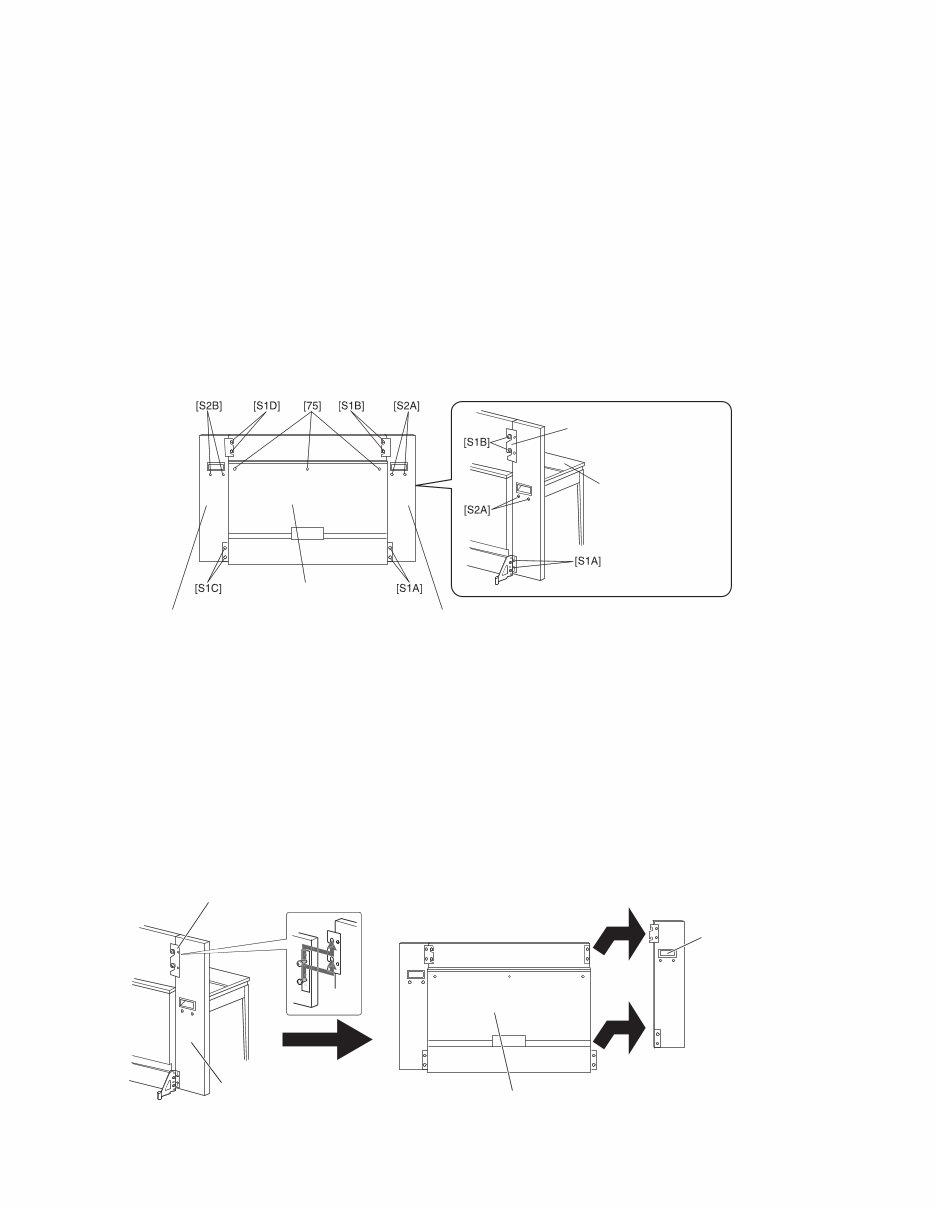
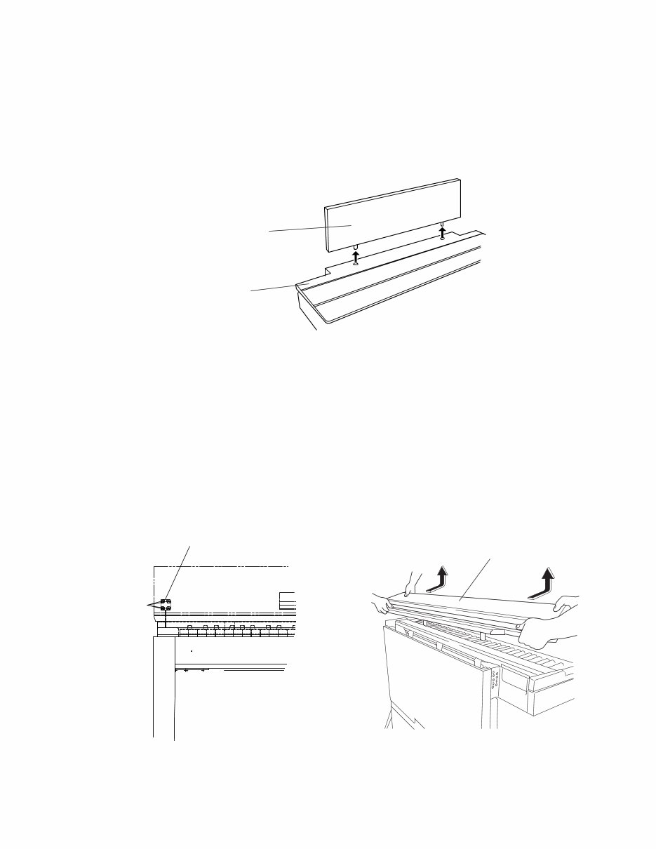
6 F01 ■ DISASSEMBLY PROCEDURE(分解手順) * Take care not to scratch the surface of the finished product during the repair work. * There are many holes on the left and right rear sides of the key bed assembly. When disassembling a circuit board and so on, be careful not to drop the removed screw from the hole. (Fig.6) * 製品にキズを付けないように十分注意して作業して 下さい。 * 棚板の左右後方には穴が沢山あります。基板等を外 す時には、外したネジを穴から落さない様に気をつ けて下さい。(図6) 1. Front Board Assembly L, R, C (Time required: About 2 minutes) * Before disassembling the front board assemblies L, R and C, shut up the key cover assembly completely to protect the key cover assembly from being scratched. 1-1 Remove the two (2) screws marked [S1A] ([S1C]) and the two (2) screws marked [S2A] ([S2B]). (Fig.1) 1. 前板Ass'y L、R、C(所要時間: 約2分) * 蓋Ass'yに傷がつくのを防ぐ為、前板Ass'y L、R、C を外す前に蓋Ass'yを完全に閉めておきます。 [S A] ([S C]) ネジ 、 [S A] ([S B]) ネジ を しま す。( ) Rear Board Assembly (裏板 Ass'y)� Front Board Assembly R (前板 Ass'y R)� Front Board Assembly L (前板 Ass'y L)� Front Plate A (前板プレートA)� Key Cover Assembly (蓋 Ass'y)� [75]: Truss Head Screw 4.0X16 MFZN2B3 (WE977600) 小ネジ+TRUS [S1]: Bind Head Screw 6.0X14 MFZN2B3 (WE987700) 小ネジ+BIND [S2]: Truss Head Screw 6.0X45 MFZN2B3 ( -- ) 小ネジ+TRUS 1-2 Loosen the two (2) screws marked [S1B] ([S1D]) a little. * These two screws are only loosened, not removed. (Fig.1) 1-3 Hold the handle and the edge part of the front board assembly L (R) by both hands, and lift it a little to remove the front plate A from the two loosened screws. Then, remove the front board assembly L (R) horizon- tally to remove it. (Fig.2) [S B] ([S D]) ネジ を しゆるめます。 * このネジ2本はゆるめるだけで外しません。(図1) Assy L( Ass y R) 蓋 を ち、 し ち げて プレートA ネジ引掛 ヶ を し、 Assy L(R)を に移 して します。( ) Front Plate A(前板プレートA)� Front Board Assembly R(前板Ass'y R)� � Rear Board Assembly(裏板Ass'y)� � Handle (裏蓋取手)� Fig.1(図 1) Fig.2(図 2)
7 F01 1-4 After removing the front board assembly L and the front board assembly R, lift up and remove the front board assembly C from the instrument. (Fig.3) * The front board assembly L, R or C is a little heavy. Be careful not to drop and damage it, and not to insure yourself. * When the front board assembly C is inserted in the main unit, do not apply pressure to the front board assembly C from the front or rear. Ass y L Ass y R を してから、 Ass y Cを に ち げ します。( ) * 前板Ass'y L、R、Cは重量があります。落として傷つ けない様、又怪我をしない様に十分注意して下さい。 * 前板Ass'y Cが本体に差し込まれた状態で,前後から力 をかけないで下さい。 Front Board Assembly C (前板 Ass'y C)� Main Unit (メインユニット)� Fig.3(図 3) 2. Key Cover Assembly (Time required: About 4 minutes) 2-1 Remove the front board assemblies L, R and C. (See procedure 1.) 2-2 Open the key cover assembly. 2-3 Remove the four (4) screws marked [87], and incline the damper assembly forward. (Fig.4) 2-4 Remove the three (3) screws marked [75]. (Fig.1) 2-5 Slide the key cover assembly forward to remove it from the guide portions located on left and right sides of the main unit. Then lift it up to remove it from the main unit. (Fig.5) 2. 蓋Ass'y(所要時間: 約4分) Assy L、R、Cを します。( ) 蓋Ass yを けます。 [ ] ネジ を しダンパーAss yを に します。 ( ) [ ] ネジ を します。( ) 蓋Ass yを スライドさせ 右 引掛 を し、 に ち げて します。( ) Damper Assembly(ダンパーAss'y)� [87] Key Cover Assembly(蓋Ass'y)� � Fig.4(図 4) Fig.5(図 5) [87]: Flat Head Tapping Screw-1 3.0X10 BK (WD497000) +皿TP1種
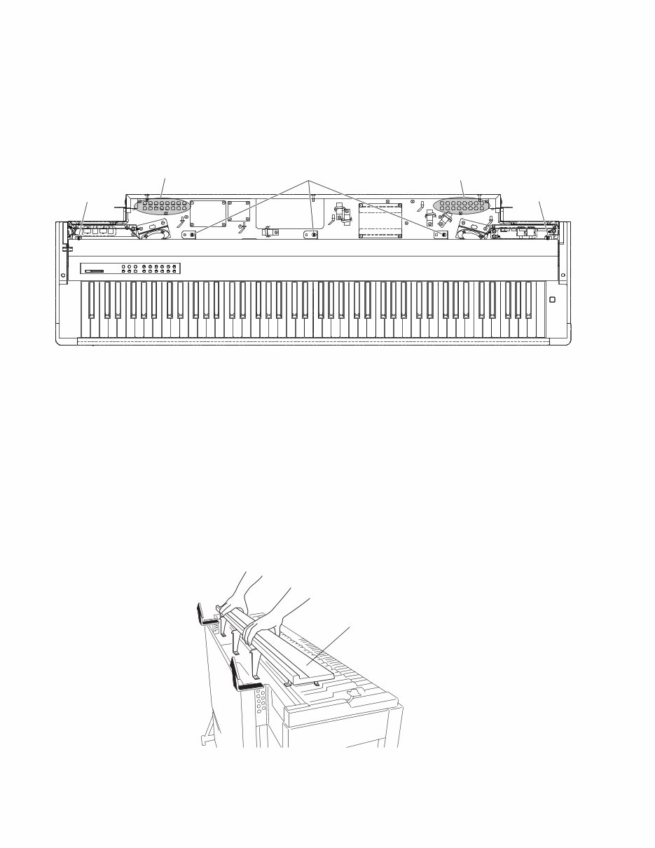
8 F01 3. Panel Assembly (Time required: About 5 minutes) 3-1 Remove the front board assemblies L, R and C. (See procedure 1.) 3-2 Remove the key cover assembly. (See procedure 2.) 3-3 Remove the two (2) screws marked [76]. (Fig.6) 3. パネルAss'y(所要時間: 約5分) Assy L、R、Cを します。( ) 蓋Ass yを します。( ) [ ] ネジ を します。( ) [76] [76] [71] Holes(穴)� Holes(穴)� [71]: Bind Head Tapping Screw-1 3.5X12 MFZN2W3 (WE970900) TP#1+BIND [76]: Bind Head Screw 4.0X10 MFZN2W3 (WE966500) 小ネジ+BIND Fig.6(図 6) 3-4 Remove the three (3) screws marked [71]. (Fig.6) * When reassembling the screw marked [71], if the screw cannot be tightened enough, use the preliminary hole next to the specified hole on the panel holder. (Fig.6) 3-5 Slide the panel assembly backward and remove the wirings from the related three connectors. Then lift it up to remove it from the main unit. (Fig.7) [ ] ネジ を します。( ) * ネジ[71]の再取付け時にネジが効かなくなった場合、 パネル固定金具Aの隣の予備の穴を使用して止めて下 さい。(図6) パネルAss yを ろ スライドさせ、コネクタヶ を き、 あげて 体から します。( ) Panel Assembly(パネルAss'y)� Fig.7(図 7)
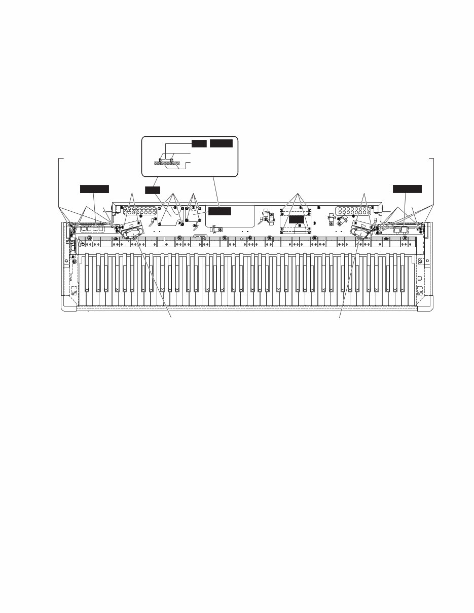
9 F01 4. DM Circuit Board (Time required: About 6 minutes) 4-1 Remove the front board assemblies L, R and C. (See procedure 1.) 4-2 Remove the key cover assembly. (See procedure 2.) 4-3 Remove the panel assembly. (See procedure 3.) 4-4 Remove the four (4) screws marked [78]. The DM circuit board can then be removed. (Fig.8) 4. DMシート(所要時間: 約6分) Assy L、R、Cを します。( ) 蓋Ass yを します。( ) パネルAss yを します。( ) [ ] ネジ を し、DMシートを します。( ) DM [71C] [80A] [64A] [80B] [64B] [78] [71C] [71D] EQ DJACK GND Terminal (アース端子)� Speaker Assembly L (SP Ass'y L)� Speaker Assembly R (SP Ass'y R)� [71A] AJACK A-Jack Assembly (AジャックAss'y)� GND Terminal (アース端子)� D-Jack Assembly (DジャックAss'y)� NET1 [80A] [64A] [80B] [64B] EQ NET1 [71B] [71E] [64]: Spacer (CB040950) スペーサ [71]: Bind Head Tapping Screw-1 3.5X12 MFZN2W3 (WE970900) TP#1+BIND [78]: Bind Head Tapping Screw-B 3.0X8 MFZN2W3 (WE774300) Bタイト+BIND [80]: Bind Head Tapping Screw-1 3.5X20 MFZN2W3 (WE971500) TP#1+BIND Fig.8(図 8) 5. EQ Circuit Board (Time required: About 6 minutes) 5-1 Remove the front board assemblies L, R and C. (See procedure 1.) 5-2 Remove the key cover assembly. (See procedure 2.) 5-3 Remove the panel assembly. (See procedure 3.) 5-4 Remove the four (4) screws marked [80A] and the four (4) spacers marked [64A]. The EQ circuit board can then be removed. (Fig.8) 6. NET1 Circuit Board (Time required: About 6 minutes) 6-1 Remove the front board assemblies L, R and C. (See procedure 1.) 6-2 Remove the key cover assembly. (See procedure 2.) 6-3 Remove the panel assembly. (See procedure 3.) 6-4 Remove the four (4) screws marked [80B] and the four (4) spacers marked [64B]. The NET1 circuit board can then be removed. (Fig.8) 5. EQシート(所要時間: 約6分) Assy L、R、Cを します。( ) 蓋Ass yを します。( ) パネルAss yを します。( ) [ A] ネジ [ A] スペーサ を し、EQシートを します。( ) 6. NET1シート(所要時間: 約6分) Assy L、R、Cを します。( ) 蓋Ass yを します。( ) パネルAss yを します。( ) [ B] ネジ [ B] スペーサ を し、NETシート を します。( )
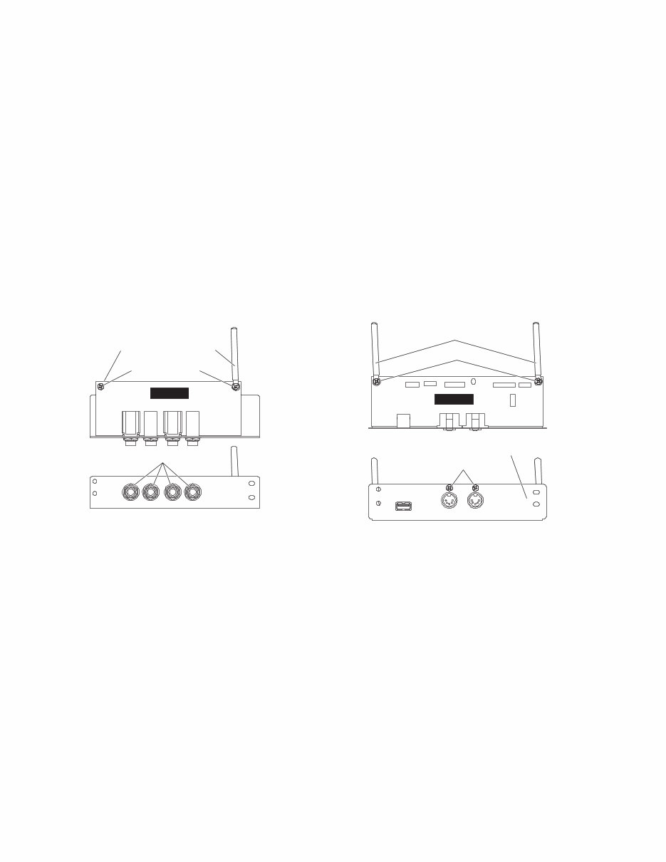
10 F01 7. A-Jack Assembly, AJACK Circuit Board (Time required: About 7 minutes) 7-1 Remove the front board assemblies L, R and C. (See procedure 1.) 7-2 Remove the key cover assembly. (See procedure 2.) 7-3 Remove the panel assembly. (See procedure 3.) 7-4 Remove the three (3) screws marked [71A] and the screw marked [71B]. The A-Jack assembly can then be removed. (Fig.8) * As for the three (3) screws marked [71A], each screw is tightened together with a GND terminal. 7-5 Remove the screw marked [5A] and the screw marked [5B]. (Fig.9) * As for the screw marked [5B], it is tightened together with a cord binder. 7-6 Remove the four (4) hexagonal nuts marked [4] and the four (4) washers marked [3]. The AJACK circuit board can then be removed from the A-Jack assembly. (Fig.9) 7. AジャックAss'y、AJACKシート(所要時間: 約7分) Assy L、R、Cを します。( ) 蓋Ass yを します。( ) パネルAss yを します。( ) [ A] ネジ [ B] ネジ を し、AジャックAssyを します。( ) * [71A]のネジ3ヶ所は、アース端子と共締めされてい ます。 [ A] ネジ [ B] ネジ を します。( ) * [5B]のネジ1ヶ所は、束線止めと共締めされています。 [] ジャックナット [] ワッシャ を し、Aジャック Ass yからAJACKシートを します。( ) AJACK [3] [4] [5A] Cord Binder (束線止め)� A-Jack Assembly (AジャックAss'y)� [5B] [3]: Washer BLACK (VJ869400) ワッシャー [4]: Special Nut M12X14X2 P=1.0 (WF559900) ナット特殊 [5]: Bind Head Tapping Screw-B 3.0X8 MFZN2W3 (WE774300) Bタイト+BIND [3]: Bind Head Tapping Screw-B 3.0X8 MFZN2W3 (WE774300) Bタイト+BIND Fig.9(図 9) Fig.10(図 10) 8. D-Jack Assembly, DJACK Circuit Board (Time required: About 7 minutes) 8-1 Remove the front board assemblies L, R and C. (See procedure 1.) 8-2 Remove the key cover assembly. (See procedure 2.) 8-3 Remove the panel assembly. (See procedure 3.) 8-4 Remove the three (3) screws marked [71D] and the screw marked [71E]. The D-Jack assembly can then be removed. (Fig.8) * As for the three (3) screws marked [71D], each screw is tightened together with a GND terminal. 8-5 Remove the two (2) screws marked [3A] and the two (2) screws marked [3B]. The DJACK circuit board can then be removed from the D-Jack assembly. (Fig.10) * As for the two (2) screws marked [3A], each screw is tightened together with a cord binder. (Fig.10) 8. DジャックAss'y、DJACKシート(所要時間: 約7分) Assy L、R、Cを します。( ) 蓋Ass yを します。( ) パネルAss yを します。( ) [ D] ネジ [ E] ネジ を し、DジャックAssyを します。( ) * [71D]のネジ3ヶ所は、アース端子と共締めされてい ます。 [ A] ネジ [ B] ネジ を し、DジャックAss yから DJACKシートを します。( ) * [3A]のネジ2ヶ所は、それぞれ束線止めと共締めされ ています。 DJACK [3B] [3A] Cord Binder (束線止め)� D-Jack Assembly (DジャックAss'y)�
Are you facing issues with your Yamaha Modus F01 Piano? Why spend a lot on repairs when you can easily do it yourself? This comprehensive service and repair manual is utilized by the Official Certified Yamaha Technicians and will assist you in troubleshooting and fixing your piano.
Contents:
Specifications
Panel Layout
Disassembly Procedure
Lsi Pin Description
Ic Block Diagram
Circuit Boards
Test Program
Data Backup
Version Upgrade
System Booting Flow Chart
Midi Implementation Chart
Midi Data Format
Parts List
Block Diagram
Circuit Board Layout
Overall Circuit Diagram
This manual covers ALL Modus F01 models:
Yamaha Modus F01PO
Yamaha Modus F01PB
Yamaha Modus F01PE
Yamaha Modus F01PR
This service manual is highly detailed with images and step-by-step instructions for the best way to repair/service this device.
Please note that this is the OFFICIAL service and repair manual in PDF format, not a scanned-in or bootlegged copy. The manual is created in high resolution, ensuring excellent print quality for the pages you need.
Gain instant access after payment with no shipping fees or waiting on postal delivery, allowing you to start your repairs right away!
Specifications:
Language: English
Format: PDF
Pages: 128
Platform: Windows and MAC
If you are searching for a service manual and can't find it anywhere, please contact us with your request. With one of the largest service manual databases, there's a good chance we can assist you!
Recently Viewed
5,521,897Happy Clients
2,594,462eManuals
1,120,453Trusted Sellers
15Years in Business
Price:
Actual Price:
Yamaha Modus F01 Series Piano Service Manual & Repair Guide